1
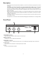
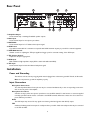
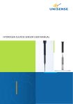
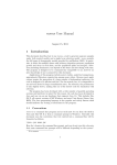
Classic Series Public Address Amplifiers
C10 & C20 Models
Installation and Use Manual
© 2009 Bogen Communications, Inc.
All rights reserved.
Specifications subject to change without notice.
54-5978-01B 0901
Notice
IMPORTANT
Every effort was made to ensure that the information in this
guide was complete and accurate at the time of printing.
However, information is subject to change.
Important Safety Information
CAUTION: TO PREVENT THE RISK OF
ELECTRIC SHOCK, DO NOT REMOVE COVER
(OR BACK). NO USER-SERVICEABLE PARTS
INSIDE. REFER SERVICING TO QUALIFIED
PERSONNEL.
WARNING: To Reduce The Risk of Fire Or Electric Shock,
Do Not Expose This Apparatus To Rain Or Moisture.
Always follow these basic safety precautions when installing and
using the unit:
1.
2.
3.
4.
5.
6.
7.
8.
9.
10.
11.
12.
13.
Read these instructions.
Keep these instructions.
Heed all warnings.
Follow all instructions.
Do not use this apparatus near water.
Clean only with dry cloth.
DO NOT block any ventilation openings. Install in accordance with the manufacturer’s instructions.
Do not install near any heat sources such as radiators, heat
registers, stoves, or other apparatus (including amplifiers)
that produce heat.
Do not defeat the safety purpose of the polarized or
grounding-type plug. A polarized plug has two blades with
one wider than the other. A grounding-type plug has two
blades and a third grounding prong. The wide blade, or the
third prong, are provided for your safety. If the provided
plug does not fit into your outlet, consult an electrician for
replacement of the obsolete outlet.
Protect the power cord from being walked on or pinched,
particularly at plugs, convenience receptacles, and the point
where they exit from the apparatus.
Only use attachments/accessories specified by the manufacturer.
Unplug this apparatus during lightning storms or when
unused for long periods of time.
Refer all servicing to qualified service personnel. Servicing is
required when the apparatus has been damaged in any way,
such as power supply cord or plug is damaged, liquid has
been spilled or objects have fallen into the apparatus, the
apparatus has been exposed to rain or moisture, does not
operate normally, or has been dropped.
The lightning flash with arrowhead symbol, within an equilateral triangle, is
intended to alert the user to the presence of uninsulated “dangerous voltage” within the product’s enclosure
that may be of sufficient magnitude to
constitute a risk of electric shock to
persons.
The exclamation point within an equilateral triangle is intended to alert the
user to the presence of important
operating and maintenance (servicing)
instructions in the literature accompanying the appliance.
2
Contents
DESCRIPTION ....................................................................................................................4
FRONT PANEL....................................................................................................................4
REAR PANEL ......................................................................................................................5
INSTALLATION..................................................................................................................5
Power and Grounding ........................................................................................................................5
Input Connections ..............................................................................................................................5
Microphone Connections ..............................................................................................................5
Microphone Precedence ................................................................................................................5
AUX ................................................................................................................................................5
TEL ..................................................................................................................................................5
Output Connections ..........................................................................................................................6
Speakers, General ..........................................................................................................................6
OPERATION ........................................................................................................................6
POWER ..........................................................................................................................................6
MIC1, MIC2 ..................................................................................................................................6
AUX ................................................................................................................................................6
TEL ..................................................................................................................................................6
VOX SENS ......................................................................................................................................6
Microphone Precedence ................................................................................................................6
TREBLE............................................................................................................................................6
Overload Protection........................................................................................................................6
ACCESSORIES ....................................................................................................................7
TECHNICAL SPECIFICATIONS ......................................................................................7
LIMITED WARRANTY ....................................................................................Back Cover
3
Description
Bogen Models C10 and C20 public address amplifiers are rated at 10 and 20 watts, respectively, and are UL and
C-UL listed.
The amplifiers accommodate low-impedance microphones and high-impedance auxiliary sources. A front panel
selector switch offers a choice of either two low-impedance balanced microphones (MIC1, MIC2), or one microphone and one auxiliary input (MIC1, AUX). The AUX input can be muted when a customer-supplied SPST normally open switch is used for microphone precedence. Independent volume controls and a treble control, for tonal
balance, are provided.
Balanced and unbalanced outputs are provided for 4-, 8-, and 16-ohm speakers and for 25- and 70-volt constant
voltage systems. An accessory transformer, Bogen Model WMT1A, can be installed to provide input- and outputmatching to a telephone line.
The amplifiers operate from a 120V AC, 60 Hz source. A thermostat enclosed in the power transformer protects
the unit against overloads.
The amplifier also accommodates a transformer-balanced TEL/page input with VOX detector for muting the AUX.
Front Panel
1. MIC2/AUX Mode Switch
Switch selects either the MIC2 or AUX connection as the active input.
2. MIC1 Level Control
Individual level control for dedicated microphone input.
3. MIC2/AUX Level Control
Individual level control for a dedicated microphone input or for an auxiliary input depending on input mode selected.
4. Treble Control
Controls the amount of attenuation to treble frequencies above 10 kHz.
5. Power
AC Power switch. Illuminates when ON.
4
Rear Panel
1. Amplifier Output
Screw terminal strip containing all available speaker outputs.
2. Mute Input
Screw terminal input for microphone precedence.
3. MIC1/MIC2
Screw terminal input for Lo-Z balanced microphone signal.
4. AUX Power
A grounded, unswitched AC convenience receptacle with 300W maximum capacity is provided for external equipment.
5. VOX SENS Control
Variable control for adjusting the TEL input signal level trigger point for automatic muting of the AUX input.
6. TEL Volume Control
Adjusts the telephone paging level.
7. AUX Input
RCA unbalanced, high-impedance input (AUX is switch-selectable with MIC2).
8. TEL Input
Screw terminal input for 600-ohm balanced telephone signal.
Installation
Power and Grounding
The AC line cord has a three-prong plug which must be plugged into a three-wire grounded 120-volt, 60 Hz outlet.
Note: It is important to ground the amplifier properly.
Input Connections
Microphone Connections
Two low-impedance balanced microphones may be connected simultaneously to the corresponding screw terminals on the rear panel of the amplifier.
Microphone Precedence
A built-in circuit provides microphones’ precedence over the AUX channel. For this function, a customer-supplied
normally-open SPST switch must be connected to the MUTE terminals. When the contacts are closed, the microphone will have precedence.
AUX
The AUX inputs may be used for any signal source having a line-level (greater than 85mV) output.
TEL
A balanced isolating transformer input for a telephone line is provided. A 600-ohm telephone line may be connected
to the TEL terminals.
5
Output Connections
Speakers, General
The amplifier may be used with most conventional speaker systems. Connect one speaker lead to the screw terminal that corresponds to the total impedance or proper voltage of the speakers used in the system and the other
lead to the COM terminal. For balanced output lines, remove the link between the COM and GND output terminals. Class 2 wiring may be used.
Operation
POWER
The front panel ON/OFF switch applies power to the amplifier.
MIC1, MIC2
For two microphone inputs, the MIC2/AUX selector switch should be in the MIC2 mode. The MIC controls are
used to adjust the volume of the microphone inputs. Rotate the controls clockwise to increase volume and counterclockwise to decrease it. Turn the controls to the minimum counter-clockwise position if the inputs are not
used.
AUX
For one auxiliary input, the MIC2/AUX selector switch should be in the AUX position. The AUX control is used
to adjust the volume of the auxiliary input. Rotate the control clockwise to increase volume and counterclockwise
to decrease it. Turn the control to the minimum counter-clockwise position if the input is not used.
TEL
The TEL volume control on the rear panel adjusts the telephone paging level. It does not affect the microphone
level. Rotate the control counterclockwise to decrease the level. Rotate the control clockwise to increase the level.
Turn the control to the minimum counter-clockwise position if the input is not used.
VOX SENS
The VOX SENSitivity control should be set so that only the desired TEL signal is above the threshold level, while
noise and unwanted signal is below it. When an input signal (such as a voice) is detected, the AUX channel will be
muted. To adjust the sensitivity of the circuit:
1. Rotate the control fully clockwise. While making a page announcement and talking at a low level, the sound
should not be choppy nor missing parts of words. If it is choppy, or if intelligibility is poor, rotate the control counter-clockwise to the point where the sound is clear and crisp (but not to the maximum counterclockwise position).
2. If the background music shuts down when no page is in progress, rotate the control clockwise until the
music is restored.
Microphone Precedence
Muting the AUX channel can be accomplished with a customer-supplied normally-opened SPST switch, which must
be connected to the MUTE terminals. When the contacts are closed, the microphone will have precedence over
the AUX input.
TREBLE
Use the TREBLE control to adjust the tonal balance of the amplifier output. Rotated fully clockwise there is no
effect. Rotate counterclockwise to attenuate the TREBLE of the audio.
Overload Protection
The amplifier output is protected against overload and shorted speaker lines by an electronic shut down circuit and
a thermostat enclosed in the power transformer. If the protection operates, the amplifier will have no output. Set
the Power switch to off and wait a reasonable amount of time for the protection to reset. If the protection trips
again, have the problem investigated by a qualified technician.
6
Accessories
WMT1A - Line-Matching Transformer
• Hi-Z, 10k-ohm primary impedance
• Lo-Z, 600-ohm secondary impedance, balanced with center tap
• Matches high-impedance unbalanced or low-impedance balanced signals
• Jumper selection allows line level signal to microphone level signal conversion
RPK35B - Rack Panel Kit
• RPK35B adapts Classic Series amps (Models C10, and C20) for 19" rack mounting, 2 rack spaces (3-1/2")
• Heavy gauge steel construction
WMK1 - In-Wall Mounting Kit
• Cabinet fits between standard 2 x 4’s on standard 16"
• Controls are accessible via a tilt-open door
• Heavy gauge steel construction
Technical Specifications
Power Output (RMS)
C10:
C20:
Distortion
Frequency Response
Hum and Noise
MIC Input:
AUX Input:
TEL Input:
Input Sensitivity
MIC Lo-Z Balanced:
AUX:
TEL:
Outputs
Output Connections:
Input Connections:
MIC/TEL:
AUX:
Controls:
Tone Control:
Power Requirements:
C10:
C20:
Dimensions:
Product Weight
C10:
C20:
10W
20W
Less than 1% @ Rated Power Output
70 Hz - 16 kHz (±1 dB)
(20 Hz to 20 kHz)
55 dB below rated output
70 dB below rated output
70 dB below rated output
600 µV
85 mV
75 mV
4, 8, 16 ohms, 25V, and 70V
Screw terminal strip
Lo-Z screw terminals
RCA jack
MIC1, MIC2/AUX (switch selected), TREBLE, VOX, TEL
TREBLE: -10 dB to 0 dB @ 10 kHz
120V AC, 60 Hz
38W
50W
11-3/8" W x 2-7/8" H x 7-3/8" D (both models)
5 lb.
6 lb.
7
Limited Warranty; Exclusion of Certain Damages
Bogen Classic Series Amplifiers (Models C10 and C20) are warranted to be free from defects in material or workmanship for two
(2) years from the date of sale to the original purchaser. Any part of the product covered by this warranty that, with normal installation and use, becomes defective will be repaired or replaced by Bogen, at our option, provided the product is shipped insured and
prepaid to: Bogen Factory Service Department, 50 Spring Street, Ramsey, NJ 07446, USA. The product will be returned to you
freight prepaid. This warranty does not extend to any of our products that have been subjected to abuse, misuse, improper storage, neglect, accident, improper installation or have been modified or repaired or altered in any manner whatsoever, or where the
serial number or date code has been removed or defaced.
THE FOREGOING LIMITED WARRANTY IS BOGEN’S SOLE AND EXCLUSIVE WARRANTY AND THE PURCHASER’S SOLE AND EXCLUSIVE REMEDY. BOGEN MAKES NO OTHER WARRANTIES OF ANY KIND,
EITHER EXPRESS OR IMPLIED, AND ALL IMPLIED WARRANTIES OF MERCHANTABILITY OR FITNESS FOR
A PARTICULAR PURPOSE ARE HEREBY DISCLAIMED AND EXCLUDED TO THE MAXIMUM EXTENT
ALLOWABLE BY LAW. Bogen's liability arising out of the manufacture, sale or supplying of products or their use or disposition, whether based upon warranty, contract, tort or otherwise, shall be limited to the price of the product. IN NO EVENT
SHALL BOGEN BE LIABLE FOR SPECIAL, INCIDENTAL OR CONSEQUENTIAL DAMAGES (INCLUDING,
BUT NOT LIMITED TO, LOSS OF PROFITS, LOSS OF DATA OR LOSS OF USE DAMAGES) ARISING OUT OF
THE MANUFACTURE, SALE OR SUPPLYING OF PRODUCTS, EVEN IF BOGEN HAS BEEN ADVISED OF THE
POSSIBILITY OF SUCH DAMAGES OR LOSSES. Some States do not allow the exclusion or limitation of incidental or consequential damages, so the above limitation or exclusion may not apply to you. This warranty gives you specific legal rights, and you
may also have other rights which vary from State to State.
Products that are out of warranty will also be repaired by the Bogen Factory Service Department -- same address as above or call
201-934-8500. The parts and labor involved in these repairs are warranted for 90 days when repaired by the Bogen Factory Service
Department. All shipping charges in addition to parts and labor charges will be at the owner's expense. All returns require a Return
Authorization number.
07/22/2008
50 Spring Street, Ramsey, NJ 07446, U.S.A.
Tel. 201-934-8500, Fax: 201-934-9832, www.bogen.com