1
to 10 V for a load current of 0 to 2 A. (In the earlier versions a different current
monitoring voltage is produced when changing from I a>b to I b>a. It is linear and
repeatable in each current direction but it is different. The exact calibration information
will be supplied with the product.
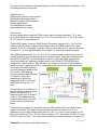
Internally the series regulating element (a FET) is fan cooled, as it can dissipate up to
20 V at 2 A = 40 W. If the fan should fail or the power dissipation be exceeded and the
temperature rises above a preset level then the unit will switch off automatically until
the temperature decreases when it will switch back on again. This temperature
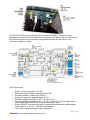
threshold is adjusted using VR8 (beneath the right hand side cover), it is initially set to
approximately 70 deg C.
An output voltage monitoring circuit indicates when the output voltage goes above
about 20 V – typically when the load is disconnected or the output voltage compliance
is exceeded (more than about 10 ohms). An LED indicates when this occurs and VR3
sets the output voltage at which the LED illuminates (beneath the left hand side cover).
ConnectionDetails
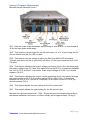
PWM IN+, PWM IN- - Pulse width modulator input, 0-5 V or 0-24 V (depends on
internal configuration).
0V, Sin (4-20mA) - Process signal input, typically 0-20 mA or 4-20 mA.
0V, 0-5 Vin - Direct voltage control input.
+Vin, 0Vin - Power supply input, 24 VDC.
The POLARITY REVERSE control input reverses the polarity of the output current, 0-5
V (J5 in) or 0-24 V (J5 out) (depends on internal configuration). When off the
conventional current flow is from A to B, when switched on the conventional current
flow is from B to A.
The OUTPUT ON/OFF control input switches the output on, 0-5 V (J6 in) or 0-24 V (J6
out) (depends on internal configuration).
Iout(0-10V) - Load current monitoring output 0 to 10 V = 0-2 A (not isolated)
Vout(0-10V) - Load voltage monitoring output 0 to 10 V = 0-20 V (not isolated)
OUT A, OUT B - Output connections to the load (OUT A nominally +ve)
3|Page
danntech – PROCESS INSTRUMENTATION 2015
©