1
One Jake Brown Road
Old Bridge, NJ 08857-1000 USA
(800) 523-6049 • (732) 679-4000 • FAX: (732) 679-4353
www.blondertongue.com
INSTRUCTION MANUAL
HDE-4S-QAM
MPEG-2 HD Encoder
Model
Stock No.
HDE-4S-QAM
6374A
Description
MPEG-2 HD Encoder
4xHD-SDI+ 4xComponent/Composite inputs;
4xQAM + 4xGigE + 4xASI outputs; EAS compatible
Status
Date
Document No.
Issue No.
Author
Active
August 13, 2013
651229100C
3
KK
Obsolete
May 28, 2013
651229100B
2
KK
Obsolete
March 8, 2013
651229100A
1
KK
©2013 Blonder Tongue Laboratories, Inc. All rights reserved. Specifications are subject to change without notice. Trademarks are the property of their respective owner.
2 HDE-4S-QAM
Instruction Manual
We recommend that you write the following information in the spaces provided below.
Purchase Location Name:
Purchase Location Telephone Number:
HDE-4S-QAM Serial Number:
The information contained herein is subject to change without notice. Revisions may be
issued to advise of such changes and/or additions.
Correspondence regarding this publication should be addressed directly to:
Blonder Tongue Laboratories, Inc.
One Jake Brown Road
Old Bridge, NJ 08857 USA
Document Number: 651229100C
Printed in the United States of America.
All product names, trade names, or corporate names mentioned in this document are
acknowledged to be the proprietary property of the registered owners.
This product incorporates copyright protection technology that is protected by U.S. patents and other
intellectual property rights. Reverse engineering or disassembly is prohibited.
HDE-4S-QAM 3
Instruction Manual
Table of Contents
SECTION 1 – GENERAL & SAFETY INSTRUCTIONS ...................................................................................................... 4
SECTION 2 – PRODUCT SUMMARY.............................................................................................................................. 6
2.1 REVISION HISTORY & REASON.................................................................................................................................... 6
2.2 PRODUCT APPLICATION & Description................................................................................................................... 6
2.3 PRODUCT SPECIFICATION........................................................................................................................................... 9
SECTION 3 – INSTALLATION & POwER-UP ................................................................................................................. 10
3.1 UNPACKINg ............................................................................................................................................................... 10
3.2 INSTALLATION ........................................................................................................................................................... 10
3.3 POWER-UP................................................................................................................................................................. 10
SECTION 4 – Communicating with the unit....................................................................................................... 11
SECTION 5 – CONFIGURING THE UNIT ....................................................................................................................... 12
5.1 ACCESSINg THE UNIT VIA THE WEB Browser ....................................................................................................... 12
5.2 "Main > STATUS" SCREEN ........................................................................................................................................ 13
5.3 "Main > Program" SCREEN................................................................................................................................... 14
5.4 "Main > video" Screen.......................................................................................................................................... 15
5.5 "Main > Audio" Screen......................................................................................................................................... 16
5.6 "main > TS Map" Screen....................................................................................................................................... 18
5.7 "Main > TS Config" Screen................................................................................................................................... 20
5.8 "Main > IP" Screen................................................................................................................................................. 23
5.9 "Main > QAM" Screen............................................................................................................................................ 24
5.10 "Main > Output" screen.................................................................................................................................... 26
5.11 "Main > Refresh" Tab.......................................................................................................................................... 27
5.12 "network" Screen.............................................................................................................................................. 28
5.12.1 "Admin.html" HIDDEN SCREEN.............................................................................................................. 30
5.13 "TIME" SCREEN....................................................................................................................................................... 33
5.14 "Event LOG" SCREEN............................................................................................................................................. 34
appendix A – UPDATING THE SOFTWARE Remotely.............................................................................................. 35
Appendix B – Viewing the ip output on a vlc media player........................................................................ 38
4 HDE-4S-QAM
Instruction Manual
Section 1 — General & Safety Instructions
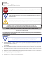
The STOP sign symbol is intended to alert you to the presence of REQUIRED operating and maintenance
(servicing) instructions that if not followed, may result in product failure or destruction.
The YIELD sign symbol is intended to alert you to the presence of RECOMMENDED operating and maintenance
(servicing) instructions.
The LIGHTNING flash symbol is intended to alert you to the presence of uninsulated "dangerous voltage"
within the product's enclosure that may be of sufficient magnitude to constitute a risk of electrical shock.
TO REDUCE THE RISK OF ELECTRICAL SHOCK, DO NOT REMOVE COVER FROM THIS UNIT. NO USER-SERVICEABLE PARTS INSIDE. REFER SERVICING TO QUALIFIED SERVICE PERSONNEL.
WARNING: TO PREVENT FIRE OR SHOCK HAZARD, DO NOT EXPOSE THIS UNIT TO RAIN OR MOISTURE
NOTE TO CATV SYSTEM INSTALLER
This reminder is provided to call the CATV System Installer’s attention to Article 820-40 of the NEC that provides guidelines for
proper grounding and, in particular, specifies that the cable ground shall be connected to the grounding system of the building, as
close to the point of cable entry as practical.
Safety Instructions
You should always follow these instructions to help ensure
Against injury to yourself and damage to your equipment.
➥ E levated Operating Ambient - If installed in a closed or multi-unit rack assembly, the operating ambient temperature of the rack environment
may be greater than room ambient. Therefore, consideration should be given to installing the equipment in an environment compatible with the
maximum ambient temperature per Section 2.3.
➥ R
educed Air Flow - Installation of the equipment in a rack should be such that the amount of air flow required for safe operation of the equipment
is not compromised.
➥ Mechanical Loading - Mounting of the equipment in the rack should be such that a hazardous condition is not achieved due to uneven mechanical loading.
➥ C
ircuit Overloading - Consideration should be given to the connection of the equipment to the supply circuit and the effect that overloading of
the circuits might have on overcurrent protection and supply wiring. Appropriate consideration of equipment nameplate ratings should be used
when addressing this concern.
➥ R
eliable Earthing - Reliable earthing of rack-mounted equipment should be maintained. Particular attention should be given to supply connections
other than direct connections to the branch circuit (e.g. use of power strips).
➥ Read all safety and operating instructions before you operate the unit.
➥ Retain all safety and operating instructions for future reference.
➥ Heed all warnings on the unit and in the safety and operating instructions.
HDE-4S-QAM 5
Instruction Manual
Safety Instructions - continued
➥ Follow all installation, operating, and use instructions.
➥ Unplug the unit from the AC power outlet before cleaning. Use only a damp cloth for cleaning the exterior of the unit.
➥ Do not use accessories or attachments not recommended by Blonder Tongue, as they may cause hazards, and will void the warranty.
➥ Do not operate the unit in high-humidity areas, or expose it to water or moisture.
➥ D
o not place the unit on an unstable cart, stand, tripod, bracket, or table. The unit may fall, causing serious personal injury and damage to the
unit. Install the unit only in a mounting rack designed for 19” rack-mounted equipment.
➥ D
o not block or cover slots and openings in the unit. These are provided for ventilation and protection from overheating. Never place the
unit near or over a radiator or heat register. Do not place the unit in an enclosure such as a cabinet without proper ventilation. Do not mount
equipment in the rack space directly above or below the unit.
➥ Operate the unit using only the type of power source indicated on the marking label. Unplug the unit power cord by gripping the plug, not the cord.
➥ T he unit is equipped with a three-wire ground-type plug. This plug will fit only into a ground-type power outlet. If you are unable to insert the
plug into the outlet, contact an electrician to replace the outlet. Do not defeat the safety purpose of the ground-type plug.
➥ R
oute power supply cords so that they are not likely to be walked on or pinched by items placed upon or against them. Pay particular attention
to cords at plugs, convenience receptacles, and the point where they exit from the unit.
➥ B
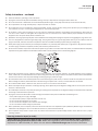
e sure that the outdoor components of the antenna system are grounded in accordance with local, federal, and National Electrical Code (NEC)
requirements. Pay special attention to NEC Sections 810 and 820. See the example shown in the following diagram:
➥ W
e strongly recommend using an outlet that contains surge suppression or ground fault protection. For added protection during a lightning
storm, or when the unit is left unattended and unused for long periods of time, unplug it from the wall outlet and disconnect the lines between
the unit and the antenna. This will prevent damage caused by lightning or power line surges.
➥ D
o not locate the antenna near overhead power lines or other electric light or power circuits, or where it can fall into such power lines or circuits.
When installing the antenna, take extreme care to avoid touching such power lines or circuits, as contact with them can be fatal.
➥ Do not overload wall outlets or extension cords, as this can result in a risk of fire or electrical shock.
➥ N
ever insert objects of any kind into the unit through openings, as the objects may touch dangerous voltage points or short out parts. This could
cause fire or electrical shock.
➥ D
o not attempt to service the unit yourself, as opening or removing covers may expose you to dangerous voltage and will void the warranty. Refer
all servicing to authorized service personnel.
➥ Unplug the unit from the wall outlet and refer servicing to authorized service personnel whenever the following occurs:
❏
❏
❏
❏
❏
The power supply cord or plug is damaged;
Liquid has been spilled, or objects have fallen into the unit;
The unit has been exposed to rain or water;
The unit has been dropped or the chassis has been damaged;
The unit exhibits a distinct change in performance.
➥ W
hen replacement parts are required, ensure that the service technician uses replacement parts specified by Blonder Tongue. Unauthorized
substitutions may damage the unit or cause electrical shock or fire, and will void the warranty.
➥ U
pon completion of any service or repair to the unit, ask the service technician to perform safety checks to ensure that the unit is in proper
operating condition.
Returning Product for Repair (or Credit)
A Return Material Authorization (RMA) Number is required on all products returned to Blonder Tongue, regardless if
the product is being returned for repair or credit. Before returning product, please contact the Blonder Tongue Service
Department at 1-800-523-6049, Ext. 4256 or visit our website: www.blondertongue.com for further information.
6 HDE-4S-QAM
Instruction Manual
Section 2 — Product Summary
2.1 Revision History & Reason
This is the third issue of the Instruction Manual.
The reason for this revision was to reflect the updated web pages and features now available with software version 1.0.17
and above.
The reason for the second revision was to reflect the updated web pages and features now available with software version
1.0.14.
2.2 Product Application & Description
Application:
HDE-4S-QAM (MPEG-2 HD Encoder – 4xHD-SDI/4xComponent/Composite – 4xQAM) accepts up to four (4) high-definition
(HD) programs from any of the following inputs: 4xHD-SDI and 4xComponent/Composite. MPEG-2 encoded outputs are
available in the following formats simultaneously: 4xQAM, 4xGigE (1000Base-T Ethernet), and 4xASI.
To improve transport efficiency, the encoder allows operator to (i) assign one (1) to four (4) programs to each QAM output
channel, and (ii) to individually turn on/off each of the four (4) adjacent QAM output channels.
The encoder supports Dolby® Digital audio encoding, and Closed Captioning (EIA-608 and EIA-708). It is also equipped with
an Emergency Alert System (EAS) interface. A front-panel RF test point allows for monitoring/testing of the QAM output
without service interruption.
Comprehensive remote monitoring and control is accomplished using any standard Web browser via a front-panel
10/100Base-T Ethernet connection.
Features:
• Accepts up to four (4) programs from any of the following inputs: 4xHD-SDI and 4xComponent/Composite
• Simultaneously delivers the following outputs: 4xQAM, 4xGigE, and 4xASI
• Multiplexes up to four (4) input programs in any of the following output combinations:
(i) 1:1 (1 program per QAM channel)
(ii) 2:1 (2 programs per QAM channel, not exceeding 38.8 Mbps)
(iii) 3:1 (3 programs per QAM channel, not exceeding 38.8 Mbps)
(iv) 4:1 (4 programs per QAM channel, not exceding 38.8 Mbps)
• Each of the four (4) QAM channels can (i) contain 1 or 2 programs, and (ii) be turned on/off individually
• Provides +52 dBmV QAM output level for four (4) combined channels (+60 dBmV for 1 QAM)
• Provides comprehensive GUI-based monitoring and control via standard Web browsers
• Supports Closed Captioning EIA-608 and EIA-708
• Equipped with EAS interface (Analog Video + L/R Audio)
• Supports Real-time Dolby® Digital audio encoding
• Supports user-defined PSIP configuration
Real Time Application:
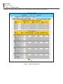
The HDE-4S-QAM is designed to accept up to four (4) high-definition programs as a combination of the following:
i) up to two (2) inputs from any of the following: Component 1, Component 2, Composite 1, Composite 2, HD-SDI 1, or HD-SDI 2
ii) up to two (2) inputs from any of the following: Component 3, Component 4, Composite 3, Composite 4, HD-SDI 3, or HD-SDI 4
Once MPEG-2 encoded, the four (4) output programs can be assigned to either Single Program Transport Streams (SPTS) or
Multi-Program Transport Streams (MPTS). The four (4) output programs can be assigned to the QAM, ASI, and IP outputs
as follows:
No. of SPTS
No. of MPTS
No. QAM RF
Channels used
4
3
2
1
0
0
N/A
N/A
1 (2 progs.)
1 (3 progs.)
2 (2 progs.)
1 (4 progs.)
4
3
3
2
2
1
No. ASI
No. of IP outputs
Connectors used
available
4
3
3
2
2
1
4
3
3
2
2
1
HDE-4S-QAM 7
Instruction Manual
Description:
Front panel connectors and indicators:
1
2
3
[4]
4
[5]
5
[6]
6
[6]
8
7 [6]
[6]
1 DATA OUT 1 GIGE:
RJ45 connector for GigE (1000Base-T Ethernet) interface for multiplexed SPTS or MPTS output streams. Only static IP address can be
assigned to this interface. The factory default value is 192.168.253.1.
2 REMOTE CONTROL 10/100:
RJ45 connector for 10/100Base-T Ethernet interface for monitoring and configuring the unit. Only static IP address can be assigned to
this interface. The factory default value is 172.16.70.1.
3 IP RESET:
When pushed and held for about 10 seconds, resets the IP address, Usernames, and Passwords to Factory default values as follows:
IP address = 172.16.70.1
Username = Admin (case-sensitive)
Password = pass (case-sensitive)
4 AUDIO & VIDEO LEDs:
LEDs indicate the status of video and audio of each of the four inputs as follows:
Audio LED
Green = Audio input type detected is Analog (L/R) or Digital Audio (PCM)
Red = Audio input with error
Off = Audio input not detected
Video LED
Green = Video input type detected is Component (YPbPr) or HD-SDI
Red = Video input with error
Off = Video input not detected
5 ASI OUT:
The “ASI OUT” BNC connectors 1 to 4 delivers multiplexed SPTS or MPTS output and is typically used as input to an external modulator.
6 -20 dB QAM RF TEST:
“F” connector for RF testing -20dB referenced from the main output.
7 ENCODER: LED indicates the status of the two internal encoder chipsets as follows:
LED is Blue = two encoder chipsets are encoding (no input signal needs to be present).
LED is Off = one or both of the of the encoder chipsets are not encoding, or their normal operating temperature has been
exceeded.
8 POWER: LED is Green = AC power is detected.
LED is off = indicates (i) AC power is not connected, or (ii) AC power is connected but the power supply is defective. The unit must be sent
to Blonder Tongue for repair for condition (ii).
8 HDE-4S-QAM
Instruction Manual
Rear panel connectors:
10
12
13
14
15
13
14
9
11
16
9 INPUT POWER:
IEC 14 power inlet plug - rated 115/230 VAC; 2.0/1.0A; 60/50 Hz; equipped with Slo-Blo, 3.0 Amps, 250 V Fuse.
10 EAS CONTROL:
Terminal strip to activate the EAS messaging feature in one of two following ways:
a) 5-12 VDC between terminals 1 & 3 shown below
b) Dry Contact between terminals 2 & 3 shown below
1 2 3
GND
NOTE: This feature is intended to activate EAS and override all input programs (whether HD-SDI or Component)
with the EAS INPUT (see 11 below for details). The QAM RF OUT (see 12 below), ASI OUT (see 5 ) and DATA OUT
(see 1 ) will all contain the EAS content on every program.
11 EAS INPUT: RCA connectors for EAS Analog Audio (marked L & R) and Composite Video (marked VIDEO) inputs.
EAS feature is functional only when (i) EAS Control is triggered ON, and (ii) Video/audio is detected on EAS INPUT connectors. The EAS feature will not be functional unless both
these conditions are met.
12 QAM RF OUTPUT:
“F” connector for up to four (4) QAM RF outputs.
13 AUDIO IN 1, 2, 3 & 4:
RCA connectors (marked L and R) for Analog Left/Right Audio inputs and RCA connectors (marked “DIGITAL”) for
Digital Audio program inputs.
14 COMPONENT IN 1, 2, 3 & 4:
RCA connectors (marked Pr, Pb, Y) for Analog Component Video inputs. The RCA connectors (marked Y) are also
used for Composite Video input.
15 CC IN 1, 2, 3 & 4:
RCA connectors (marked “CC IN”) for Analog NTSC Closed Captioning (EIA-608, also known as Line 21), which will
then be digitized and inserted in the MPEG-2 Transport Stream of the Component inputs.
16 HD-SDI 1 - 4:
BNC connectors to receive the HD-SDI input.
HDE-4S-QAM 9
Instruction Manual
2.3 Product Specification
Input
Output
HD-SDI
Connectors:
Standard:
Video Resolution:
Audio:
Component
Connectors:
Video Resolution:
Video Aspect Ratio:
Audio:
4x BNC
SMPTE 292M
480i, 720p, & 1080i
Embedded PCM and pass-through Dolby® Digital only
4 sets each 3x RCA for Video (Y, Pb, Pr)
480i, 720p, & 1080i
4:3 & 16:9
4 sets each 2x RCA for Analog Audio (L, R)
4 sets each 1x RCA for Digital Audio (PCM)
Composite
Connectors: 4 sets each 1x RCA for Video (Y)
Video Resolution: 480i
Audio: 4 sets each 2x RCA for Analog Audio (L, R)
4 sets each 1x RCA for Digital Audio (PCM)
EAS (Emergency Alert System)
Connectors: 3x RCA (Video, Audio L & R)
Trigger Mechanism: 5-12 VDC & Dry Contact Closure (Terminal Strip)
Encoding Profile
Video
Audio
Output Format:
Chroma:
Resolution:
Frame rate:
Aspect Ratio:
GOP Structure:
Transport Rate:
Video Rate:
Video Pre-filter:
Color Space:
MPEG-2 HD MP@ML; ISO 13818-2
4:2:0
480i, 720p, & 1080i
29.97 fps (480i); 29.97 fps (1080i); 59.97 fps (720p)
4:3 & 16:9
I & P frames (user-selectable)
Variable (user-selectable)
Variable (user-selectable)
Variable (user-selectable)
YCbCr and RGB
Output Format: Dolby® Digital
Sampling rate: 48 kHz
Bit rate: Variable; 96-448 Kbps (user-selectable)
Closed Captioning
HD-SDI: EIA-708; Embedded in HD-SDI input
Component: EIA-608
Composite: EIA-608
General
QAM
Connector:
Modulation:
Standards:
DVB Symbol Rate:
Frequency Range:
Tuning:
Channels’ Bandwidth:
RF Level:
RF Level Accuracy:
Frequency Tolerance:
Frequency Stability:
Amplitude Flatness:
Phase Noise:
Spurious:
Broadband Noise:
Impedance:
Spectral Inversion:
Carrier Suppression:
Return Loss:
Signal-to-Noise Ratio (SNR):
MER:
I/Q Phase Error:
I/Q Amplitude Imbalance:
ASI
1x “F” Female (rear panel; up to 4x RF QAM ch. combined)
QAM 16, 32, 64, 128, and 256
ITU-T J.83; Annex A and B
Variable; up to 7 MSymbol/sec (MBaud)
54 to 1002 MHz
CATV Channel Selectable (Ch. 2 to 158)
24 MHz (4x Adjacent 6 MHz)
+42 to +52 dBmV, 1 dB increment (4 ch. combined)
+46 to +56 dBmV, 1 dB increment (2 ch. combined)
± 1 dB
± 0.5 kHz @ 77 °F (25 °C)
± 5 kHz over 32 to 122 °F (0 to 50 °C)
± 0.25 dB (over 6 MHz channel)
-98 dBc (@ 10 kHz)
-57 dBc
-70 dBc (@ +52 dBmV output level, 5.5 MHz bandwidth)
75 Ω
Auto Recognition
45 dB
14 dB typical
40 dB typical
40 dB typical
Less than 1 degree
Less than 1%
Connectors: 4x BNC (Front-panel)
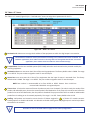
Output Assignment: 4 output programs can be assigned as follows:
No. of SPTS
4
3
2
0
0
No. of MPTS
N/A
N/A
1 (2 progs.)
2 (2 progs.)
1 (4 progs.)
Connectors used
(user-defined)
1,2,3,4
1,2,3
1,2,3
1,2
1
Format: DVB-ASI
Standard: ETSI EN 50083-9
GigE
Connector:
Standard:
UDP/RTP:
Address Assignment:
1x RJ45 (Front-panel)
1000Base-T Ethernet
Supported (user-selectable)
4x IPv4 addresses & port numbers (user-selectable)
Alarms/Monitoring/Control
Dimensions (W x D x H):
19.0 x 18.125 x 1.75 inches (483 x 460 x 44 mm)
Power:
115-230VAC, 60/50Hz (Fuse:3.0A, 250VDC, Slo Blo)
Power Dissipation:
60 W
Weight:
8 lbs (3.6 kg)
Operating Temperature:
32 to 122 °F (0 to 50 °C)
Storage Temperature:
-13 to 158 °F (-25 to 70 °C)
Operating Humidity:
0 to 95% RH @ 35 °C max, non-condensing
Storage Humidity:
0 to 95% RH @ 35 °C max, non-condensing
Local Monitoring: 8x Input Status LEDs (Video 1-4; Audio 1-4)
1x Encoder LED
1x Power LED
1x “F” Female RF Test Port
Local Control: 1x IP Reset button
Remote Monitoring/Control: GUI-based menu via Web browser
(1x RJ45 front-panel connector; 10/100Base-T)
10 HDE-4S-QAM
Instruction Manual
Section 3 – Installation & Power-up
3.1 Unpacking
You will find the following items in the box:
• HDE-4S-QAM Encoder (QTY=1)
• Power Cord with IEC C13 line socket and 3-pin Type B NEMA 5 plug (QTY=1)
• A hardware bag (item 741021800) containing the following:
Seven-foot cross-pinned (cross-over) RJ45 Ethernet cable (QTY=1)
3.2 Installation
The HDE-4S-QAM encoder is designed to be installed in a standard 19-inch (483 mm) rack (EIA 310-D, IEC 60297, and
DIN 41494 SC48D).
To install the encoder, secure the unit’s front panel to the rack by inserting four (4) machine screws, with cup washers,
through the four (4) mounting holes in the front panel.
For safe and reliable operation, the ground pin of the power cord plug must be grounded properly.
3.3 Power-up
To power up the unit, connect the line cord to a 115/230 VAC - 60/50 Hz outlet. Please note that the power inlet plug is also
equipped with a fuse-holder and fuse (SLO-BLO, 3.0 Amp, 250V).
The “POWER” LED on the front-panel will light green.
HDE-4S-QAM 11
Instruction Manual
Section 4 – Communicating with the Unit
Local or remote communication with the unit is only possible through a GUI-based menu via any standard web browser.
Before you can communicate with the unit, you must configure the unit's IP address to conform to your existing IP network
or LAN. To do so, follow these steps:
(1) Plug one end of the Ethernet cross cable that is provided in the hardware bag to the unit’s front-panel RJ45 interface
marked “Remote Control 10/100”. Plug the other end of the cable to your computer.
(2) The factory default IP address of the unit is 172.16.70.1. To be able to communicate with the unit, you must first change
your computer's IP address.
The following steps explain how to do this for a computer with Windows XP operating software:
(a) On your computer, open the "Control Panel"
(b) Double-click on "Network Connections"
(c) Right-click on the "Local Area Connection", and then click on the "properties".
(d) A dialog box entitled "Local Area Connection Properties" will appear. In this box, double-click on the "Internet
Protocol (TCP/IP)".
(e) A dialog box entitled "Internet Protocol (TCP/IP) Properties" will appear. Select the "Use the following IP address"
option and enter the following addresses:
IP address: 172.16.70.2
Subnet mask: 255.255.255.0
No need to enter a value for the Default Gateway.
Click OK to close the dialog box. Now your computer is ready to communicate with the unit.
- OR The following steps explain how to do this for a computer with Windows 7 operating software:
(a) On your computer, open the "Control Panel"
(b) Click on “Network and Internet”
(c) Click on the "View network status and tasks"
(d) Click on “Change Adapter Settings” on left hand side of the window
(e) Right-click on the "Local Area Connection", and then click on the "properties".
(f) A dialog box entitled "Local Area Connection Properties" will appear. In this box, double-click on the "Internet
Protocol Version 4 (TCP/IPv4)".
(g) A dialog box entitled "Internet Protocol Version 4 (TCP/IPv4) Properties" will appear. Select the "Use the following
IP address" option and enter the following addresses:
IP address: 172.16.70.2
Subnet mask: 255.255.255.0
No need to enter a value for the Default Gateway.
Click OK to close the dialog box. Now your computer is ready to communicate with the unit.
1
2
Never connect the “Data Out (1 GigE)” and “Remote Control 10/100” ports (see & of
Section
2.2 for details) to the same unmanaged switch. If using a managed switch, ensure the “Remote Control
10/100” port is configured such that it does not receive any multicast traffic.
12 HDE-4S-QAM
Instruction Manual
Section 5 - Configuring the Unit
5.1 Accessing the Unit Via the Web Browser
You must complete the steps described in Section 4 before proceeding as follows:
(1) Open a web browser on your computer (Internet Explorer 7 or higher is recommended) and enter the following URL
address (http://172.16.70.1). The "Login" Screen (Figure 5.1) will appear.
Figure 5.1 - "Login" Screen
(2) Enter the following case-sensitive factory-default Username and Password, and click on the "Submit" button.
Username = Admin
Password = pass
- OR Username = Guest
Password = pass
NOTE: When logged in as Admin, the user has read and write permission. Only one Admin can be logged in at a time. When
logged in as Guest, the user has only read permission. Up to four Guests can be logged in simultaneously.
Monitoring and configuration of the unit is achieved via a series of web pages described in following sections. The following
read-only information is displayed in a “page header” – in blue color – on top of each web page:
ESN: unit’s Serial number
Headend name: a user-defined field to make identification easier
Temperature: temperature of unit’s chipset
Uptime: time elapsed since last time the unit was turned on
Location: a user-defined field to make identification easier
As shown in Figure 5.2, under the blue “page header” the following Primary tabs will appear:
•Primary tab “Main” includes the following sub-tabs: Status, Program, Video, Audio, TS Map, TS Config, IP, QAM, Output,
and Refresh.
• Primary tab “Network” doesn’t include any sub-tab.
• Primary tab “Time” doesn’t include any sub-tab.
• Primary tab “Event” doesn’t include any sub-tab.
• Primary tab “Logout” doesn’t include any sub-tab.
Each Primary and sub-tab is described in the subsequent Sections.
HDE-4S-QAM 13
Instruction Manual
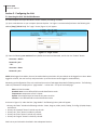
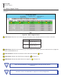
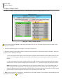
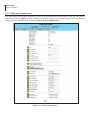
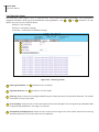
5.2 "Main > Status" Screen
The “Main > Status” screen (Figure 5.2) is a “read only” screen and displays the following information:
1
2
3
4
5
Figure 5.2 - "Main > Status" Screen
In the section entitled “TS” under an orange header, the following parameters about each output TS (transport stream) are
displayed:
1
TS Mapping: indicates the list of programs selected by the user to be assigned to TS (TS #1 thru 4). The program
information includes the PMT PID, Program number, Short Name, Major-minor channel number.
2
Bitrates: indicates the transport stream bitrate and the TS Bitrate (refer 2 of Section 5.7 for details).
In the section entitled “Output” under blue header, the following parameters about each output TS are displayed:
3
IP: indicates the encapsulation method, IP address, and the port number to which a TS is assigned.
4
QAM: indicates the RF channel number of the QAM output.
5
ASI: indicates the physical ASI OUT port number to which a TS is assigned.
14 HDE-4S-QAM
Instruction Manual
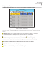
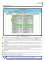
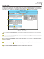
5.3. "Main > Program” Screen
The “Main > Program” screen (Figure 5.3) is a “user-configurable” screen to select the video/audio sources for each input
program:
1
4
3
2
5
Figure 5.3 - "Main > Program" Screen
1 Video Source: allows the user to select the type of the video source. Possible options are as shown in the table:
Program
Video Source
P1 & P2
HD-SDI #1 & 2
Component In #1 & 2
Composite In #1 & 2
P3 & P4
HD-SDI #3 & 4
Component In #3 & 4
Composite In #3 & 4
2 Audio Source: allows the user to select the type of the audio source. Possible options are Audio In #1 thru 4, Digital #1
thru 4, and HD-SDI #1 thru 4.
3 Video Resolution: indicates the resolution of the video input selected in 1
4 Video Bitrate: indicates the video bitrate as assigned in
above.
1 of Section 5.4.
5 Audio Bitrate: indicates the audio data rate as assigned in
1 of Section 5.5.
Refer "Real Time Application" under Section 2.2 before choosing the input program
combination.
Remember to click on the SAVE button to apply the new values/configurations.
HDE-4S-QAM 15
Instruction Manual
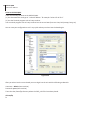
5.4 "Main > Video" Screen
The “Main > Video” screen (Figure 5.4) is a “user-configurable” screen to select the video encoder parameters for each
input program:
1
2
3
4
5
6
Figure 5.4 - "Main > Video" Screen
1
Bitrate: must enter the bitrate for each input video. It is recommended to ensure that the sum of the bitrates of the
input videos in a TS, does not exceed “TS Bitrate” selected on the "Main > TS Config" Screen (see 2 of section 5.7
for details). Setting higher bitrates will provide greater video detail in comparison to lower bitrates, but may reduce
the number of programs available within the TS. Typically HD programs use 12 to 17 Mbps and SD programs use 3 to 7
Mbps bitrates.
2
Closed Caption: is the process of passing the EIA-708 & EIA-608 Closed Captioning (CC) information and displaying the
CC text on television or other visual display. Possible options are Enabled and Disabled. The factory default value is
“Disabled”.
3
Video Filter Level: is a two-dimensional low-pass filter controlling the degree with which the input video is filtered.
Possible options are: Off (no filtering), On-Level 1, On-Level 2, On-Level 3, and On-Level 4 (highest filtering coefficient).
Level 1 filtering of the video will smoothen the sharp edges of the pixels and produce a softer image. The softer an
image, the less number of bits required to encode the image at the quantizer level.
4
Video Coding Mode: must select the Video Coding Mode. Possible options are: Frame and Field. The factory default
value is Frame.
5
GOP Size: The length between I-frames is known as the group of pictures (GOP) size. The factory default value is 15 i.e.
1 I-frame for every 14 non-I-frames. The range is 1 to 120.
6
Test pattern: is the video pattern that will be displayed on the output screen if no input video is present. Possible
options are: Color Bars, Black, Blue screen, and Red screen.
Remember to click on the SAVE button to apply the new values/configurations.
16 HDE-4S-QAM
Instruction Manual
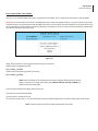
5.5 "Main > Audio" Screen
The “Main > Audio” screen (Figure 5.5) is a “user-configurable” screen where the following parameters associated with the
Dolby® Digital encoded stereo audio are configured and displayed for each audio input under a green header:
1
9
2
4
10
3
5
6
7
8
Figure 5.5 - "Main > Audio" Screen
1 Data Rate: allows the user to select the audio encoding bitrate in Kbps (kilobits per second). The range is 96 to 448 kbps.
The factory default value is 192 kbps that supports Audio Coding Mode 2/0:L, R.
NOTE: See Dolby Encoding guidelines for additional information.
2 Delay: allows the user to adjust the audio delay (-300 to 300 ms) to correct for input video/audio sync mismatch.
3 Sample Rate: indicates the input sampling rate of the encoder. The HDE-4S-QAM supports 48 kHz sampling rate.
4 Audio Coding Mode: also referred to as Channel mode. Indicates the number of main audio channels within the encoded
bitstream and also indicates the channel format. The unit supports 2/0:L,R= audio is a dual channel (Left & Right).
5 Dialog Normalization: behaves as an audio Automatic Gain Control (AGC) or Dynamic Range Control (DRC). It has the
ability to take different incoming audio levels and normalize them. The ability of the Dialog Normalization depends on the
configuration of the Dynamic Range Control. The HDE-4S-QAM allows you to adjust the normalization from -1 to -31 dB.
The typical value is -27 dB. This is based on the standard film audio formats which normally are between -25 and -31 dB.
HDE-4S-QAM 17
Instruction Manual
6 Dolby Surround Mode: indicates if the audio is two-channel Dolby or not. Possible options are:
Unspecified: indicates the decoder must determine the audio format by itself.
Disabled: indicates the audio is not encoded in surround mode.
Enabled: indicates the audio is encoded in surround mode.
7 Line Mode: allows the user to select the type of Dynamic Range Compression to be applied to signals that will be used as
direct audio feeds into a TV tuner or other receive devices. The factory default value is “None”.
8 RF Mode: allows the user to select the type of Dynamic Range Compression to be applied to signals that will be used for
retransmission on an RF carrier, and then fed into TV tuner or other receive devices at the end of the line. The factory
default value is "None".
Possible options for 7 and 8 are:
i) None: no dynamic range controls have been assigned.
ii) Film Standard: suitable for movies where the very low-level sounds are not to be amplified due to other
undesirable background noises that may become audible, but rather the peaks and valleys are normalized
instead. It has a null bandwidth of 10 dB (-31 to -21 dB) and can add up to 6 dB of boost for low levels and
attenuate high levels. The setting is used to quiet load shouting and amplifier whispers. See Dolby Encoding
guidelines for additional information.
iii) Film Light: is similar to “Film Standard” but with a null bandwidth of 20 dB (-41 to -21 dB) and can add up
to 6 dB of boost for low levels and attenuate high levels.
iv) Music Standard: suitable for program content that is mainly made up of music where the sound level is to
be normalized (reducing the loudness) to be consistent with other programs. It has a null bandwidth of 10 dB
(-31 to-21 dB) and can add up to 12 dB of boost for low levels and attenuate high levels. See Dolby Encoding
guidelines for additional information.
v) Music Light: similar to “Music Standard” but with a null bandwidth of 20 dB (-41 to -21 dB) and can add
up to 12 dB of boost for low levels and attenuate high levels.
vi) Speech: suitable for program content that is mainly made up of speech only and has a null bandwidth of
10 dB (-31 to -21 dB) for average speech and can add up to 15 dB of boost for low levels and attenuate high
levels. The setting is used to quiet load shouting and amplifier whispers. See Dolby Encoding guidelines for
additional information.
9
Left Channel Track: allows the user to select the location in the HD-SDI stream where the audio track resides. The default
location is “0” which is typically used for the left stereo channel. The range setting is 0 to 15.
10
Right Channel Track: allows the user to select the location in the HD-SDI stream that the audio track resides. The default
location is “1” which is typically used for the right stereo channel. The range setting is 0 to 15.
Remember to click on the SAVE button to apply the new values/configurations.
18 HDE-4S-QAM
Instruction Manual
5.6 "Main > TS Map" Screen
The “Main > TS Map” screen (Figure 5.6) is a “read and write” screen to assign programs to TS(s):
1
2
Figure 5.6 - "Main > TS Map" Screen
1 In the section entitled “Inputs” under the green header, the user can select the programs to be included in each
output TS as follows:
• Select the desired program; for example, P1 as shown in figure 5.6.
•Based on whether SPTS or MPTS output is required, select the MPTS or SPTS output stream number to which the
program is to be added; for example,
• If the user requires the output as SPTS and wants to add the above selection to SPTS output stream 3, then
select “TS: 3” (in top green header) and select the “Add” button in the bottom green header (see below for
details).
• If the user requires the output as MPTS and wants to add the above selection P1 and program P3 to MPTS
output stream 2, then select the programs P1 and P3, select “TS: 2” and select “Add” (see below for details).
NOTE: Input Programs 1-4 can be assigned to only one transport stream (TS) at a time. The software will not
allow a program to be selected twice. To move a program from one TS to another, first select the program
under the Output section (orange header) and then select the “Remove” button. Now under the Input section
(green header) select the program and the new TS: # (as above) and select “Add”.
• Add: Once the selection of programs is completed, select the "Add" button. This will add the selected programs to
the Output as shown in 2 of Figure 5.6.
HDE-4S-QAM 19
Instruction Manual
PIDs, Program Numbers, Channels or Channel Names must be unique in a MPTS
output stream. The user must edit the duplicated values using the “Main >TS Config”
Screen (see Section 5.7 for details). The duplicate values will be highlighted in red color under 2 of Figure 5.6
MPTS Output Stream ‘x’ and MPTS Output Stream ‘y’ may have same PIDs, Program Numbers,
Channels or Channel Names as each MPTS output stream is a unique stream.
STPS Output Stream ‘x’ and SPTS Output Stream ‘y’ may have same PIDs, Program Numbers,
Channels or Channel Names as each MPTS output stream is a unique stream.
2
In the section entitled “Output” under an orange header, the user can view the list of the programs that are present in
output TS:
TS# - IP/QAM/ASI: indicates the Transport Stream ID (refer 1 of Section 5.7 for details), and the type of outputs
assigned to a output TS i.e IP, QAM or ASI.
The fields under the “TS# - IP/QAM/ASI” under grey header, displays the list of the programs and the corresponding
total bitrate present in each output TS.
• Remove: The user can remove any of the programs from the current list by selecting it and clicking the "Remove" button.
20 HDE-4S-QAM
Instruction Manual
5.7 "Main > TS Config" Screen
The “Main > TS Config” screen (Figure 5.7) is a “read and write” screen to assign TS parameters:
1
5
3
2
6
7
8
4
9
11
Figure 5.7 - "Main > TS Config" Screen
10
HDE-4S-QAM 21
Instruction Manual
In the section entitled “Multiplexed MPTS Output Configuration”, the user can select and configure the following parameters
of the output TS:
1 TS ID: user must enter the identification number for the output TS. The range is 1 to 65535. The TS ID assigned must be
unique.
2 TS Bitrate: user must select the bitrate for the TS. Possible options are:
• QAM Modulator – Select this setting when using the QAM output of the encoder. The maximum bitrate will be
38.81 Mbps for QAM 256.
• 19.39 Mbps – Select this setting when the primary encoder output will be ASI for an ATSC application.
• 38.81 Mbps – Select this setting if an external QAM 256 modulator(s) will be used with the encoder’s ASI output(s).
3 Modulation Mode: user can select the modulation mode. Possible options are: Reserved, Analog, QAM64, QAM256, 8-VSB,
and 16-VSB.
4 Out of Band: an out-of-band (OOB) is a channel that is a combination of the forward and reverse OOB channels. When
a cable virtual channel is flagged as being out-of-band, it is carried on the out-of-band channel. The selections are either
Enable or Disable. When Enabled, the encoder assigns the OOB bit in the TS packet and labels the TS as out-of-band.
NOTE: As per the ATSC and Cable standards, the Modulation Mode and Out-of-Band fields are required
to be assigned in the TS packet. Selecting the above two fields would allow the TS packets to be compliant
with industry standards, but would not affect the input or output configuration of the HDE-4S-QAM.
In the section entitled “Output Mapping”, the user can select and configure the following parameters for each output TS
indicated by “TS# - IP/QAM/ASI” (see 2 of Section 5.6 for details), under gray header:
5 Input: indicates the list of the programs selected by the user that are included in the TS. It includes the Input program
number, video source, and audio source.
6 PID: indicates the PID value assigned to each stream. PID (Packet Identifier) values are embedded by the content provider in
the MPEG-2 stream to identify tables and programming packets.
The PID value must be unique in a MPTS output stream. If a duplicate PID exists, assign a different
PID in the range of 48 to 8176 (recommended range provided by the International Standards).
7 Program Number: user must enter a unique output program number for each program. PMT (Program Map Table) provides
information on each program present in the transport stream such as program_number, and the list of the elementary
streams (audio, video or data).
The Program Number must be unique in a MPTS output stream. If a duplicate Program Number
exists, assign a different number in the range of 1 to 65535.
8 Short Name: user may enter a short name for the channel. Up to 7 alphanumeric characters are allowed.
9 Major Channel: user may enter a major channel number for the output program. The range is 1 to 99 for Terrestrial and 1 to
999 for Cable.
22 HDE-4S-QAM
Instruction Manual
10 Minor Channel: user may enter a minor channel number for the output program. The range is 1 to 99 Terrestrial and 1
to 999 for Cable.
The channel number displayed on the screen is the combination of the major and minor
channels. Make sure that the major-minor channel pair is unique for each program on the MPTS
output. For example, if major channel = 6 and minor channel = 1, then the channel number
displayed would be 6-1.
MPTS Output Stream ‘x’ and MPTS Output Stream ‘y’ may have same PID, Program Number,
Short Name or Major-minor channel pair as each MPTS output stream is a unique stream.
11 Save: if duplicate values exist for PID, Program Number, Short Name or Major – Minor Channel Pair in a MPTS output
stream, when the SAVE button is clicked, the following pop-up window would appear accordingly: “Error! Duplicate
Program Numbers found”.
HDE-4S-QAM 23
Instruction Manual
5.8 "Main > IP" Screen
The “Main > IP” screen (Figure 5.8) is a “read and write” screen to assign the IP parameters for the TS:
1
2
3
4
5
6
Figure 5.8 - "Main > IP" Screen
1
Destination IP: allows user to assign the IP address of the equipment to which the GigE output is streamed to.
The Destination IP Address must be present before streaming occurs, otherwise the session is aborted. For
Multicast applications, the IP address must be in the range 224.0.0.0 through 239.255.255.255. For Unicast
applications, the IP address must be outside the above mentioned range.
2
Encapsulation: from the two available options (RTP & UDP) select the one that matches the protocol used by the
receiving equipment.
3
Destination Port: user must enter the IP Port of the receiving equipment. The factory default value is 50000. The range
is 1 to 65535. The port number assigned to each TS must be unique.
4
Source Port: user must enter the IP Port of the equipment that the input IP source is streamed from. The factory
default value is 50000. The range is 1 to 65535. The port number assigned to each TS must be unique.
NOTE: Port number is recommended to be from 49152 to 65535. Reason: Ports 1-1023 are
reserved and 1024-49151 are registered ports
5
Time to Live: is limit to the amount of time an IP packet can exist in an IP network. The value is set by the sender of the
packet, and reduced by every host on the route to packet’s final destination. If the Time to Live reaches zero before the
packet arrives at its final destination, then the packet is discarded. The purpose of this field is to avoid an undeliverable
packet from circulating on an IP network perpetually. The range is 1 to 255. Factory default value is 128.
6
Stuffing: Null packets are inserted to ensure that the TS bitrate assigned in 22 of Section 5.7 remains constant.
Possible options are Enable and Disable. It is advisable to Disable stuffing when only GigE output is used to help reduce
the traffic on the network.
Remember to click on the SAVE button to apply the new values/configurations.
24 HDE-4S-QAM
Instruction Manual
5.9 "Main > QAM" Screen
The “Main > QAM” screen (Figure 5.9) is a “read and write” screen to assign the QAM parameters to the TS:
1
2
3
4
5
6
7
8
9
10
Figure 5.9 - "Main > QAM" Screen
HDE-4S-QAM 25
Instruction Manual
1 Output Channel/Frequency: User must assign an RF channel number to the RF QAM output of the Quad-QAM module
(i.e. RF channel 2, as shown in Figure 5.9). The remaining three RF QAM channels will be automatically assigned to the
next adjacent channels (i.e. RF channels 3, 4, and 5). The range is NTSC channels 2 to 155.
The RF Channel number will be displayed on TV only if the source stream does not carry any
virtual channel number.
2 Output Control: turns each of the 4 RF channels On/Off.
3 CW Control: allows the user to switch the QAM output mode to CW (Continuous Waveform) which activates an analog
carrier at the selected channel’s center frequency comparable to the digital QAM output level. It is typically used when
only an analog signal level meter is available to measure the encoder’s output level during installation and servicing.
4 Final Output Level: selects the QAM RF output level for the combined output. The range is as shown in the table below
when configured for 1, 2, 3, or 4 QAM output channels.
# of RF/QAM Channel ON
Final Output Level Range (dBmV)
Default/Recommended
Value (dBmV)
1
52 to 60
60
2
48 to 58
56
3
56 to 46
54
4
44 to 54
52
5 Output QAM Mode: selects the desired QAM modulation mode. Possible options are: 64B, 256B, 16A, 32A, 64A, 128A,
and 256A. For most applications in the USA, the recommended QAM modulation mode is 256B.
6 Output QAM Map: selects the desired QAM Map (channel/frequency plan). Possible options are STD, IRC, and HRC.
7 Output QAM Data Rate: indicates the data rate depending on the selected QAM mode, for example 5.360500 Mbaud
for QAM 256B.
8 Output QAM Interleaver: indicates the interleaver value for the selected QAM mode.
9 Output QAM Alpha: indicates the Alpha value for the selected QAM mode.
10 QAM Lock State: indicates whether Quad-QAM module is working properly (locked) or not.
NOTE: The module may take a few seconds to lock when QAM output parameters are changed.
Remember to click on the SAVE button to apply the new values/configurations.
26 HDE-4S-QAM
Instruction Manual
5.10 "Main > Output" Screen
The “Main > Output” screen (Figure 5.10) is a “read and write” screen to assign each TS to their desired IP, QAM, and ASI
outputs:
1
2
3
4
5
Figure 5.10 - "Main > Output" Screen
In the section entitled “TS” under an orange header, the following parameters about each output TS are displayed:
1 TS Mapping: indicates the list of programs selected by the user to be assigned to TS (TS #1 thru 4). The program
information includes the PMT PID, Program number, Short Name, Major-minor channel number. For example, TS1
indicates a SPTS with TS ID 1. For program P1 [100 (1) (DVD) (3-1)] the following information is displayed:
100 – indicates the Program MAP Table (PMT) of the program.
1 – indicates the Program number as assigned in 7 of Section 5.7.
DVD – indicates the Short Name as assigned in 8 of Section 5.7.
3-1 - indicates the Major – minor channel number as assigned in 9 and 10 of Section 5.7.
101 V: Comp 1 – indicates that the input video source is Component 1 and the elementary stream PID is 101.
102 A: Audio In 1 – indicates that the input audio source is Audio In 1 and the elementary stream PID is 102.
2 Bitrates: indicates the transport stream bitrate and the TS Bitrate (refer 2 of Section 5.7 for details).
In the section entitled “Output” under blue header, the following parameters about each output TS are displayed:
3 IP: select the IP address, and the port number to which a TS is assigned (see 1 of Section 5.8 for details).
4 QAM: select the QAM RF channel number of the QAM output (see 2 of Section 5.9 for details).
5 ASI: select the physical ASI OUT port number to which a TS is assigned.
HDE-4S-QAM 27
Instruction Manual
5.11 "Main > Refresh" Tab
The “Main > Refresh” tab can be clicked while you are on any of the following sub-tabs screens: “Status”, “Program”, “Video”,
“Audio”, “TS Map”, “TS Config”, “IP”, “QAM”, and “Output”. When clicked, it will update all relevant fields/parameters of
the active screen as that information is retrieved from the HDE-4S-QAM in a real-time basis.
28 HDE-4S-QAM
Instruction Manual
5.12 "Network" Screen
The “Network” screen (Figure 5.11) is a read and write screen where the following parameters are displayed or configured:
1
3
5
7
9
2
4
6
8
10
11
12
13
14
15
17
19
16
18
20
21
22
Figure 5.11 - "Network" Screen
1 10/100 MAC Address: indicates the MAC Address of the “Remote Control 10/100” Port.
2 1 GigE MAC Address: indicates the MAC Address of the “Data Out 1GigE” Port.
3
Software Version: indicates the software version of the unit.
4 FPGA1 Version: indicates the current hardware version of the unit’s FPGA1 chipset.
5 FPGA2 Version: indicates the current hardware version of the unit’s FPGA2 chipset.
6 FPGA3 Version: indicates the current hardware version of the unit’s FPGA3 chipset.
7 FPGA4 Version: indicates the current hardware version of the unit’s FPGA4 chipset.
8 FPGA5 Version: indicates the current hardware version of the unit’s FPG5 chipset.
9 DDQ Version: indicates the current software version of the unit’s Quad-QAM output module.
HDE-4S-QAM 29
Instruction Manual
10 Hardware Version: indicates the current hardware version of the unit.
11 Serial Number: indicates the unit’s serial number.
12 Headend Name: a user-defined field to make identification easier.
13 Location: another user-defined field to make identification easier.
14 Login Timeout (Minutes): indicates the period of time before the unit logs itself out if there is no activity on the web
screens. Range is 5, 15, 30, or 60 minutes.
15 10/100 IP Address: see 14 of Section 5.12.1 for details.
16 10/100 Subnet Mask: see 15 of Section 5.12.1 for details.
17 10/100 Default Gateway: see 16 of Section 5.12.1 for details.
18 1 GIGE IP Address: see 17 of Section 5.12.1 for details.
Section 5.12.1 for details.
18
19 1 GIGE Subnet Mask: see of
1 GIGE Default Gateway: see of
section 5.12.1 for details.
19
20
21 Event Log Destination: see 20 of Section 5.12.1 for details.
22 Log Destination Port #: see 21 of Section 5.12.1 for details.
Remember to click on the SAVE button to apply the new values/configurations.
30 HDE-4S-QAM
Instruction Manual
5.12.1 "Admin.html" Hidden Screen
To change/modify the IP network parameters, as well as the Username and Password values for the unit, you must be
logged in to the unit as “Admin” to access a hidden screen shown in Figure 5.11.1 by typing the URL of the unit followed
by a forward slash and Admin.html, for example: http://172.16.70.1/Admin.html.
1
2
3
4
5
6
7
8
9
10
11
12
13
14
15
16
17
18
19
20
21
22
23
24
25
Figure 5.11.1 - ”Admin.html” Screen
HDE-4S-QAM 31
Instruction Manual
The following parameters can be modified:
Login: is the Administrator’s login (10 characters maximum). This login allows the user to make changes to any area of
1
the unit. The factory default Login is “Admin”. Login is case sensitive.
Current Password: is the Administrator’s Current Password (10 characters maximum). The factory default password is
2 “pass”. Password is case sensitive and will not be displayed.
3
New Password: used only if the user wants to change the current Administrator’s password. Must enter a new
password (10 characters maximum). Password is case sensitive and will not be displayed.
3
4 Confirm New Password: must enter the same password as entered in
does not match, an error will be displayed.
above. If password entered in 3 & 4 5 Guest Login: is the Guest login (10 characters maximum). This login allows the user to view the unit settings but does
not allow any changes. The factory default Guest Login is “Guest”. Login is case sensitive.
6 Current Guest Password: is the Current Guest Password (10 characters maximum). The factory default Guest password
is “pass”. Password is case sensitive and will not be displayed.
7 New Guest Password: used only if the user wants to change the current Guest password. Must enter a new password
(10 characters maximum). Password is case sensitive and will not be displayed.
8 Confirm Guest Password: must enter the same password as entered in
& 8 does not match, an error will be displayed.
7
above. If password entered in
7
9 Save Configuration Settings: allows the user to download and save the existing configuration of the unit in a .dat file format.
10 Choose File: allows the user to select the desired Config file from any location on the computer to be uploaded to the unit.
11 Load & Apply Configuration Settings: allows the user to upload a newly created file or update an existing file.
12 System Watchdog: when Enabled, automatically reboots the unit if, the Operating System stops working or the Status
LED turns stable green or Off. When Disabled, manual reboot is required in case of above events.
13 System Reboot: allows the user to reboot HDE-4S-QAM.
14 10/100 IP Address: is the static IP address that is assigned to the unit. It allows the user to access the unit via the web
interface. The factory default IP address is 172.16.70.1.
15 10/100 Subnet Mask: is the Subnet Mask address of the unit. It allows the user to access the unit from another
network via the web interface. The factory default Subnet Mask is 255.255.255.0.
16 10/100 Default Gateway: is the gateway address of unit. It allows the user to access the unit from another network
via the web interface. The factory default Subnet Mask is 172.16.70.254. 17 1 GIGE IP Address: is the static IP address assigned to the Gigabit Ethernet (GigE) port. The factory default value is
192.168.253.1.
18 1 GIGE Default Gateway: is the gateway address assigned to the Gigabit Ethernet (GigE) port. It allows the user to
access the IP output of the unit from another network. The factory default Subnet Mask is 192.168.253.254.
19 1 GIGE Subnet Mask: is the Subnet Mask address assigned to the Gigabit Ethernet (GigE) port. It allows the user to determine which subnet the GigE IP address belongs to. The factory default Subnet Mask is 255.255.255.0.
14
17
Make sure the IP address assigned to 10/100 IP Address and 1 GigE IP Address (see & above)
are in
different network address ranges or sub-networks.
Example: If the 10/100 IP Address = 172.16.70.100,
10/100 Subnet Mask = 255.255.255.0, and
1 GigE IP Address = 172.16.70.110,
then you will not be able to communicate with the unit as the Remote Control 10/100 and Data Out (1 GigE)
2
1
ports (see & of
Section 2.2 for details) belong to the same subnet.
Therefore, assign 1 GigE IP Address = 192.168.253.1 or 172.16.100.98 to ensure that the Remote Control 10/100 and
Data Out (1 GigE) ports belong to different address ranges (when using 192.168.253.1) or subnets (when using 172.16.100.98).
32 HDE-4S-QAM
Instruction Manual
20 Event Log Destination: is the IP address of the remote server, to which Syslog sends the activities recorded by HDE-
4S-QAM for monitoring and troubleshooting purposes. The factory default value is 172.16.70.2.
21 Log Destination Port #: is the Event Log Destination port to which a duplicate of the error messages created by the
unit can be forwarded for monitoring and troubleshooting purposes. The factory default value, which cannot be
modified, is 514.
22 Time Server IP: is the IP address for the Time Server from where the unit can obtain its clock reference (see Section 6.9
for details). The factory default value is 172.16.70.2.
23 Syslog Errors: is to enable/disable HDE-4S-QAM to forward error messages (in red font) to an SNMP syslog. The factory
default value is disabled.
24 Syslog Informational: is to enable/disable HDE-4S-QAM to forward information messages (in blue font) to an SNMP
syslog. The factory default value is disabled.
25 Syslog Feedback: is to enable/disable HDE-4S-QAM to forward feedback or confirmation messages (in green font) to an
SNMP syslog. The factory default value is disabled.
Remember to click on the SAVE button to apply the new values/configurations.
HDE-4S-QAM 33
Instruction Manual
5.13 "Time" Screen
The “Time” screen (Figure 5.12) is a “read and write” screen that allows you to set the current date and time for the HDE4S-QAM. To remain compliant with ATSC and cable standards, it is important to have the accurate date and time stamps. For
this reason, it is recommended to use the “NTPServer” option which allows the unit to automatically acquire time settings
from a "NTP Server" - you must enter the IP address of the time server (see 22 of Section 5.12.1 for details).
5
1
2
3
4
Figure 5.12 - "Time" Screen
1 In the section entitled “Time Adjustments”, the local time zone based on Coordinated Universal Time (UTC) can be set.
2 In the section entitled “Daylight Saving Time”, the user set the Daylight Saving Settings either manually or automatically
using the DST Adjustment option.
3 In the section entitled “NTP Server”, the user can enter the IP address of the NTP server to acquire the time directly
from the NTP Server.
4 The user can enter the IP address of the NTP server to acquire the time directly from the NTP Server when an internet
connection is available. (see 22 of Section 5.12.1 for details).
5 In the section entitled “Set Date & Time”, the user can manually enter the date and time.
34 HDE-4S-QAM
Instruction Manual
5.14 "Event Log" Screen
The “Event Log” screen (Figure 5.13) is a “read and write” screen where the following parameters can be displayed or
configured. The data in Error Log can be forwarded to a SysLog database – (see 23 , 24 , & 25 of Section 5.12.1 for
details). The lines are color coded as follows:
Red font = error message
Blue font = information message
Green font = confirmation or feedback message
1
2
3
4
5
Figure 5.13 - "Event Log" Screen
1 Event Log Destination: see 20 of Section 5.12.1 for details.
2
Log Destination Port: see 21 of Section 5.12.1 for details.
3
Clear Log: allows to clear the records generated during unit’s boot-up process and operation afterward. The records
are cleared if the unit loses power.
4 Lines to Display: allows the user to select the number of lines to be displayed. The unit supports up to 400 Mb of data
or approximately 65,000 lines. The range is 1 to 65,535.
5
Save Number of Displayed Lines: allows the user to save the error log on the screen. Please note that the error log
would be saved only on the screen and not on any database.
HDE-4S-QAM 35
Instruction Manual
Appendix A: Updating the Software Remotely
General background:
There are two different PROMs that need to be programmed in HDE-4S-QAM. They are called PROM1 and PROM2. Please
note not every software update requires both PROMs to be programmed. However, program both PROMs unless you get
a written notice with Release notes to do otherwise.
The total procedure takes about 10 minutes if you follow the steps below.
Step 1: FTP two files from your PC to HDE-4S-QAM.
Step 2: a) Update PROM1 with the specific command line.
b) Update PROM2 with the specific command line.
Step 1 : FTP two Files to HDE-4S-QAM:
FTP both files (EPCS_1_ver#.bin and EPCS_2_ver#.bin) into the HDE-4S-QAM server board (there are many ways to do this).
NOTE: a) The EPCS_1_ver#.bin is to program PROM1 and EPCS_2_ver#.bin is to program
PROM2.
b) All the commands are case sensitive
c) It is recommended to copy the EPCS_1_ver#.bin and EPCS_2_ver#.bin files in the root directory. i.e, My Computer > C:
From a command (DOS) prompt (you must be in the same folder as the EPCS files) enter:
ftp –A 172.16.70.1
At the FTP prompt enter the following commands:
{Please ensure that you have entered the “bin” command to confirm that you are FTPing the files as binary files.}
bin
put EPCS_1_ver#.bin
put EPCS_2_ver#.bin
bye
The above four commands may be automated by entering them in an ASCII text file (called ftpcmd, recommended but can
be any name) and executing the following:
ftp -A -s:ftpcmd 172.16.70.1
You can place the ftp command above in a batch file (.bat) then double click on the .bat file to perform the entire download
process.
36 HDE-4S-QAM
Instruction Manual
Telnet to HDE-4S-QAM:
There are two ways to telnet to the HDE-4S-QAM:
(1) Use Command line and type in “ telnet IP address “ for example “telnet 172.16.70.1”
(2) U
se the Terminal program such as Putty to telnet.
Use a terminal program such as Putty to telnet into the server board (can use Linux, DOS prompt, Putty, etc)
You can save your configurations so it’s very quick and easy to telnet into the board again.
Figure 5.14
After you telnet into the server board you must login into the unit with the following credentials:
Username = Admin (case-sensitive)
Password = pass (case-sensitive)
Then cd to the /home/ftp directory where the EPCS_x.bin files have been placed.
cd home/ftp
ls
HDE-4S-QAM 37
Instruction Manual
Step 2: Update PROM1 and/or PROM2:
Now you can use the field update utility (epcs) to program the EPCS PROMs. This is a custom utility that resides in HDE-4S-QAM.
Warning: Care should be taken at this time, if misspelled characters or letters are typed by accident, or you have missed to type the bin
command in Step 1, this could cause the HDE-4S-QAM Flash memory to be corrupted. The HDE-4S-QAM will try to reload the OS using
the corrupted file ten (10) times before it displays the following screen (Figure 5.15). You can recover from this situation by repeating the
procedure all over again from Step 1 above.
Figure 5.15
Ready: Please read the rest of this page once before typing the commands.
Update FPGA1 by programming EPCS1:
epcs –e1 EPCS_1_ver#.bin
Update FPGA2 by programming EPCS2: (if necessary)
epcs –e2 EPCS_2_ver#.bin
NOTE: Both EPCS PROMS can be programmed concurrently using two different terminal sessions
(logins). If you get errors during programming then DO NOT TURN OFF THE HDE-4S-QAM, just
repeat the epcs commands again.
The server board should now configure itself on power-up.
Two choices to reset the HDE-4S-QAM:
(1) Reset switch in the back of the unit.
(2) Use Telnet and type “epcs –c” this will automatically reboot the HDE-4S-QAM without a need for resetting with power switch.
NOTE: The boot-up process for HDE-4S-QAM is approximately 30 seconds.
38 HDE-4S-QAM
Instruction Manual
Appendix B: Viewing the IP output on a VLC Media player
To view the IP output from the HDE-4S-QAM on a VLC Media player in a computer or laptop, the procedure is divided into
two steps:
Step 1: Change the IP address of the computer
Step 2: Using the VLC Media Player
NOTE: Step 1 needs to be followed only if an unicast IP address is assigned in the “Destination IP” field on the
“Main > IP” screen (see 11 of Section 5.8 for details). If multicast IP address is used, then go to Step 2.
Step 1: Change the IP address of the computer
i) Change the IP address of the computer to match the “Destination IP” updated on the “Main > IP” screen (see 11 of
Section 5.8 for details and see Section 4 for instructions to change IP address of a computer).
Step 2: Using the VLC Media Player
i) Open VLC Media Player.
ii) Select Media → Open Network Stream.
iii) Under the “Network Protocol” field, enter the network address using any one of the formats depending on the
“Encapsulation” selected on the “Main > IP” screen (see 22 of Section 5.8 for details):
rtp://@<ip address>:<port no.>
eg: rtp://@239.10.10.31:50001
or
udp://@<ip address>:<port no.>
eg: udp://@192.168.253.100:50055
NOTE: For uni-cast, the <ip address> will be the IP address of the computer. For multicast, the <ip address> will
be the multicast address assigned under the “Destination IP” on “Main > IP” screen (see 2 of Section 5.8 for
details).
iv) Select Play.
Figure 5.16
Limited Warranty
Blonder Tongue Laboratories, Inc.
Limited Warranty
Blonder Tongue Laboratories, Inc. (BT) will at its sole option, either repair or replace (with a new or factory reconditioned product,
Seller will at its sole option, either repair or replace (with a new or factory reconditioned product, as Seller may determin e) any product manufactured or sold (or in
ascase
BT ofmay
determine)
any
product
manufactured
by BT
which
proves
totobemeet
defective
in factory
materials
or that
workmanship
orthe
fails
toof
Blonder
Tongue
Laboratories,
Inc.
(BT) iswill
at its in
sole
option,
repair
ororreplace
(with
a applicable
new or
reconditioned
as
BT
may
the
software,
licensed) by
Seller
which
defective
materials
oreither
workmanship
fails
the
specifications
are product,
in effect on
date
meet the
specifications
whichas are
on
theto
date
of shipment
orfor
such
other
specifications
asthemay
have
been
expressly
shipment
or such
other specifications
may
have
been expressly
agreed
upon
in writing:
(i)
aorperiod
of three
(3)
date
of original
purchase
determine)
any
product
manufactured
by in
BTeffect
which
proves
be defective
in materials
workmanship
oryears
fails from
to meet
the specifications
whichforareall
stock
hardware
than
specifically
referenced
herein
aof
shorter
warranty
period);
(ii)
for
a (i)
period
one
(1)ofyear
the
agreed
upon
in writing
(i)
fororthose
asuch
period
one
(1) year
thehaving
dateexpressly
original
purchase
such
shorter
period
of from
time
asdate
may
in
effect
on
theproducts
date
of (other
shipment
otherofspecifications
as from
maybelow
have
been
agreed
upon
in(or
writing
for aofperiod
one
(1) year
fromof
original
purchase,
with
respect
to agreement
all MegaPort™,specific
IPTV products,
test
equipmentsoftware
and fiber optics
receivers,
transmitters,
couplersto
and
integrated receiver/distribution
be
set
forth
in
the
license
to
the
particular
being
licensed),
with
respect
iCentral™
(hardware
and
the
date
of
original
purchase
(or
such
shorter
period
of
time
as
may
be
set
forth
in
the
license
agreement
specific
to
the
particular
software
being
amplifiers; (iii) for a period of one (1) year from the date of original purchase (or such shorter period of time as may be s et forth in the license agreement specific to
software)
and
all other
software
products
(including
software)
licensed
from
BT,embedded
(ii))Core
forProduct
asoftware)
period
of one
(1)
year
from
licensed),
with
respect
to iCentral™
(hardware
and
software)
and
all other
software
products
(including
licensed
from
BT,
(ii) )
the
particular
software
being
licensed
from
Seller) with
respect
to allembedded
software
products
licensed
from Seller
(other
than
Software)
that
is (a)
developed
the
date
purchase,
respect
all does
MegaPort,
IPTV
and
fiber
optics
receivers,
couplers
and
for
aaspecific
function
or application,
(b)with
complimentary
topurchase,
and
not
function
without
the Core
Product
Software,
and
(c) listed
with
a specific
model
number
and
for
periodof
oforiginal
one (1)
year
from the
date of
originalto
with
respect
toproducts
all MegaPort™,
IPTV
products,
and
fibertransmitters,
optics
receivers,
transmitters,
stock
number in
Seller’s Price List (“Non-Core
Software”);
(iv) for a TRAILBLAZER™,
period of ninety (90) RETRO-LINX™
days from the dateand
of original
purchase,
with
respect to
-serialized
integrated
receivers/distribution
amplifiers
(including
TWIN
STAR™
products)
asasnon
well
as
for
couplers
and
integrated
receiver/distribution
amplifiers
(including
TRAILBLAZER™,
RETRO-LINX™
and
TWIN
STAR™
products)
well
as
for
products
and accessories,
such as parts, satellite
sub-assemblies,
splitters
and all other
soldthree
by Seller
(other
than
Corethe
Product
Software
and Refurbished/Closeout
VideoCipher®
& DigiCipher®
receivers,
and
for
aproducts
period
years
from
date
of original
purchase,
with
DigiCipher
satellite
receivers,
(iii)(i)for
a period
three(iii)
(3)warranty
years
from
theof
date
of (3)
original
purchase,
with
respect
to allincluded
other
BT
Products)
not ®
otherwise
referred
to inand
clauses
through
(iii) of
above.
The
period
for
computer
programs
in machine-readable
form
in aproducts.
hardware
respect
to
all
other
BT
products.
Notwithstanding
the
foregoing,
in
some
cases,
the
warranty
on
certain
proprietary
sub-assembly
product,
which are essential
for the in
functionality
thereof
as specifically
stated in
the published
product specifications
(“Core Productby
Software”)
willvendors
be coincident
Notwithstanding
the foregoing,
some cases,
the warranty
on certain
proprietary
sub-assembly
modules manufactured
third-party
and
modules
manufactured
by
third
party
vendors
contained
in BTProduct
products
andis on
private-label
products
manufactured
with
the warranty
of the
applicable
hardware
product and
within
which
such Core
Software
installed.
contained
in
BTperiod
products
and
on
certain
private–label
products
manufactured
by third-parties
forcertain
resale by
BT are of shorter
duration
or otherwise
by third
parties
for standard
resale by BTlimited
are ofwarranty.
shorter In
duration
or otherwise
more
than
the
standardproprietary
BT limited
warranty. modules
In such
more
limited
than
such the
cases,
BT'swarranty
warranty
withlimited
respect
to Product
such
third-party
sub-assembly
Software
patches,
bugthe
fixes, updatesBT
or workarounds
do not extend
original
period
of
any Core
Software or
Non-Core Software.
cases,
BT’s
warranty
with
respect
to
such
third
party
proprietary
sub-assembly
modules
and
private-label
products
will
be
and private-label products will be limited to the duration and other terms of such third-party vendor's warranty. In addition, certain products,limited
that are
to the duration
and herein
other
of such third party vendor’s warranty. In addition, certain products, that are not manufactured
Notwithstanding
anything
toterms
the
not manufactured
but are
resold
by contrary,
BT, carry the original OEM warranty for such products. The limited warranty set forth in this paragraph does not
but are resold by BT, carry the original OEM warranty for that product. The limited warranty set forth in this paragraph does not
apply
to any
product
sold
bysoftware
BT, which
at
the properly
time of sale
constituted
a Refurbished/Closeout
(i)
Seller’s
obligation
for
thatwhich
when
installed
and used
does not a
substantially
conform
to the publish ed specifications in effect when the
apply
tosole
any
product
sold
by BT,
at the time
of sale
constituted
CloseoutProduct.
Product.
software is first shipped by Seller, is to use commercially reasonable efforts to correct any reproducible material non-conformity (as determined by Seller in its sole
discretion)
by providing
the
customer
with:
(a) telephone
or e-mail
access
to
non-conformance so
that Seller
can may
verifydetermine)
reproducibility,
a software
patch
(b)
BT will
its sole
option,
either
repair
or replace
replace
(with
orreport
factory-reconditioned
product,
as BT
any (b)
product
sold
by BTor
BTfix,
will
itsatsole
either
repair
or
(witha and
anew
new
or
factory
reconditioned
asdefective
BT mayexternal
determine)
any
product
bug
if at
available
or aoption,
workaround
to bypass
the
issue if available,
(c) where
applicable,
replacement orproduct,
damaged or
media, such
as
CD-ROM
which
at
the
time
of
sale
constituted
a
refurbished
or
closeout
item
(“Refurbished/Closeout
Product”),
which
proves
to
be
defective
in
materials
or
soldonby
BT the
which
at the
of sale
constituted a refurbished or closeout items (“Refurbished Product” and “Closeout Product”),
disk,
which
software
wastime
originally
delivered;
workmanship
or to
fails
meet the specifications
are in effect onorthe
datetoofmeet
shipment
such other specifications
haveonbeen
which proves
betodefective
in materialswhich
or workmanship
fails
the or
specifications
which areasinmay
effect
theexpressly
date of
(ii)
Seller upon
does not
warrant
that
use of any
software(90)
will days
be uninterrupted,
error-free,
free ofpurchase.
security vulnerabilities
the software
willin
meet
the cases
customer’s
agreed
writing,
forthe
a period
of ninety
from
the
date
of original
Notwithstanding
the
foregoing,
some
the
shipment
orinsuch
other
specifications
as may
have
beenfor
expressly
agreed
upon
in writing,
fororathat
period
ofsuitably
ninety
(90)
days
from
particular
requirements;
the customer’s
sole andproprietary
exclusive remedy
breachmodules
of this warranty
is, at Seller’s
option, tovendors
receive (a)
modified
software,
or
warranty
on
third
partyand
software
and
on certain
sub-assembly
manufactured
by third-party
and
contained
in BT
products
the
date
of
original
purchase.
Notwithstanding
the
foregoing,
in
some
cases,
the
warranty
on
third
party
software
and
on
certain
part thereof, or (b) comparable replacement software or part thereof;
and
on certainsub-assembly
private–label products
manufactured
by third-parties
resale
by BT and
are ofcontained
shorter duration
otherwiseand
moreon
limited
thanprivatethe BT
proprietary
modules
manufactured
by third for
party
vendors
in BTorproducts
certain
(iii)
Seller
retains allmanufactured
right,
title and interest
in andparties
to and ownership
all BT
software
(including
allduration
Core
Pro duct
Software and
Non-Core
Software)
any
and
limited
warranty
for
Refurbished/Closeout
Products.
suchofcases,
BT's
warranty
Refurbished/Closeout
Products
constituting
suchBT
third
partyall
label
products
by third
forInresale
by
are of
shorterfor
or otherwise
more
limited
thanincluding
the
limited
enhancements,
modifications
and updates
to the same;
and
software, third-party
proprietary
sub-assembly
modules
and private-label products will be limited to the duration and other terms of such third-party
warranty for Closeout Products. In such cases, BT’s warranty for Closeout Products constituting such third party software, third
vendor's
warranty.
addition,
notwithstanding
the
foregoing, modules
(i) certain
Refurbished/Closeout
Products
that
are and
not manufactured
(but
are
resold)
party
proprietary
sub-assembly
modules
and
private-label
products
will be
to
the duration
other
terms
of such
third
(iv)
in some
cases, the In
warranty
on certain
proprietary
sub-assembly
manufactured
bylimited
third-party
vendors
and contained
in Seller’s
products,
third
party
by
BT,vendor’s
carry theinwarranty.
original
OEM
warranty
for
such
which
may
be longer
or shorter
than
the Products
BT limited
warranty
forwill
Refurbished/Closeout
software
installed
certain of
Seller’s
products,
and
on products,
certain private–label
products
manufactured
by
third-parties
for resale
byare
Seller,
be of shorter duration
party
In addition,
notwithstanding
the foregoing,
(i) certain
Closeout
that
not
manufactured
(but
or
otherwise
more
limited
than
standardOEM
Seller
limitedare
warranty.
In such
cases, Seller's
respect
to such third-party
proprietary
Products.
All
sales
ofcarry
Refurbished/Closeout
Products
final.
are
resold)
by
BT,
thetheoriginal
warranty
for such
products,
whichwarranty
may bewith
longer
or shorter
than the BT
limitedsub-assembly
warranty
modules, third-party software and private-label products will be limited to the duration and other terms of such third-party vendor's warranty, if any. In addition,
for
Refurbished
or
Closeout
Products.
All
sales
of
Refurbished
or
Closeout
Products
are
final.
certain products, that are not manufactured by Seller, but are resold by Seller, may carry the original OEM warranty for such products, if any. The limited warranty
Toforth
obtain
service
thistowarranty,
thesold
defective
product,
a copy
of thea sales
receipt or otherProduct,
satisfactory
proof warranty
of purchase
and ais
set
above
does under
not apply
any product
by Seller,
which attogether
the time with
of sale
constituted
Refurbished/Closeout
the limited
for which
provided
in the
following
paragraph.
To obtain
service
under
thismust
warranty,
the defective
product,
together
withLaboratories,
a copy of the
sales
or other
satisfactory
brief
description
of the
defect,
be shipped
freight prepaid
to: Blonder
Tongue
Inc.,
Onereceipt
Jake Brown
Road,
Old Bridge,proof
New
of purchase
Jersey
08857. and a brief description of the defect, must be shipped freight prepaid to: Blonder Tongue Laboratories, Inc., One Jake
Seller will at its sole option, either repair or replace (with a new or factory-reconditioned product, as Seller may determine) any product sold by Seller which at the
Brown Road, Old Bridge, New Jersey 08857.
time of sale constituted a refurbished or closeout item (“Refurbished/Closeout Product”), which is defective in materials or workmanship or fails to meet the
This warranty
does notthat
cover
resulting
(i) use or
than
in strict
with manufacturer's
written
instructions,
(ii)
applicable
specifications
are damage
in effect on
the datefrom
of shipment
of installation
that productother
or fails
to meet
suchaccordance
other specifications
as may have been
expressly
agreed upon
in
writing
between
the
parties,
for
a period
ofthan
ninety
daysfrom
from the
date
of
purchase.
Notwithstanding
the for
egoing,misapplication
in some
the
warranty
on
This
warranty
does
cover
damage
resulting
(i)
ororiginal
installation
other
thancenter,
in strict
accordance
withcases
manufacturer’s
disassembly
or repair
bynot
someone
other
the (90)
manufacturer
or ause
manufacturer-authorized
repair
(iii)
misuse,
or abuse,
(iv)
certain
proprietary
sub-assembly
modules manufactured
by third-party
vendors
and contained
in Seller
products, third
party
software installed in certain ofrepair
Seller’s
written
instructions,
(ii) disassembly
or
repair
by someone
other
than
the
manufacturer
oror
a acts
manufacturer-authorized
alteration,
(v)
lack
of
reasonable
care
or
(vi)
wind,
ice,
snow,
rain,
lightning,
or
any
other
weather
conditions
of
God.
products, and on certain private–label products manufactured by third-parties for resale by Seller will be of shorter duration or otherwise more limited than Seller
center,
(iii) misuse,
misapplicationProducts.
or abuse,
(iv) cases,
alteration,
lack for
of reasonable
care orProducts
(vi) wind,
ice, snow,
lightning,
or
limited
warranty
for Refurbished/Closeout
In such
Seller's (v)
warranty
Refurbished/Closeout
constituting
such rain,
third party
proprietary
any
other
weather
conditions
or
acts
of
God.
sub-assembly
modules,
third
party
software,
and
private-label
products
will
be
limited
to
the
duration
and
other
terms
of
such
third-party
vendor's
warranty,
if
any.
OTHER THAN THE WARRANTIES SET FORTH ABOVE, BT MAKES NO OTHER WARRANTIES OR REPRESENTATIONS OF
In addition, notwithstanding the foregoing, (i) certain Refurbished/Closeout Products that are not manu factured (but are resold) by Seller, may carry the original OEM
ANY KIND,
EXPRESS OR
IMPLIED, ASbeTO
THE CONDITION,
DESCRIPTION,
FITNESS
FOR A PARTICULAR
PURPOSE,
warranty
such products,
if any, which may
longer or ABOVE,
shorter than Seller’s
limited
warranty
for WARRANTIES
Refurbished/CloseoutOR
Pr oducts.
All sales of
OTHERforTHAN
THE WARRANTIES
FORTH
MAKES
NO
OTHER
REPRESENTAMERCHANTABILITY,
AS TO ANY SET
OTHER
MATTER, ANDBT
SUCH
WARRANTIES
SUPERSEDE ANY ORAL
OR WRITTEN
Refurbished/Closeout
ProductsOR
are final.
TIONS OF ANYOR
KIND,
EXPRESS OR IMPLIED,
THE CONDITION,
DESCRIPTION,
FOR A PARTICWARRANTIES
REPRESENTATIONS
MADE AS
ORTO
IMPLIED
BY BT OR
BY ANY OFFITNESS
BT’S EMPLOYEES
OR
ULAR
MERCHANTABILITY
OR together
AS TOwith
ANY
OTHER
MATTER,
AND
SUCH
WARRANTIES
SUPERSEDE
To
obtain PURPOSE,
service under this
warranty,
the defective
product,
a copy
of theCATALOGS,
sales
receipt, serial
number
if applicable,
or otherMATERIALS.
satisfactory
proofIN
of
REPRESENTATIVES,
OR
IN ANY
OF BT’S
BROCHURES
MANUALS,
LITERATURE
OR OTHER
purchase
and a brief
description
of the
defect, must be shipped
freight prepaid to Seller at the
following
address:
One Jake
Brown
Road,BY
OldANY
Bridge,OF
NewBT’S
Jersey
ANY
ORAL
OR
WRITTEN
WARRANTIES
OR
REPRESENTATIONS
MADE
OR
IMPLIED
BY
BT
OR
ALL CASES, BUYER’S SOLE AND EXCLUSIVE REMEDY AND BT’S SOLE OBLIGATION FOR ANY BREACH OF THE
08857.
EMPLOYEES OR REPRESENTATIVES, OR IN ANY OF BT’S BROCHURES, MANUALS, CATALOGS, LITERATURE
WARRANTIES CONTAINED HEREIN SHALL BE LIMITED TO THE REPAIR OR REPLACEMENT OF THE DEFECTIVE
ORwarranty
OTHER
MATERIALS.
INperformance
ALL CASES,
BUYER’S from
SOLE
AND
EXCLUSIVE
REMEDY
AND
BT’S manufacturer's
SOLE OBLIGAThis
does
not cover failure of
or damage
(i) use
or installation
than
in strictBT
acc
ordance
PRODUCT
F.O.B.
POINT,
BT
IN ITSresulting
SOLE DISCRETION
SHALL other
DETERMINE.
SHALLwith
IN NO EVENT written
AND
TION FOR
ANYSHIPPING
BREACH
OFsomeone
THEASWARRANTIES
CONTAINED
HEREIN
SHALL
LIMITED
TO
THE REPAIR
OR
instructions,
(ii) disassembly
or repair by
other than the manufacturer
or a manufacturer-authorized
repairBE
center,
(iii) misuse,
misapplication
or abuse,
(iv)
UNDER
NO
CIRCUMSTANCES
BE
LIABLE
OR
RESPONSIBLE
FOR
ANY
CONSEQUENTIAL,
INDIRECT,
INCIDENTAL,
alteration,
(v)
exposure
to
unusual
physical
or
electrical
stress,
abuse
or
accident
or
forces
or
exposure
be
yond
normal
use
within
specified
operational
REPLACEMENT OF THE DEFECTIVE PRODUCT F.O.B. SHIPPING POINT, AS BT IN ITS SOLE DISCRETION SHALLor
PUNITIVE,
DIRECT
OR
SPECIAL
DAMAGES
UPON(vi)BREACH
OF WARRANTY,
BREACH
OF
CONTRACT,
environmental
parameters
set forth
in
productBASED
specifications,
lack
reasonable
care or (vii) wind,
sno
w, rain,
orNEGLIGENCE,
any other weather
DETERMINE.
BT SHALL
INapplicable
NO
EVENT
AND
UNDER
NOofCIRCUMSTANCES
BEice,
LIABLE
ORlightning,
RESPONSIBLE
FOR
conditions
acts of LIABILITY
God.
STRICTorTORT
OR OTHERWISE OR ANY OTHER LEGAL THEORY, ARISING DIRECTLY OR INDIRECTLY FROM
ANY CONSEQUENTIAL, INDIRECT, INCIDENTAL, PUNITIVE, DIRECT OR SPECIAL DAMAGES BASED UPON
THE SALE, USE, INSTALLATION OR FAILURE OF ANY PRODUCT ACQUIRED BY BUYER FROM BT.
BREACH
BREACH
OFSELLER
CONTRACT,
NEGLIGENCE,
TORT LIABILITY
OREXPRESS
OTHERWISE
OR
OTHER
THAN OF
THE WARRANTY,
WARRANTIES SET FORTH
ABOVE,
MAKES NO OTHER
WARRANTIESSTRICT
OR REPRESENTATIONS
OF ANY KIND,
OR IMPLIED,
AS
TO
THE OTHER
CONDITION,
DESCRIPTION,
FITNESS
FOR A PARTICULAR
PURPOSE,
OR AS TO
ANYSALE,
OTHER USE,
MATTER,
AND SUCH WARRANTIES
ANY
LEGAL
THEORY
ARISING
DIRECTLY
OR MERCHANTABILITY,
INDIRECTLY FROM
THE
INSTALLATION
OR
SET
FORTH
ABOVE
SUPERSEDE
ANY
OR WRITTEN
WARRANTIES
OR REPRESENTATIONS
IMPLIED
BY ANY
OF SELLER’S
All
claims for
shortages,
defects,
andORAL
non-conforming
goods
must be made
by the
customer inMADE
writingORwithin
five BY
(5) SELLER
days of OR
receipt
of merchandise,
FAILURE
OF
ANY
PRODUCT
ACQUIRED
BY
BUYER
FROM
BT.
EMPLOYEES
OR REPRESENTATIVES,
OR IN ANYall
OFmaterial
SELLER’Sfacts
BROCHURES
MANUALS,
CATALOGS,
LITERATURE
OR OTHER
MATERIALS.
ALL CASES,
BUYER’S
which writing
shall state with particularity
concerning
the claim
then known
to the customer.
Upon
any suchINclaim,
the customer
SOLE AND EXCLUSIVE REMEDY AND SELLER’S SOLE OBLIGATION FOR ANY BREACH OF THE WARRANTIES CONTAINED HEREIN SHALL BE LIMITED TO THE
shall
hold
the
complained
intact
duly protected,
for
a period
ofbe
up
to
sixtyby
(60)
days.
Upon
the request
offive
BT,(5)
the days
customer
shall
ship
All claims
forgoods
shortages,
and and
non-conforming
goods
must
Buyer
writing
within
of receipt
ofIN
REPAIR
OR REPLACEMENT
OF defects
THE of
DEFECTIVE
PRODUCT
F.O.B. SHIPPING
POINT,
AS made
SELLER
IN
ITS
SOLEin
DISCRETION
SHALL
DETERMINE.
SELLER
SHALL
such
allegedly
non-conforming
or
defective
goods,
freight
prepaid
BTANY
forCONSEQUENTIAL,
examination
by INDIRECT,
BT's
inspection
department
and
verification
ofany
the
NO
EVENT
AND UNDER
CIRCUMSTANCES
BE with
LIABLE
OR
RESPONSIBLE
FOR
INCIDENTAL,
PUNITIVE,
DIRECTUpon
OR SPECIAL
merchandise,
whichNOwriting
shall
state
particularity
all to
material
facts,
concerning
the
claim
then
known
to Buyer.
DAMAGES
BASED
BREACH
OF WARRANTY,
BREACH
OF CONTRACT,
STRICT TORT
LIABILITY
OR
OR ANY
OTHER LEGAL
defect.
BT,
at itsUPON
option,
will
replace
or issue
a credit
forNEGLIGENCE,
products
determined
to be
defective.
BT's
liability
and
responsibility
for
such complaint,
Buyer
shalleither
holdrepair,
the goods
complained
of intact
and duly
protected,
for
a period
ofOTHERWISE
up
to sixty
(60)
days.
Upon
THEORY, ARISING DIRECTLY OR INDIRECTLY FROM THE SALE, USE, INSTALLATION OR FAILURE OF ANY PRODUCT ACQUIRED BY BUYER FROM SELLER.
defective
products
is specifically
to the allegedly
defective item
or to credit towards
the original
billing.
All such
replacements
by examination
BT shall be made
the request
of BT,
Buyer shalllimited
ship such
nonconforming
or defective
goods,
freight
prepaid
to BT for
by
free
ofinspection
charge
f.o.b.
the
delivery
point
called forgoods
inofthe
original
order.
Products
for inwhich
replacement
has
been
under
provisions
ofwriting
this
BT’s
department
verification
the
defect.
BT,
option,
will
either
repair,
replace
or issue
a the
credit
forwhich
products
All
claims
for shortages,
defects,
andand
non-conforming
must
be made
by at
theits
customer
writing
within
five (5)
days
of made
receipt
of merchandise,
shall
state
withbecome
particularity
all material
concerning
claim then known
to
the customer.
Upon any
such
thelimited
customer
hold
the
goods
complained
clause
shall
the property
offacts
BT.
Underand
nothe
circumstances
are
to products
be returned
BTclaim,
without
BT's prior
written
authorization.
determined
to be defective.
BT’s
liability
responsibility
forproducts
defective
is to
specifically
toshall
the
defective
item
orBT
to
of intact and duly protected, for a period of up to sixty (60) days. Upon the request of Seller, the customer shall ship such allegedly non-conforming or defective
credit towards
original
billing. All such
by BTAny
shall
be made
free of
ofacharge
delivery
point
called for
in
reserves
the right the
to scrap
any unauthorized
returnsreplacements
on a no-credit basis.
actions
for breach
contractf.o.b.
of salethe
between
BT and
a customer
must
goods, freight prepaid to Seller for examination by Seller's inspection department and verification of the defect. Seller, at its option, will either repair, replace or issue
the
original
order.
Products
which
replacement
been
madeoffor
under
the
provisions
of this
shall
the
property
commenced
by the
customer
within
thirteen
(13) liability
monthshas
after
the cause
action
has products
accrued.isAspecificall
copy
of yclause
BT's
standard
terms
anditem
conditions
of
abe
credit
for products
determined
to for
be defective.
Seller's
and
responsibility
defective
limited
to thebecome
defective
or to credit
of BT.including
Under
no
circumstances
are
toshall
beBTreturned
toofBT
without
BT’s
priorpoint
written
BT
reserves
the
towards
the
original
All warranty,
such replacements
by Seller
beupon
made request.
free
charge
f.o.b.
calledauthorization.
forcovering
in the original
order.
Products
forright
which
sale,
thebilling.
limited
is products
available
from
Copies
ofthe
thedelivery
limited
warranties
third-party
proprietary
subreplacement
has been
madeprivate-label
under the
provisions
this clause shall
property
ofbreach
Seller.
Under
no circumstances
are be
products
to be
to Seller
to scrap modules
any
unauthorized
returns
on aofmanufactured
no-credit
basis.
Any the
actions
of from
this
contract
must
commenced
Buyer
assembly
and
products
bybecome
third-parties
arefor
also
available
BT on request.
DigiCipher
®returned
is a by
registered
without Seller's prior written authorization. Seller reserves the right to scrap any unauthorized returns on a no-credit basis. Any actions for breach of a contract of
within
thirteen
(13)
months
after
the
cause
of
action
has
accrued.
A
copy
of
BT’s
standard
terms
and
conditions
of
sale,
including
trademark
Motorola
(Revmust
0509)
sale
betweenofSeller
and a Corp.
customer
be commenced by the customer within thirteen (13) months after the cause of action has accrued. A copy of Seller's
the limited
is available
from the
BTlimited
uponwarranty,
request.is Copies
the
limited
warranties
thirdwarranties
party proprietary
substandard
terms warranty,
and conditions
of sale, including
available of
from
Seller
upon request.
Copiescovering
of the l imited
covering third-party
proprietary
modules
and private-label
products
manufactured byby
third-parties
may also
available
from Seller
(Rev 0713)
assemblysub-assembly
modules and
private
label products
manufactured
third parties
are be
also
available
fromonBTrequest.
on request.
VideoCipher®
& DigiCipher® are registered trademarks of Motorola Corp.
One Jake Brown Road
Old Bridge, NJ 08857-1000 USA
(800) 523-6049 • (732) 679-4000 • FAX: (732) 679-4353
www.blondertongue.com