1
MeshBee®
Open Source ZigBee RF Module
CookBook
© 2014 Seeed Technology Inc.
www.seeedstudio.com
© 2014 Seeed Technology Inc.
MB_2014_D02
1
Doc Version
v0.1
Date
2014/05/07
© 2014 Seeed Technology Inc.
Author
Remark
Created
MB_2014_D02
2
Table of contents
Table of contents
Chapter 1: Getting Started ......................................................................................................... 4
1.0 Introduction ............................................................................................................... 4
1.1 Installing IDE ............................................................................................................. 5
1.2 Setting up the MeshBee .............................................................................................. 8
1.3 Upgrade firmware ..................................................................................................... 10
1.4 Setting up the network ...............................................................................................11
Chapter 2: Example of Mode Operation ................................................................................. 13
2.1 AT mode .................................................................................................................... 13
Additional Documentation ..................................................................................... 14
2.2 API Mode.................................................................................................................. 15
Remote led blink example ..................................................................................... 15
Sending Data packets example .............................................................................. 18
2.3 MCU Mode ............................................................................................................... 21
Mechanism ............................................................................................................. 21
Additional documentation: .................................................................................... 23
Blink example in AUPS ......................................................................................... 23
2.4 Data Mode ................................................................................................................ 24
Chat example ......................................................................................................... 24
© 2014 Seeed Technology Inc.
MB_2014_D02
3
Introduction
Chapter 1: Getting Started
1.0 Introduction
MeshBee® is a 2.4 GHz wireless zigbee RF module. It use microchip JN516x from NXP that
enables several different flvors of standards-based zigbee mesh networking. Our released firmware
fully supports Zigbee Pro stack. You can use MeshBee® in three different ways:
Master Mode: the factory firmware warps the complicated Zigbee stack operation into a few
easy to use serial commands(AT commands).
Slave Mode: for a complex mesh network, a host application can send API frames to the
MeshBee® that contain short address and payload information instead of using AT command.
Transparent Mode: MeshBee® can also work as a transparent serial communication node that
can be part of a simple point-to-point connection. When operating in this mode, the modules act as a
serial line replacement - all UART data received through UART1 is directly send to a specified
remote node.
© 2014 Seeed Technology Inc.
MB_2014_D02
4
Installing IDE
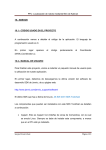
1.1 Installing IDE
NXP provides full-scale development environment, tools and documents. The development
environment consists of the SDK toolchain and the ZigBee stack SDK. Please visit NXP's website to
get some detailed description: http://www.nxp.com/techzones/wireless-connectivity/smart-energy.html
Note: MeshBee’s factory firmware is developed on top of the
smart energy profile.
To create the development environment, perform these steps:
1) Install JN-SW-4041 SDK Toolchain to default disk: C:/
2) Install JN-SW-4064 ZigBee Smart Energy SDK to default disk: C:/
© 2014 Seeed Technology Inc.
MB_2014_D02
5
Installing IDE
Note: The developing toolchain supports windows only. For
Linux and Mac users, a windows VM is recommended.
When finished the installing, you can test the tool chain if you are not sure whether it is
successful or not. Perform these steps:
1) Clone the latest firmware source code from github.
2) Copy the source code folder to C:/Jennic/Application/.
3) Open Jennic Bash Shell.
4) Type these shell commands:
cd MeshBeeMasterBranch
cd build
./build.sh
If three binary files are generated successfully, congratulations, you have finished all the
© 2014 Seeed Technology Inc.
MB_2014_D02
6
Installing IDE
preparation work.
Open eclipse IDE and import the project, you can catch a glimpse of the firmware:
© 2014 Seeed Technology Inc.
MB_2014_D02
7
Setting up the MeshBee
1.2 Setting up the MeshBee
To assemble your experimental environment, perform the following steps:
1) Step1: Insert MeshBee into the socket of UartBeeV5;
2) Step2: Connecting UartBeeV5 with PC by USB port;
© 2014 Seeed Technology Inc.
MB_2014_D02
8
Setting up the MeshBee
Note: Switch the SW to “3V3” and SW3 to “Prog” position at
first.
© 2014 Seeed Technology Inc.
MB_2014_D02
9
Upgrade firmware
1.3 Upgrade firmware
A wireless network comprises a set of nodes that can communicate with each other
by means of radio transmissions according to a set of routing rules (for passing messages between
nodes). ZigBee network includes three types of node:
1) Coordinator: This is the first node to be started and is responsible for forming the network by
allowing other node to join the network through it.
2) Router: This is the node with routing capability, and is also able to send/receive data.
3) End device: Only capability to send/receive data.
Different device role should burn different image. Burn the latest firmware using JN51xx Flash
Programmer. Four steps are required as below:
© 2014 Seeed Technology Inc.
MB_2014_D02
10
Setting up the network
1.4 Setting up the network
Zigbee network lifecycle
Normally, MeshBee will form the Network automatically. If a router or end device failed to join
network, you can use command “ATRS” to rescan and perform network actions again.
© 2014 Seeed Technology Inc.
MB_2014_D02
11
Setting up the network
© 2014 Seeed Technology Inc.
MB_2014_D02
12
Example of Mode Operation
Chapter 2: Example of Mode Operation
MeshBee has four different types of mode: AT, API, DATA, MCU, illustrated in figure below:
No matter which mode MeshBee works in, input “+++” can go back to AT command mode.
2.1 AT mode
The AT commands that MeshBee radios use for interactive are a descendant of hayes command
set. Every AT command starts with “AT”, and followed by two characters that indicate which
command is being executed, then by some optional configuration values.
To communicate with MeshBee from Win7, we will use SecureCRT. In CoolTerm on a Mac,
the procedure works pretty much the same.
© 2014 Seeed Technology Inc.
MB_2014_D02
13
Example of Mode Operation
Note: The baud-rate must be set to 115200 in SecureCRT.
Make sure MeshBee works in AT mode.
Use AT commands is very easy. Here are the steps:
1) Input “+++” to go to AT command mode.
2) Wait for a MeshBee “ok” response.
3) To read a register, just typing an AT command.
4) To set a register, type an AT command followed by the register value.
AT command contain three different types:
Additional Documentation
For more information about the AT command operations, please refer to the MeshBee User’s
manual v0.1.
© 2014 Seeed Technology Inc.
MB_2014_D02
14
Example of Mode Operation
2.2 API Mode
API is simply a set of standard interfaces created to allow other MCU to interact with MeshBee.
For our purposes, API supports local operation and remote operation. For example, a host application
can send an “ATIO” frame to Coordinator A, A will set its GPIO when it receives this frame. The
most important thing to note is that APIs are specifically engineered to enable MeshBee to talk
efficiently to other MCU. The target of API-mode is to transmit highly structured data quickly and
reliably.
Remote led blink example
Sending commands over the wireless network to control the remote device is kind of
exhilarating, it is something you can accomplish in API mode.
Some kinds of AT commands can also be sent wirelessly for execution on remote device. Here,
we implement a remote IO control demo.
Hardware list:
Arduino
X1
MeshBee
X2
XBee shield
X1
UartBeeV5
X1
© 2014 Seeed Technology Inc.
MB_2014_D02
15
Example of Mode Operation
Install hardware like that:
1) Connect Arduino with MeshBee’s Coordinator through UART.
2) Connect MeshBee’s Router with UartBeeV5.
Arduino sketch:
/*
Remote LED control sketch
Send remote AT request frame to Coordinator(short address is 0x0000)
Router should enter API mode at first
On/Sleep Led on remote device will blink
*/
#include <Arduino.h>
#include <Serial.h>
/* LED Pin */
int led = 13;
/* declaration */
void remoteATIO_Off();
void remoteATIO_On();
© 2014 Seeed Technology Inc.
MB_2014_D02
16
Example of Mode Operation
void setup() {
pinMode(led, OUTPUT);
/* open the serial port at 115200 bps */
Serial.begin(115200);
}
void loop() {
remoteATIO_On();
digitalWrite(led, LOW);
delay(500);
remoteATIO_Off();
digitalWrite(led, HIGH);
delay(500);
}
/* Turn off remote Led */
void remoteATIO_Off()
{
Serial.write(0x7e); //start delimiter
Serial.write(0x0d);
//length
Serial.write(0x17);
//API identifier: remote AT require
Serial.write(0xec); //frame ID
Serial.write(0x00);
//option
Serial.write(0x70);
//AT cmd index
Serial.write(0x09);
//IO pin No
Serial.write(0x00);
//State: Off
Serial.write(0x00);
//none
Serial.write(0x00);
//none
Serial.write(0x00);
//none
Serial.write(0x00);
//none
Serial.write(0x00);
//none
Serial.write(0x00);
//none
Serial.write(0xc6); //unicast address low
Serial.write(0x71);
//unicast address high
Serial.write(0x9c); //check sum: payload byte[4-16]
© 2014 Seeed Technology Inc.
MB_2014_D02
17
Example of Mode Operation
}
/* Turn on remote Led */
void remoteATIO_On()
{
Serial.write(0x7e);
Serial.write(0x0d);
Serial.write(0x17);
Serial.write(0xec);
Serial.write(0x00);
Serial.write(0x70);
Serial.write(0x09);
Serial.write(0x01); //State: On
Serial.write(0x00);
Serial.write(0x00);
Serial.write(0x00);
Serial.write(0x00);
Serial.write(0x00);
Serial.write(0x00);
Serial.write(0x00);
Serial.write(0x00);
Serial.write(0x9d);
}
Sending Data packets example
Now that you may understand how API mode works. It’s pretty simple to write your own MCU
code to work with API mode.
Sometimes, you want to send some data packet in your protocol. For example, in many sensor
network applications, the data samples are a series of data set, like:
typedef struct
{
uint8 verifyByte;
//verify, avoiding mistakes when take serial transmission
uint8 dataType;
// maybe temperature or humility
uint16 dataPointCnt;
// number of data point
© 2014 Seeed Technology Inc.
MB_2014_D02
18
Example of Mode Operation
int16 datapoint[DATA_POINT_NUM];
//a series of data points
}tsDataStream;
API data packet can meet your demands.
Arduino sketch:
/*
Sending data packet demo
Coordinator will receive “seeed” in its uart.
*/
#include <Arduino.h>
#include <Serial.h>
/* LED Pin */
int led = 13;
/* declaration */
void sendDataPacket();
void setup() {
pinMode(led, OUTPUT);
Serial.begin(115200);
// open the serial port at 115200 bps:
}
void loop() {
sendDataPacket();;
digitalWrite(led, LOW);
delay(500);
sendDataPacket();
digitalWrite(led, HIGH);
delay(500);
}
/* Send data packet */
void sendDataPacket()
© 2014 Seeed Technology Inc.
MB_2014_D02
19
Example of Mode Operation
{
Serial.write(0x7e); //start delimiter
Serial.write(0x19);
//length
Serial.write(0x02);
//Api identifier API_DATA_PACKET
Serial.write(0xec); //frameId, any number
Serial.write(0x00);
//option 0x00 indicate NO-ACK
Serial.write(0x06);
//data length: 2 byte
/* Has 20 bytes to hold your data */
Serial.write(0x73);
// data[0] = 's'
Serial.write(0x65);
// data[1] = 'e'
Serial.write(0x65);
// data[2] = 'e'
Serial.write(0x65);
// data[3] = 'e'
Serial.write(0x64);
// data[4] = 'd'
Serial.write(0x00);
// none
Serial.write(0x00);
Serial.write(0x00);
Serial.write(0x00);
Serial.write(0x00);
Serial.write(0x00);
Serial.write(0x00);
Serial.write(0x00);
Serial.write(0x00);
Serial.write(0x00);
Serial.write(0x00);
Serial.write(0x00);
Serial.write(0x00);
Serial.write(0x00);
Serial.write(0x00);
Serial.write(0x00);
// unicast address Low, we send to 0x0000(Coordinator)
Serial.write(0x00);
// unicast address High
Serial.write(0xf8); // checkSum: sum of payload
}
In order to taking advantage of the API mode, a software library written by C was developed.
This library presents the internal information in a human-friendly format. You can package the API
frame by functions it provides.
© 2014 Seeed Technology Inc.
MB_2014_D02
20
Example of Mode Operation
2.3 MCU Mode
In order to simplify the development of application for user, we create an Arduino-ful user
programming space(AUPS). The most important thing to note is AUPS is not a real Arduino because
it doesn’t support Arduino-IDE. We only present two Arduino style functions:
/* arduino setup */
void arduino_setup(void)
{
/**/
}
/*arduino loop*/
void arduino_loop(void)
{
/**/
}
Mechanism
Experienced C/C++ programmers may wonder where the program’s main() entry point function
has gone. It’s there, but it’s hidden under the covers by a task of JenOS.
A task called “Arduino_Loop” was running on background. There are several other tasks created
on MeshBee too. So Arduino_Loop should release CPU periodically to let other task use it.
A software timer was created to activate Arduino_Loop. You must set repeat time in
arduino_setup() by calling setLoopIntervalMs at first. The repeat time is similar to crystal oscillator
frequency of Arduino.
void ups_init(void)
{
/* Init ringbuffer */
UPS_vInitRingbuffer();
//init suli
suli_init();
//init arduino sketch with arduino-style setup function
arduino_setup();
//start arduino loops, Arduino_LoopTimer is bound with Arduino_Loop task
© 2014 Seeed Technology Inc.
MB_2014_D02
21
Example of Mode Operation
OS_eStartSWTimer(Arduino_LoopTimer, APP_TIME_MS(1), NULL);
}
OS_TASK(Arduino_Loop)
{
if(E_MODE_MCU == g_sDevice.eMode)
{
/* Back-Ground to search AT delimiter */
uint8 tmp[AUPS_UART_RB_LEN];
uint8 *Device = NULL;
uint16 DeviceId = 0;
uint32 avlb_cnt = suli_uart_readable(Device, DeviceId);
uint32 min_cnt = MIN(AUPS_UART_RB_LEN, avlb_cnt);
/* Read,not pop,make sure we don't pollute user data in AUPS ringbuffer */
vHAL_UartRead(tmp, min_cnt);
if (searchAtStarter(tmp, min_cnt))
{
/* Set AT mode */
setNodeState(E_MODE_AT);
suli_uart_printf(Device, DeviceId, "Enter AT Mode.\r\n");
/* Clear ringbuffer of AUPS */
OS_eEnterCriticalSection(mutexRxRb);
clear_ringbuffer(&rb_uart_aups);
OS_eExitCriticalSection(mutexRxRb);
}
else
{
arduino_loop();
}
}
if(_loopInterval > 0)
{
OS_eStartSWTimer(Arduino_LoopTimer, APP_TIME_MS(_loopInterval), NULL);
} else
{
© 2014 Seeed Technology Inc.
MB_2014_D02
22
Example of Mode Operation
OS_eActivateTask(Arduino_Loop);
}
}
Write your own code in “ups_arduino_sketch.c”, then compile and upload the image to
MeshBee.
In AT mode, using “ATMC” to enter MCU mode.
Additional documentation:
For more information about the function list that AUPS can call, please refer to the MeshBee
User’s manual v0.1.
Blink example in AUPS
/*
Blink demo in AUPS
UartBeeV5’s Sleep/On Led will blink
*/
IO_T led_io;
int16 state = HAL_PIN_HIGH;
void arduino_setup(void)
{
setLoopIntervalMs(1000);
//set loop period
suli_pin_init(&led_io, 9);
//init led
suli_pin_dir(&led_io, HAL_PIN_OUTPUT);
}
void arduino_loop(void)
{
suli_pin_write(&led_io, state);
//set led
if(state == HAL_PIN_HIGH)
state = HAL_PIN_LOW;
else
state = HAL_PIN_HIGH;
}
© 2014 Seeed Technology Inc.
MB_2014_D02
23
Example of Mode Operation
2.4 Data Mode
When operating in Data mode, the modules act as a serial line. All UART data received through
the UART1 is transmitted to a specified remote device.
To use a transparent connection, take the following steps:
1) Set unicast address:
ATDAxxx
2) Enter Data Mode:
ATDT
Chat example
Coordinator say HI to Router:
Router receives Coordinator’s greeting and reply to it:
© 2014 Seeed Technology Inc.
MB_2014_D02
24
Example of Mode Operation
Coordinator receives Router’s reply:
© 2014 Seeed Technology Inc.
MB_2014_D02
25