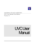
1
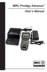
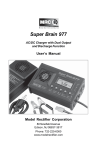
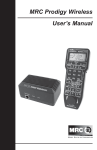
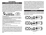
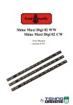
MRC Prodigy Elite User’s Manual
Introduction
Thank you for purchasing MRC’s Prodigy Elite DCC (Digital Command Control) system. You
now own one of the most advanced, easy to use DCC systems available. It comes as a
complete system with a Command Station (base unit), that incorporates a backlit L.C.D. on the
front, that displays, track voltage, current draw, and time. It also comes with a power supply
and Backlit LCD Cab/Handheld with cable. The MRC Prodigy Elite DCC system will enhance
the enjoyment of your train layout for many years to come. Here at MRC, we pride ourselves in
giving you the most advanced, reliable and easy to use DCC train controls. With up to 9,999
addresses available and use of up to 99 Cabs, you can expand your railroad empire as much
as you desire. From a beginner’s 4x8 layout to a massive club layout, the Prodigy Elite gives
you everything you want.
It is also compatible with all handhelds from the Prodigy Advance, Advance Squared, Express,
and Wireless Add-0n Set, (item no. 0001412). (Do not Use AD493 style handhelds!)
Your New Elite DCC System comes with the following items:
1.
10 amp/15 volt D.C. power supply with U.S.A. style wall cord.
2.
Command Console/Base Unit.
3.
Cab/Handheld with backlit display.
4.
Cab/Handheld cable.
Nothing else is required to get your system up and running.
All you need are decoder Equipped Locomotives.
1|Page
Warning
If you have more than one cab please make sure each cab has its own unique cab
number (all cabs are set to cab #1 at factory). Never use cabs with same cab number
together. It may damage the system.
Note:
Although there are Quick-start instructions on the back of the Cab/Handheld, please
read these instructions thoroughly to better understand and enjoy your Prodigy Elite
DCC system.
DCC Basic Background
A DCC system consists of a DCC Command Station that sends DCC commands to your layout
and DCC decoders installed in your locos that receive the DCC commands. Each decoder
equipped loco has its own address. Each decoder receives DCC commands but only follows
those commands matching its address. No more multiple blocks and no more multiple power
packs. With DCC, you can run different locos with different speeds and directions all on the
same track. You can also turn on/off the loco’s headlight and activate sounds if your loco is
equipped with a sound decoder. Please visit our website at www.modelrectifier.com for more
information about other DCC products.
Please read this manual and your decoder manual carefully before installing and operating
your DCC system.
Note:
The Prodigy Elite does not support NON-decoder equipped or analog locos. MRC’s earlier
DCC systems do support running analog locos. However, running analog locos will
dramatically slow the response time of your DCC system. Therefore, our new Prodigy Elite
does not support this old feature.
2|Page
Info
For more information on DCC or Prodigy Elite, visit the DCC Resources section of our web site at
www.modelrectifier.com or visit the National Model Railroad Association’s website at
www.nmra.org.
Specifications and Features
Input: 15-16 volts DC, 10 Amps. It comes with a universal switching power supply (good for USA and
Europe).
Output: DCC signal with 14.5 V amplitude at 10 amps, for all scales
Large layouts may need to be divided into power districts using power boosters, such as MRC’s
0001521 8 amp district booster.
Maximum Current: 10 Amps
Maximum number of Cabs: Use up to 99 Cabs (see page 2-4)
Address Capability: 2-digit (1-127) or 4-digit (1-9,999)
Speed Steps: 14/28/128
Accessory Functions: 28 (F0-F28)
Advanced and Universal Consisting
Program Loco on Program Track
Program Loco on Main Track
Read Loco on Program Track
Adjustable Amp Output for Your Scale or Power Requirements
Backlit Display on Console for Fast Clock, Volts and Amps
LED Light Array on Console Monitors System Status
System Menu Summary Chart
Most functions are initiated by pressing their associated keys. However, there are ten functions initiated
by pressing the SYS key followed by a numeric key (0-9). The following table summarizes these ten
functions and the information about each function is found in the manual.
Buttons
SYS + 0
SYS + 1
SYS + 2
SYS + 3
SYS + 4
SYS + 5
SYS + 6
SYS + 7
SYS + 8
SYS + 9
SYS + SHIFT
Function
Clear Routes
Set Time
Set Time Ratio
Yard Mode On/Off
Set Time Mode AM/PM/Military
Set Routes
Set Cab/Handheld Address
Set Last Handheld Allowed to Program Locos on Main Track
Set Last Handheld Allowed to Program Locos on Program Track
Set Total Number of Operational Cab/Handhelds
Set Current Output Level (Range is 1 to 9)
3|Page
Quick Start:
Setting up the System and Connecting to Your Layout
Follow the diagram to connect the Command Station (base unit) to your layout.
1. Plug the 2 terminal green right angle plug attached from the power supply output wires into the base unit, where marked.
** (Observe the polarity markings on the base unit to the wire colors on the green plug from the power supply, as they could have
been inadvertently swapped at the factory).
2. Using a small flat-bladed screwdriver, attach two wires (22 AWG or heavier) from the Main
Track layout to the terminals marked “Main Track”, and two wires from the Program Track to the
terminals marked “Program Track”, into the green 4 terminal right angle plug located on the rear of
the base unit.
3. Plug one end of the cable into the Cab/Handheld and the other into a Cab Jack on the base unit.
4. Plug the wall cord from the power supply into an appropriate wall outlet.
5. At this time the backlit display on both the handheld and base unit should come on, and the “LINK SPEED” L.E.D. will
start flashing.
6. The “Factory” Jack is only used as an M.R.C. Booster port, (Booster Numbers 0001505 or 0001521). Do not plug anything else
into this Jack.
Setting Current Output
Prior to running your layout, determine the scale of your trains and the size of your layout, and number
of trains you will be running to determine the power needed. Smaller scales and layouts do not need a
full ten amps of current. Set your current needs by pressing the “SYS” button, then the “SHIFT”
button. Input a value for the amount of current needed, then press “ENTER”.
For example:
“SYS” + “SHIFT”
“1”
“ENTER”
This would give you an approximate 1 amp output to the layout. The lower the value the lower
The current output. The higher the value, (maximum 9), the higher the output. The highest output
is 10 amps.
Note: The Elite is set from the factory at a 5 amp output to prevent damage in the event of a short
Circuit. You can adjust the current output to suit your needs whenever you want.
Running a Loco
4|Page
To run a loco, you have to first know its address. Most decoders you purchase have the factory default
address #3. If you purchase a decoder equipped loco, its address may be its road number. Read your
decoder and/or loco manual for your decoder address.
To select a loco, press the LOCO key. Using the numeric keypad (0 - 9), enter the loco address. Press
ENTER. You have just acquired the loco. The Cab will automatically remember the loco address for
later recall.
Use the DIRECTION key to set the loco’s direction. Turn the THROTTLE knob slowly to increase
the loco’s speed. The selected loco, or current loco, will begin moving. You can also tap the +1 or -1 to
adjust the loco’s speed. Do not hold the -1 key, since this is also the DEL key and will delete the loco.
To toggle the headlight (F0) on or off, press 0.
Note:
A blinking loco address indicates that another Cab is also controlling that loco. This is just a reminder and does not affect your
control of the loco. However, since two Cabs are trying to control the same loco simultaneously, the loco may not act as you expect.
One operator will have to relinquish control of the loco by deleting the loco from his Cab for proper operation.
Controlling Accessory/Sound Functions
To control accessory functions F1 - F9, press “1 – 9”
To control F10 - F28, press “SHIFT”, then press 2 digits.
When F1-F12 are on, F1 - F12 will be displayed on the LCD.
Functions, “F13 - F28” will not be displayed.
The below LCD display shows that the current loco is 3802 running in reverse at a speed of 102.
Its accessory functions F1 and F11 are on.
Note:
Recalling Locos
To call up previous locos stored in the memory, press RECALL. You can recall up to 25 locos.
Although the Cab can store up to 25 locos, if you unplug the Cab from the base unit, or shut the system
down, it will only retain the last 5 locos used.
Deleting Locos
The Cab can store up to 25 locos. If you select a new loco when the Cab is full, the new loco will
replace the current loco. The current loco will be placed in the recall stack automatically. To prevent
this, we recommend you recall unused locos and delete them by pressing and holding DEL for 2
seconds.
Emergency Stopping
For emergency stopping of the current loco, press STOP. Pressing and holding STOP for 2 seconds will
stop the Main Track output. The 2 lights on the base unit will blink. To restore the Main Track output,
press and hold STOP for 2 seconds again.
Speed Steps
Speed steps are incremental steps the loco takes to go from 0 to top speed. There are three speed steps:
14, 28 and 128. The higher the speed steps setting, the higher the number of different speeds on which
5|Page
the loco can operate. When you enter a new loco address (an address that has not been stored in the
Cab’s memory), Prodigy Advance will set 28 speed steps as the default setting for that address. In order
to operate your loco properly, you may need to change the speed steps setting to match the decoder’s
speed steps.
Note:
To select other speed steps settings, press SPD STEP repeatedly until you see your desired speed steps
setting. Then press ENTER. The selected speed steps setting will apply only to that address.
Use of the speed step button will not alter the speed step originally programmed into the decoder. It only
matches the throttle to the decoder.
Yard Mode On/Off
To toggle the Yard Mode feature on or off, press SYS and 3. In standard throttle mode, the throttle only
controls loco speed. When the Yard Mode feature is on (“Yard” displayed on LCD), the yard throttle
will control both the speed and direction of the loco. Let’s explain how to use the Yard throttle.
When the loco is traveling forward, turning the yard throttle clockwise will increase the loco’s speed.
Turning counterclockwise will decrease its speed until 0. Continuing turning counterclockwise will
reverse the loco’s direction. Continuing turning counterclockwise will increase the loco’s speed in the
reverse. Turning clockwise will decrease its speed in the reverse until 0. Continuing turning clockwise
will reverse the loco’s direction and set it forward.
Fast Clock
To view the fast clock, press “TIME”. The time will replace the address display on the LCD
You can still run the current loco while the time is displayed. To return to the loco address display, press
“TIME” again. The time information is stored in the base unit and transmitted to the Cab. Each Cab
displays the same time.
The above LCD display shows time of 8:02AM. The current loco is moving forward at a speed of 102.
The back-lit display on the Prodigy Elite base unit will always show the present time on the fast clock.
Cooling Fan
The cooling fan does not operate all the time. It only comes on during heavy loads.
Overload and Short Circuit
The base unit is rated at 10 amps. It is up to you to note how many locos and accessories can be run on
the layout at the same time without triggering the circuit protector. If there is an overload or short
circuit, the base unit will stop Main Track output for 2 seconds then resume; and the fan will turn on
(spins slowly) and off periodically. Please remove the overload or short circuit for proper operation.
When operating larger layouts with numerous locos and accessories being operated at the same time or
when running 2-rail “O” or “G” scales, you may need to separate your layout into Power Districts, and
use additional District Power Boosters, (MRC # 0001521), and District Circuit Breakers, (MRC
#0001527). M.R.C. Boosters get plugged into the “Factory” jack only. For Boosters other than
6|Page
M.R.C. Boosters, please refer to their instructions on how they are wired to your layout and
M.R.C. DCC systems.
Note: When setting up your layout into power districts, using district boosters or circuit breakers,
always remember to check the rail polarity across the insulated rail joiners, with a voltmeter or light
bulb to ensure there are no short circuits. If you get track voltage across the joiner, (meter reading or
bulb lights), then reverse the wires going into the district powered by the booster.
Shutting Down the Unit
Unplug the Power Supply’s wall cord from the wall outlet. We recommend the use of a good power
strip/surge protector with an ON/OFF switch for turning off all layout power. These items are
available at home improvement or electronics types of stores.
Cab/Handheld Setup
Setting Cab Addresses
You can use up to 99 Cabs with the Prodigy Elite. Each Cab/Handheld must have an individual address.
Any Cab/Handheld you purchase has the factory default address #1. Cab #1 is the Master Cab that can
perform all functions. Any additionally purchased Cabs are also Master Cabs and must have their
addresses changed from #1 to the next sequential address number, (#2, #3, #4, etc.,etc.).
To view your Cab address, press the “SYS” button and the “6” button. The current Cab address will
momentarily display. If you wish to change it, enter a new address (1-99) followed by “ENTER”. Otherwise, press
“ENTER” to exit. Do not duplicate Cab addresses.
Setting the Total Number of Operational Cabs (Master Cab Only)
The more Cabs in use at one time, the slower the system response is from Cab to Loco, because the base
unit can communicate with only one Cab at a time. Setting the total number of only the amount of Cabs
in use, will speed up DCC Systems response time.
You will notice that the more Cabs in use, the slower the “LINK SPEED” L.E.D. will flash, less
cabs and the “LINK SPEED” L.E.D. will blink faster. The “LINK SPEED” L.E.D. keeps you
informed on how fast the Base Unit is communicating with the Handhelds.
1. Make sure your Handheld is the Master Cab (Cab #1).
Only the Master Cab (Cab #1) can set the number of Cabs allowed to operate on the DCC layout.
2. Press “SYS” and “9”.
4. Using 0 - 9, enter the address of the last operational Cab. Press “ENTER”.
Example
If you use 10 Cabs and program the Cab addresses #1 - #10, pressing “SYS”, then “9”, then input 10,
and “ENTER” will set the last operational Cab number to 10. The base unit will not spend time trying
to communicate to Cabs #11 - #99.
If you use 3 Cabs and program the Cab addresses #1 - #3, pressing “SYS”, then “9”, then input “3”,
and “ENTER” will set the last operational Cab number to 3. The base unit will only communicate to
Cabs #1 - #3. You will have a really fast response time, and “LINK SPEED” L.E.D. will blink faster.
Adding More Than 3 Cabs
The base unit of your Prodigy Elite DCC system has 3 Cab Jacks, (2 in the front, and 1 in the rear), for
use of up to 3 Cabs. If you use more than 3 Cabs or you want to install the Cab Jacks around your
layout, you need to use MRC Prodigy Advance Extension Plates (item no. 0001501). With those plates
you can easily install Cab Jacks all around your layout. The base unit is able to power 6 Cabs. After that,
for every 5 Cabs you need a special extension plate with a built in power supply (item no. 0001502) to
boost power for Cabs, and prevent a voltage drop in the throttle buss.
Setting the Last Cab Allowed to Program Locos on the Main Track (Master Cab Only)
This feature prevents “novice” operators on your railroad from mistakenly reprogramming everything on
the layout.
1. Make sure your Handheld is the Master Cab.
7|Page
2. Press “SYS” and “7”.
3. Using 0 - 9, enter the number of the last Cab allowed to program on the Main Track. Press
“ENTER”.
Example
If you press the “SYS”, then “7”, and input “3” and ENTER. Cab #4 and above cannot program on
the Main Track.
Setting the Last Cab Allowed to Program on the Program Track (Master Cab Only)
1. Make sure your Handheld is the Master Cab.
2. Press “SYS” and “8”.
3. Using 0 - 9, enter the number of the last Cab allowed to program on the Program Track. Press
“ENTER”.
Example
If you press “SYS”, then “8”, and input “2”, and “ENTER”, Cab #3 and above cannot program on the
Program Track.
Note: If any Handheld is programming a Loco on the Program Track, the “PROGRAM” L.E.D. on the front of
the Base Unit will light, informing you that the Program Track is in use.
Your Prodigy Elite is 100% compatible with the M.R.C. wireless add-on set, item no. 0001412. The
wireless handhelds also need to have separate individual addresses to work properly, (these also come
from the factory as master cab default address #1). Just assign them, (using SYS+6) the next sequential
open address. Do not forget to check the rest of your system settings to make sure this cab is operational.
Programming Decoders
The Prodigy Elite allows you to easily program most NMRA compatible decoders. It guides you
step by step through the programming process. No hexadecimal numbers are needed, nor an
engineering degree, to program decoders with this system. The Prodigy Elite allows you to
program decoders on a separate Program Track or on the Main Track layout, all without
affecting any other locos operating on the Main Track.
Note:
Decoder Terminology
Before you start programming, please familiarize yourself with the following
terminology.
Loco Address, (C.V.1= short address/C.V.’s 17 & 18 = long address): The address is the
number assigned to a decoder to identify the decoder.
Short Address is carried in C.V. #1 and uses a range from # 1 to #127
Long Address is carried in C.V.’s #17 and #18 and uses a range from #128 to #9,999.
Start Voltage, (C.V.2): This is the voltage required to start the loco’s motor and overcome its
weight and friction to make it begin to move. You can program your loco with a start voltage so
that it will begin to move as soon as the throttle is turned.
Top Voltage, (C.V.5): The top voltage (top speed) is the voltage (speed) at full throttle. The
Prodigy Elite, and all other DCC Systems put a constant full voltage to the tracks. If you are
running a switcher, you may want the top end voltage, (speed), to the motor less than the top
speed of a passenger locomotive, for more realistic performance at top throttle setting. You
would set a lower Top Voltage setting for the decoder inside the switcher.
Acceleration Rate, (C.V.3): This rate simulates the drag of a heavy load as the loco speeds
up so when you increase the speed setting, the loco will gradually increase its speed.
Deceleration Rate, (C.V.4): This rate simulates the drag of a heavy load as the loco slows
down so when you decrease the speed setting, the loco will gradually decrease its speed.
Advanced Consist, (C.V.19): This C.V. uses an address range of 1-127, (short address).
Programming a value into this C.V. overrides the decoder’s previous address, whether it is a 2
digit address programmed into C.V.1, or a 4 digit address programmed into C.V.’s 17 and 18.
The decoder will only respond to the advanced consist address. Adding a value of “128” to the
value in C.V. 19 will make the decoder/loco run in reverse, overriding the original value
programmed into C.V. 29. (Refer to the section, “A Word About C.V. # 29”).
Programming Loco on the Program Track
1. Make sure your Cab is allowed to program on the Program Track.
8|Page
Note:
Note:
2. Place the loco on the Program Track. Press “PROG” to select “Prog Prog Track”. Press
“ENTER”.
3. First, “Adr” will flash, prompting you to program the loco address. Using 0 - 9, enter the loco address followed by
“ENTER”, or press “ENTER” to skip to the next step.
For the beginner or if you want to only program the loco address, you can stop right
here. Put the loco back on the Main Track. Select the loco by pressing “LOCO” then enter the
loco address and press “ENTER”. Now you can run the loco.
4. Next, “SV” will flash, prompting you to program the Start Voltage. Input data and then press
“ENTER”.
5. Next, “Acc” will flash, prompting you to program the acceleration rate. Input data and then
press “ENTER”.
6. Next, “dEc” will flash, prompting you to program the deceleration rate. Input data and then
press “ENTER”.
7. Next, “TV” will flash, prompting you to program the Top Voltage. Input data then press
“ENTER”.
8. Finally, “CV#” will flash, prompting you to program a CV (Configuration Variable).
At this point, you have already finished most of the decoder programming. You can stop
programming here by pressing “ENTER”. The Prodigy Elite allows you to enjoy your model
railroading without having to deal with such questions as: What is a CV? What is it for? How do I
program it?
9. If you want to program a CV, enter a CV number. Press “ENTER”. Then input the CV data. Press
“ENTER”. “CV#” will flash again, prompting you to program another CV. To skip, press
“ENTER”.
Programming a CV with incorrect data can cause a decoder malfunction. Read your decoder manual
carefully before programming a CV. Also, read the Configuration Variables section on the next page.
Programming Locos on the Main Track
Programming on the Main Track can save you the effort of moving a loco to the Program Track for
programming. However, you have to know the loco address in order to program on the Main Track.
Otherwise you have to program the loco on the Program Track. Not all decoders support the Program on
Main feature. Please read your decoder’s manual to check whether the decoder supports this feature.
1. Make sure your Cab is allowed to program on the Main Track
2. To program on the Main Track, press “PROG” to select “Prog Main Track”. Press “ENTER”. The
current loco address will flash, prompting you to program the current loco.
3. To program the current loco, press “ENTER”; to program another loco, input its address and press
“ENTER”.
4. The rest of the programming procedures are the same as the Programming on Program Track
procedures (see above). When programming on the main, we recommend you bring the loco to a stop
before programming because if the moving loco encounters bad pickup due to dirty wheels or track, it
may fail to receive the program command, causing a malfunction.
Reading Loco’s Decoder Values on the Program Track
NOTE: A DCC System needs a motor load to correctly read back a decoder.
The Prodigy Elite DCC system gives you the ability to read back CV values of a decoder equipped loco
on the Program Track. This feature is useful if you do not remember the decoder address or what CV
values your decoder has. Not all decoders support this feature. Please read your decoder’s manual to
check whether it supports this feature.
1. Place the loco on the Program Track.
2. Press “PROG” to select “rEAd Prog Track” then press “ENTER”.
3. First, “Adr” will flash, prompting you to read the loco address. Press “ENTER” to read or press
“SHIFT” to skip to the next item. It may take several seconds to retrieve the address. If the decoder
does not support read back feature, you will receive an “Err” (Error message).
9|Page
4. Next, “SV” will flash, prompting you to read the Start Voltage. Press “ENTER” to read or “SHIFT”
to skip.
5. Next, “Acc” will flash, prompting you to read the acceleration rate. Press “ENTER” to read or
“SHIFT” to skip.
6. Next, “dEc” will flash, prompting you to read the deceleration rate. Press “ENTER” to read or
“SHIFT” to skip.
7. Next, “TV” will flash, prompting you to read the Top Voltage. Press “ENTER” to read or “SHIFT”
to skip.
8. Finally, “CV#” will flash, prompting you to read a CV. To read a CV, enter a CV number and press
“ENTER”. After reading a CV, press “ENTER”. “CV#” will flash again, prompting you to read
another CV. To end the read process, press “ENTER”.
Configuration Variables – CVs
Configuration Variables, also known as CVs, receive and hold entered data that allow the decoder to be
tailored to a specific loco or accessory. Some CVs are also called registers.
The Prodigy Elite DCC system allows you to perform most basic programming without having to
concern yourself with CVs or registers. Of course, if you want to program CVs to custom tailor your
decoders or select certain functions, the Prodigy Elite has this capability.
Most Commonly Used CVs
The CVs listed on the chart below are contained in almost all decoders, with additional CVs for extra functions – sound or light – in
more specialized decoders. See the decoder manufacturer’s instruction manual for a list of CVs contained in that specific decoder
and what values to enter for those CVs.
CV#
Register #
Function
1
1
Short Address (1-127)
2
2
Start Voltage
3
3
Acceleration Rate
4
4
Deceleration Rate
5
-------
Top Voltage
6
-------
Mid Voltage
7
-------
Manufacturer Version Number
8
-------
Manufacturer ID Number
17
-------
Extended Address - upper & lower bytes, 4 digit address
18
-------
Extended Address – upper & lower bytes, 4 digit address
19
-------
Advance Consist Address (1-127) *
29
5
Configuration Data # 1
*Note: Adding “128” to the CV 19 consist address will make the loco in the consist run in reverse.
A Word about CV #29
CV29 is the most important CV of the decoder. Improperly programming the CV29 may cause decoder
malfunction. We do not recommend you program CV29 yourself because the Prodigy Elite will take
care of it for you in most cases. When you program your decoder’s address with Prodigy Elite, it will
automatically program CV29. If you want to reverse the loco’s polarity or set the decoder 14 speed
steps, you have to reprogram CV29 after programming the loco’s address. Please use the following table
to reprogram CV29. The value of CV29 depends on the loco’s address. For further information about
CV29, visit the Resource section of our website.
10 | P a g e
Consisting
Sometimes more than one loco is needed to haul heavy loads. These grouped locos are known as a
Multiple Unit or a Consist, and they are run as one locomotive from the lead locomotive. The Prodigy
Elite DCC system allows you to build consists quickly and easily. There are two types of consisting
methods, Advanced Consisting and Universal or Old Style Consisting.
Advanced Consisting
You can only apply Advanced Consisting to a mobile decoder that has CV19 to support this feature.
When you program a loco into an Advanced Consist, you actually program the consist number,
(address), into the decoder’s CV19, which will override the decoder’s original address. Therefore, the
loco will no longer respond to commands addressed to its original address, but rather only to commands
addressed to the consist number. All decoders in a consist will receive the command addressed to the
consist number at the same time and act as one until you clear the consist. The base unit does not hold
the consist information. With Advanced Consists, the decoder[s] always remember the consist address.
Clear the consist when you are finished or the locos will still run as part of the consist next time you use
them, and any DCC layout you use them on.
Advanced Consisting falls under the category of “Programming on the Main or Ops Mode”. If you
have a decoder that has C.V. # 19, but does not accept programming on the main, or for some reason
does not accept the advance consist address by using the “Consist” button on your Elite handheld, you
would need to manually program the decoder on a program track, using C.V. programming to input the
advance consist address into C.V. # 19.
Note:
Programming Advanced Consists
1. Press “CONSIST” until “Cons SET” flashes in the LCD display. Then press “ENTER”.
2. “Cons #” will display, prompting you to enter a consist number. Input a number (a short address 1127) followed by “ENTER”.
Write down the consist number. You will need it later to clear the Advanced Consist.
3. “Add Loco” will display, prompting you to add a loco into the consist group. Enter the address of a
loco you want to add. Press “DIRECTION” if you want the loco’s direction reversed (forward is the
default setting). Then press “ENTER”.
4. “Add Loco” will display again, prompting you to add another loco into the consist group. You can
add as many locos into the consist as you would like. To end setting up the consist, press “ENTER”.
5. See the above note for adding a value of “128” to the consist address in CV 19. This is helpful if you
have to manually enter the consist address in CV 19.
Running Advanced Consists
Running Advanced Consist is just like running a single loco.
After setting up your consist group, use the consist number to run the consist.
1. Press the “LOCO” button. Make sure “Loco” appears on the LCD. If not, press the “LOCO” button
11 | P a g e
again. Input the consist number and press “ENTER”.
2. Turn the throttle up and all the locos in the consist will start moving together. To control an individual
loco’s accessory functions use either the consist number* or use the “RECALL” button to scroll back
to the lead locomotives original address. Read your decoder’s manual to find how to control the
accessory functions.
Note: Some decoders may have two extra C.V.’s, (CV #21 and #22), to transfer and control
accessory functions while being used in an advanced consist. Please refer to the decoders
instructions on how to set these C.V.’s for advance consisting.
Clearing Advanced Consists
1. Press “CONSIST” three times, until “Cons cLr” flashes in the display. Then press “ENTER”.
2. “Cons#” will display, prompting you to input the consist number. Enter number of the consist you
want to clear and press “ENTER”.
Note:
Once you clear the consist, each loco will respond immediately to its original address and speed
commands.
If you forget the consist number, each loco’s address in the consist must be reprogrammed on
the Program Track, or program CV19 to zero.
Universal (Old-Style) Consisting
This feature allows you to use older decoders that do not have CV19 to support Advanced Consisting. In
this type of consisting, the base unit stores all the information of the consisting locos and makes them
run as a single loco. When you adjust the speed of the lead loco, the base unit distributes the speed
setting to all the original loco addresses in the consist by sending the speed command to each individual
loco. Although the consist acts as one loco, there is a slight time lag between the locos you may not be
able to detect.
Locos consisted in this fashion will revert to their original addresses and direction settings when
removed from the layout. If they are removed from the layout and placed back onto the layout during the
same session, they will remain consisted. They will not be “consisted” if removed to another layout.
The Prodigy Elite DCC system allows only ONE Universal Consist at a time regardless of how many
Cabs are in use. One Universal Consist per system, not per Cab. Once programmed, the base unit will
remember the consist group until you clear it. Turning off the base unit power will not clear it.
Programming Universal (Old-Style) Consists
1. Press “CONSIST” until “oLd SET” flashes in the display. Then press “ENTER”.
2. “LEAd Loc” will flash, prompting you to enter the address of the lead loco. Input the lead loco’s address. Press
“DIRECTION” if you want the loco’s direction reversed (forward is default setting) and press “ENTER”.
4. “Add Loco” will flash, prompting you to add another loco into the consist group. Enter a loco address. Press “DIRECTION” if
you want the loco’s direction reversed (forward is default setting) and press “ENTER”.
5. “Add Loco” will flash again, prompting you to add another loco into the consist. You can control up
to 4 locos total (including the lead loco) in a Universal Consist. To end programming, press
“ENTER”.
Running Universal (Old-Style) Consists
Note:
Running a Universal Consist is different from running a single loco.
12 | P a g e
After setting up your consist group, use the lead loco’s address to run the consist.
1. Press “CONSIST” then “LOCO”. Make sure “Cons” appears on the LCD display.
2. Enter the address of the lead loco and press “ENTER”.
3. Turn the throttle and all the locos in the consist will start moving together.
4. To control accessory functions, use each loco’s original address.
Note:
The above LCD display shows a Universal Consist group led by lead loco 3802 running in reverse at a
speed of 102.
When running a Universal Consist, the LCD shows “Cons.” When running an Advance Consist, LCD
shows “Loco.”
Clearing Universal (Old-Style) Consists
To clear a consist, press “CONSIST” until “Cons oLd cLr” flashes in the display. Then press
“ENTER”. Turning off the power on the base unit will not clear the consist.
Once you clear the consist, each loco will immediately respond to its original speed command.
Although with DCC it is easier to get consisted locomotives speed matched, some of the same old D.C.
Rules still apply to running locomotives in a consist, in that the locomotives to be consisted should
run approx. the same speed together on D.C. before installing a decoder in them. Even locomotives
from the same manufacturer may have different motors or gear ratios, which affect their running
characteristics.
Also sound decoders draw more current than their non-sound counterparts, and their voltages to their
motor outputs may make them run slightly slower at different voltage ranges.
Note: A DCC decoder will not make a slow loco run faster, you would have to adjust C.V.’s of the
faster locos to slow them down to match the slower locos.
When consisting locos:
Make sure the locos to be consisted run considerably close on analog D.C., through all speed ranges.
Install the same type of decoder in the locos to be consisted. (It helps to use the same decoder from the
same manufacturer as each manufacturer may have different ranges of values for C.V.’s*.
*Most manufacturers use a range of 0-255, M.R.C decoders use a range of 0-32, (which is a
percentage of 255).
After the decoder is installed, make sure the values of CV#2, CV#3, and CV#4, are all at their base
value of 0, (zero), to start with. CV #5 should be at it maximum value, (255 for other decoders, 32 for
13 | P a g e
M.R.C. decoders). This is your starting point for speed matching decoders. Different makes of decoders
may also have other speed control C.V.’s such as Mid-Voltage, or factory speed curves which can also
affect how decoders run together in consisted locos. If your decoders have these extra C.V.’s make sure
they are all set to the same values.
The rest is experimentation by the user to get the locos to all run at approximately the speed. If one loco
runs faster than the rest, try lowering the value in C.V. #5, (top voltage) in that loco. If one loco does not
respond to lower throttle settings as quickly as the others, try raising the value in C.V. #2, (start voltage)
in that loco.
C.V.’s 3 and 4 are momentum C.V.’s. These C.V.s simulate the lag in acceleration and deceleration,
(starting and stopping), in real locomotives hauling heavy trains. These C.V.’s should be adjusted last,
after you have the locos running together as close as you can. All the locos should have the same values
in the C.V.’s., although each locomotive may respond differently once these C.V.’s are adjusted. Again
a little experimentation goes a long way, as there are no fast, hard rules for consisting locos. Even in the
real world there were some locos from different manufactures that could not be consisted together.
If you are unsure about setting up any type of consisting, or always want a group of dedicated
locos to remain consisted to pull your trains, such as an A-B-B-A “F” unit type of consist, you can
use the easiest type of consisting there is….Just assign all the locos in the group to the exact same
address of the lead locomotive, whether it is a short 2 digit address, (1-127), or a long 4 digit
address, (128-9,999). If you want one or more of those locos to run in reverse in the group, just
change C.V. # 29 to normally run in reverse, (see the C.V. 29 Chart in the section “A Word About
C.V. #29).
Helper Locomotives:
Although in real life long, heavy trains have multiple locos consisted together, there may be times or
conditions that exist that additional locomotives may be needed to help the train over mountainous
grades that would cause the train to “Stall the hill”. There are basically two types of Helper
Locomotives.
“Mid-Train Helpers” are usually cut in to the train on some point along the journey, or can be placed
in the mid train position at the start of the journey. In the Steam and early Diesel era, these locomotives
were equipped with their own crew to control the mid-train loco, and were in communication with the
crew in the lead loco, and the Conductor inside the caboose. In modern times, diesel locos assigned to
the mid-train slot are usually radio controlled by the engineer in the lead loco. When using decoder
equipped locos in this fashion, you can assign the mid-train helper the consist address, so only one
operator can operator can run the train.
“Rear Train Helpers/Pushers” usually meet up with the train sometime before the grade is reached
and is controlled with its own crew. The Pusher tacks itself on the rear of the train and assists the train
up over the grade, then it is cut off the train once the train peaks the grade. In the days of the wooden
frame caboose, the Pusher was placed behind the last car of the train ahead of the caboose to avoid
crushing the caboose. A train with a steel framed caboose, the Pusher is tacked to the rear of the caboose
very gently as not to spill the Conductors coffee. With decoder equipped locos you can assign the Pusher
Loco the consist address, so one operator can control the train, but maximum realism is attained by
having the Pusher assigned to its own address and operated independently by another operator with a
steady hand on the throttle and brakes.
14 | P a g e
Fast Clock
Setting Fast Clock (Master Cab only)
Your Prodigy Elite has a backlit L.C.D. on the front of the base unit that indicates the time. The
time can also be displayed on each individual handheld in use, so no matter where you are around
the layout, you can keep track of the railroads time schedule.
Only the Master Cab (Cab #1) can program the time,
time ratio, and AM/PM or military (24 hr) time. The
time settings entered by the Master Cab are stored in
the Prodigy Elite DCC system base unit memory. The
settings will remain unchanged until you reprogram
them, or shut the system down after the operating
session. The time is sent to all Cabs operating on the
layout so railroad schedules can be maintained. The
diagram shows a time of 1802 hours, (Military Time),
and the current loco speed of 102.
Setting Time (Master Cab only):
1. Make sure your Handheld is the Master Cab.
2. Press “SYS” and “1”. The current time will be momentarily displayed.
3. Enter the new time. Press “ENTER”.
Setting Time Rate (ratio) (Master Cab only):
The time rate is how many real seconds are in one fast clock minute.
Example
Rate 1 means that one real second equals one fast clock minute, or 60 times as fast as real time. Rate 30
means 30 real seconds equal one fast clock minute, or twice as fast as real time. Rate 60 means 60 real
seconds equal one fast clock minute, or real time.
1. Make sure your Handheld is the Master Cab.
2. Press “SYS” and “2”. The current rate will be displayed for a second.
3. Enter the new ratio. Press “ENTER”.
Note:
For a better understanding of “Scale Time and Distance” versus “Real Time and Distance” refer to the
book – “How to Operate Your Model Railroad” by Bruce Chubb – Kalmbach Publishing.
Setting AM/PM or Military (24hr) Time (Master Cab only):
1. Make sure your Handheld is the Master Cab.
2. Press “SYS” and “4”. Either “AM”, “PM” or nothing (military) will display on the LCD.
3. Repeat step 2 above to select the desired setting.
Note:
If you are going to continue the same operating session at another time, when done, write down the
time shown on the fast clock before shutting down the system. When you resume the operating
session you can re-set the fast clock from that time. The Elite does not save the last used fast time.
15 | P a g e
Reverse Loops
The above diagram shows a reverse loop with an MRC AD520 Reverse Loop Controller. It allows you to change the polarity of
the reverse loop section automatically.
Make sure the reverse loop is longer than your longest train and follow the diagram to place the insulated rail joiners correctly.
Wire the reverse loop controller as shown, and make sure no other power feeds are connected to the
reverse loop. Only the yellow wires of the AD520 feed power into the loop.
Although this diagram shows a simple reverse loop, there are more complicated types that you may not
be aware of. Always draw a diagram of your complete layout, and follow the track plan to insure that
there are no hidden reverse loops, and no other main track power feeds are powering the loop.
Other makes of reverse loop controllers can be used with your Prodigy Elite, please follow the
manufacturer’s instruction manual for hooking them up to your Elite DCC system.
16 | P a g e
Accessory Decoders
The Prodigy Elite will handle most NMRA compatible accessory decoders. This type of decoder can
operate turnouts (switch tracks) or toggle accessories, like building lights, on and off from your
Handheld. The accessory decoder outputs can be programmed for a variety of options so you can use
them for twin-coil switch machines (momentary on), slow-motion switch machines (constant on or
latching), or signal lighting (various flash rates). Refer to your accessory decoder’s instruction manual
for programming procedures and CV values.
Most accessory decoders have their own unique address (CV #513) and some have multiple outputs
(groups of 4). Accessory decoder’s and loco decoder’s addresses are different, so they can be operated
independently of each other (even if the address values are the same).
For programming other Manufacturers types of accessory decoders, please visit our website at
www.modelrectifier.com and download the “Prodigy Advance Tips and Tricks”
NOTE:
Do not use the old MRC AD360 Accessory Decoder with this system.
Programming Accessory Decoders with CV #513
1. Press “PROG” until you reach “Prog Prog Track.”
2. Press “ENTER” until “CV #” displays.
3. Input 513. Press “ENTER”.
4. Enter the accessory decoder address. Press “ENTER”.
Read your accessory decoder manual for proper addressing.
Selecting Accessory Decoders
1. Press “ACCY”. Using 0 - 9, input the accessory decoder address. Press “ENTER”.
2. “1 or 2” will display reminding you to press only 1 or 2 to control the accessory. Press 1 to turn the
accessory on and 2 to turn it off. You can keep pressing 1 or 2 until you are done with accessory.
3. Press “ENTER” to escape accessory operation.
Accessory Routes
Grouping of turnouts (or accessories) can be consisted to form a route. The Prodigy Elite DCC system
allows up to 31 routes and up to 8 accessories in each route. Please do not set a route number higher than
31, nor add more than 8 accessories into one route.
Setting Accessory Decoder Routes (Master Cab only)
1. Press “SYS” and “5”.
2. “Route SET” appears in display. Press “ENTER”.
3. Input route number (1 – 31). Press “ENTER”.
4. “Add Accy #” will display. Using 0 - 9, enter an accessory address (1 to 255).
If you want this accessory (turnout points) to move in a direction opposite it’s normally programmed
direction (reverse polarity), use “DIRECTION” to set its direction. Press “ENTER”.
5. “Add Accy #” will display again, prompting you to add another accessory into the route. Repeat
above steps to enter up to 8 accessories into one route.
6. When finished setting up your route, press “ENTER”.
Running Accessory Routes
1. Press “ROUTE”. Input the Route number you wish to run. Press “ENTER”.
2. “1 or 2” will display reminding you to press only 1 or 2 to select the routes.
Clearing Accessory Routes (Master Cab only)
1. Press “SYS” and “0”. Then press “ENTER”.
2. Input the route number. Then press “ENTER”.
General Trouble Shooting
It takes the Command Station, the decoders and your layout to make the DCC system work. This
Trouble Shooting Section has been arranged in a manner easiest for you to find the cause of your
problem. Please go through this section in the exact order it appears because each following set of
instructions assumes that the preceding set has been tested and that component of the DCC system found
not defective.
17 | P a g e
1. Turn on the power to the base unit. The Backlit LCD should turn on and LINK SPEED L.E.D.
should start blinking. If not, make sure the power supply is securely plugged into the base unit and into
a working AC wall outlet. If the above does not happen, send the unit in for repair.
2. The fan should not spin when there is no load. If the fan turns on (spins slowly) and off
periodically, it indicates there is an overload or short circuit. Short circuits could be caused by a piece of
metal lying across the track, a defective decoder, a derailed loco, faulty turnouts, or a non-insulated
reverse loop.
3. Check the Main Track output. Place an analog loco or test light on the Main Track. The loco should
buzz or the test light should light. If not, check all connections and make sure the rear green plug is
securely plugged in. Make sure the screws on the green plug are tightened on the wire and not on the wire cover
(insulation). If the analog loco still does not buzz or the test light does not light, send the unit in for repair.
4. LCD does not display anything. The Cab LCD should display the current loco when the power is
on. If not, plug the Cab into another Cab Jack on the base unit. If the LCD still does not display
anything, send the unit in for repair.
5. Check the communication between the base unit and the Cab. Press 2. F2 should momentarily
display on the LCD and the LINK L.E.D. should blink. If not, set the Handheld to be the Master Cab
(Cab #1) by pressing “SYS”, then “6”, then “1”, and “ENTER”. Make sure there is no other Master
Cab in the system and try again. If there is still no communication, send the unit in for repair. If there is
communication, you may have the wrong Cab setup. Read the Cab Setup section.
6. Your loco may have a pickup problem. You should periodically clean your track and your loco’s
wheels. Oxide coating or dirt on either the track or loco’s wheels often causes intermittent and jerky
operation.
If you pass the above steps, your Command Station and Handheld[s] are fine. The
problem may lie in the decoder.
7. Your decoder may have lost its memory or is in Advanced Consist mode (CV19 is not 0).
Reprogram the loco address and try again.
8. Your decoder may have too much momentum. Program the loco with zero acceleration and
deceleration rates.
9. The base unit may have a Universal Consist controlling your decoder. Clear the old consist by
pressing “CONSIST” until “Cons oLd cLr” flashes in the display. Then press “ENTER”.
10. The current loco speed command may not match the decoder’s speed steps. Reprogram your
decoder’s address. When you program the decoder with Prodigy Elite it will automatically set the
decoder’s speed steps to 28/128. Select 28 or 128 speed steps on the base unit and then try to run the
loco.
11. Check the decoder wiring and make sure they are correct.
12. Remove the decoder and test it on a decoder tester to make sure the decoder is fine.
13. If the decoder is fine, check the loco to make sure the loco is fine before installing the decoder.
Checklist for General Problems
1. Clean your layout and the loco’s wheels.
2. Check the layout’s wiring.
3. Reprogram loco address and other data.
4. Reset Cab by unplugging the Cab.
5. Reset the base unit by turning the power off.
6. Check loco for proper decoder installation.
7. Check wiring from Cabs to the base unit and from the base unit to your layout.
8. Check for short circuits and/or stray objects lying across track rails.
9. Make sure the Link light flashes when you press F2.
Special Trouble Shooting
Base unit power is on but Cab does not display anything on the LCD display
1. Check that the handheld cable is securely plugged into the base unit.
2. Replace the handheld cable with a known working cable.
18 | P a g e
3. Try handheld/cable combination in another base unit Cab Jack.
4. If using remote plug ports around your layout, check wiring/cables from the base unit to a remote plug
port or try moving the handheld/cable combination to a different Cab Jack.
The loco’s headlight turns itself off
When you press 0 to turn on the loco’s headlight, the base unit will send the command to the
decoder to turn on the loco’s headlight. The base unit will not continuously send the accessory
command to the decoder like the speed command. When the loco hits a dirty track and loses
its power, it will reset and lose the accessory command. It will continue running but may be
jerky because the base unit continuously sends speed commands. You should clean the track
and the loco’s wheel to improve the loco’s pickup.
During operation all locos stop responding
Turn base unit power off, wait 3 seconds and turn the power back on.
Your loco doesn’t work while other locos work
The decoder may have lost its memory. Reprogram loco address.
Your handheld doesn’t work while other handhelds work
Unplug the handheld, wait 3 seconds and plug the handheld in again. If the handheld does not display anything, please check the
cable connection as mentioned above.
Make sure each handheld address is unique. Make sure your handheld address is an operational address. If the handheld still does
not work, it may be a defective handheld.
Your Handheld operates locos but cannot program on the Program Track
1. If the Link light does not flash when you enter a data and press “ENTER”, it may have been limited
by the Master Cab and is not allowed to program on the Program Track.
2. If the Link light flashes when you enter a data and press “ENTER”, then test the Program Track
output. To test, place an analog loco on the Program Track. During the programming process, the
Link light should flash and the analog loco should buzz. If the Link light is flashing and the analog
loco does not buzz, it is a defective Program Track output.
Your Handheld operates locos but cannot program on the Main Track
It may have been limited by the Master Cab.
Your Handheld operates locos but cannot program an Advanced Consist
It may have been limited by the Master Cab. Your Cab must be able to program on the Main Track to set
an Advanced Consist.
When running the train into a separate power district I get a short circuit
When setting up your layout into power districts, using district boosters or circuit breakers, always
remember to check the rail polarity across the insulated rail joiners, with a voltmeter or light bulb to
ensure there are no short circuits. If you get track voltage across the joiner, (meter reading or bulb
lights), then reverse the wires going into the district powered by the booster.
Service and Support
Your Prodigy Elite has been thoroughly tested at the factory. Do not shut down your layout
unnecessarily.
Before returning your unit for repair or servicing, please read both General Trouble Shooting and Special Trouble Shooting
sections to make certain the unit is defective. Please visit our website at www.modelrectifier.com for further Prodigy Elite
information before calling our service department at (732) 225-6360 before returning your unit.
Please have the following information handy when you call:
1. Name and model number of the power supply, including the power booster (if applicable)
used with the Prodigy Elite DCC.
2. Name of the manufacturer and the type of decoders and locos you are using.
If it should become necessary to return your system, pack it in its original carton. Then pack the original
carton into a larger carton with at least three inches of packing material all around. Include a clearly
19 | P a g e
printed letter with your name, address, daytime telephone number and a detailed description of the
problem you are experiencing.
Send your Prodigy Elite DCC system by Parcel Post Insured or United Parcel Service to:
Model Rectifier Corporation
Attn: Customer Service Dept.
80 Newfield Avenue
Edison, NJ 08837
More about programming locomotive address on the Program Track or Main Track
To program a locomotive address involves programming a series of CVs such as CV1, CV17, CV18, CV19 and CV29.
This can be somewhat complicated. For most decoders, Prodigy Elite automatically handles this for you when
programming the loco address. However, it may fail to program some old decoders and some new sound decoders
made by QSI®. It does not mean that you cannot program these decoders. It only means you cannot use the Prodigy
Advance’s easy address programming feature. For QSI® decoders please refer to your decoder’s manual and use CV
programming to program the loco address.
For some old decoders, you have to skip the “Addr” programming and use the CV program mode to program CV29
with a value of 2 and CV1 with a short address (1-127). Detailed steps are as follows:
1. Press “Prog” to select Prog Prog Track
2. Press “Enter” six times until CV# displays on the screen
3. To select CV29, input 29 and “Enter”
4. CV data displays. input 2 and “Enter”
5. CV# displays again. Select CV1 by pressing 1 then press “Enter”
6. CV data displays. input the loco address (1-127) and then “Enter”
More about decoder read back
Not all decoders support the read back feature. Although Prodigy Elite has read back functions, it may still fail to read
back the decoders. This does not mean that your Prodigy Elite is defective. No DCC system in the world is able to read
all decoders 100%. This will not affect the operation of the decoder because you are always able to program your
decoder.
Power Rating
Your new Prodigy Elite base unit is rated at 10 amps and comes with a 10 amp DC power supply. Although you can
draw more than 10 amps for short periods of time, it is not recommended. If you run a large layout and need more than
10 amps of power, you may need to divide your layout into smaller power districts using MRC’s # 0001521 8 amp
District Boosters.
Note: Your Prodigy Elite has an adjustable current output that you can set for the scale of your trains, or the
size and power demands of your layout. It is recommended that you set the Elite for a smaller output current
capacity if you are using N scale or have a small HO layout. The Elite comes factory defaulted at 5 amps.
Model Rectifier Corp.
80 Newfield Ave.
Edison, N.J. 08837
732-225-6360
www.modelrectifier.com
20 | P a g e