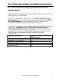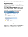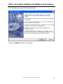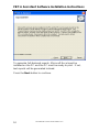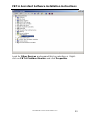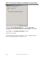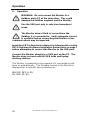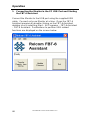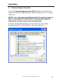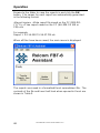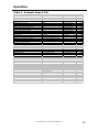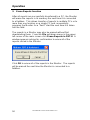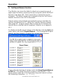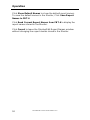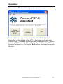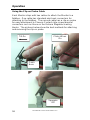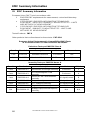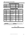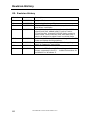
1
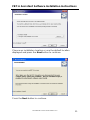
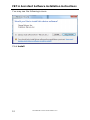
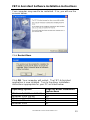
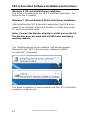
FBT-6-PA Fieldbus Monitor User Manual Relcom www.mtl-fieldbus.com 501-366 FBT-6-PA User Manual Rev G.0 1 © Copyright Relcom, Inc. 2011-2013 All rights reserved. No part of this manual may be reproduced, photocopied, stored on a retrieval system or transmitted without the express prior written consent of Relcom, Inc. Relcom, Inc. 2221 Yew St. Forest Grove, OR 97116 USA Tel: (503) 357-5607 Fax: (503) 357-0491 www.relcominc.com 2 501-366 FBT-6-PA User Manual Rev G.0 Table of Contents I. Table of Contents I. Table of Contents ................................................................. 3 II. Introduction ........................................................................... 5 III. Certifications ......................................................................... 6 IV. FBT-6 Assistant Software Installation Instructions ............... 7 Before Starting ......................................................................... 7 FBT-6 Assistant Installation ..................................................... 8 Windows 7 (32- and 64-bit) & 64-bit Vista Driver Installation 14 Windows Vista 32-bit Driver Installation................................. 15 Windows XP Driver Installation .............................................. 17 Windows 2000 Driver Installation ........................................... 21 Uninstalling the FBT-6 Assistant ............................................ 25 V. Operation ............................................................................ 26 Segment Check Mode ........................................................... 29 Manual Mode Functions ......................................................... 31 1. Voltage ....................................................................... 31 2. Peak Noise ................................................................ 32 3. Average Noise ........................................................... 34 4. Shield Short ............................................................... 36 5. Retransmit ................................................................. 37 6. Add-Drop ................................................................... 38 7. Device ........................................................................ 39 8. Low ............................................................................ 41 9. Device Count ............................................................. 42 10. Save Report ........................................................... 43 USB Port and Associated Features ....................................... 45 1. Connecting the Monitor to the PC USB Port and Starting the FBT-6 Assistant .............................................. 46 2. Transfer Reports function .......................................... 47 3. Erase Reports function .............................................. 50 4. Set Report Names function ....................................... 51 5. Set Alert Limits function ............................................. 53 6. Update Firmware function.......................................... 55 Using the Clip-on Probe Cable .............................................. 58 VI. Operation in Special Cases ................................................ 59 VII. Accessories ........................................................................ 62 VIII. Specifications ..................................................................... 63 IX. Service ................................................................................ 64 X. Warranty ............................................................................. 65 XI. EMC Summary Information ................................................ 66 XII. Revision History.................................................................. 68 501-366 FBT-6-PA User Manual Rev G.0 3 Table of Contents 4 501-366 FBT-6-PA User Manual Rev G.0 Introduction II. Introduction The FBT-6-PA Fieldbus Monitor is a Profibus PA physical segment and signal testing tool. It allows both engineering and service technicians to determine the health of fieldbus segments. The Monitor supports segment troubleshooting without interfering with segment operation. This manual was current at the time of printing. Go to www.relcominc.com for an electronic copy of the latest version of this manual. Further information on fieldbus is available in the Fieldbus Wiring Guide, also available on the website. Summary of Features The FBT-6-PA includes the following features: Tests the segment automatically and gives a OK/BAD indication without operator intervention. Measures segment DC voltage. Detects short circuits between the segment cable’s wires and shield. Indicates number of detected retransmissions to devices. Measures noise in three bands: Below, at and above fieldbus frequencies. Shows when a device is added to or dropped from the segment. Supports the transfer of data collected to a PC via a USB port. Supports firmware updates via a USB port. Displays the number of devices on the segment. Indicates the address of the device with the lowest detected signal level. Displays device addresses (in decimal and hexadecimal) signal levels and whether each device is a master or slave. Creates printable reports indicating segment condition. Usable in hazardous areas. 501-366 FBT-6-PA User Manual Rev G.0 5 Certifications III. Certifications CE The FBT-6-PA meets the European Union requirements for electromagnetic radiation by complying with the EMC Directive 89/336/EEC. FCC The FBT-6-PA is a Class A digital device and complies with Part 15 of the FCC Rules. Operation is subject to the following two conditions: (1) this device may not cause harmful interference, and (2) this device must accept any interference received, including interference that may cause undesired operation. Hazardous Area/Location Approvals FM US and Canada: Class I Division 2 Groups A,B,C, and D T4 Class I Zone 2 Group IIC T4 Class I Division 1 Groups A,B,C, and D T4 Class I Zone 0 and 1 Ex/AEx ia IIC T4 ATEX Ex ia IIC T4 ATEX Ex ic IIC T4 Gc 6 501-366 FBT-6-PA User Manual Rev G.0 FBT-6 Assistant Software Installation Instructions IV. FBT-6 Assistant Software Installation Instructions Before Starting FBT-6 Assistant software included with the Monitor supports the USB features of the Monitor. The FBT-6 Assistant software is on the FBT-6 Software and Documents CD included with the Monitor shipment. The FBT6-PA User Manual is also included on the CD and will be installed along with the FBT-6 Assistant software. You must be logged in as an administrator to install the software and driver. Install the FBT-6 Assistant Software before attaching the Monitor to the computer. The FBT-6 Assistant application should be installed first, followed by the USB driver. See the appropriate page below for driver installation instructions. Operating System Page for driver installation instructions Windows 7, 8 (32- and 64-bit) 14 Windows Vista (64-bit) 14 Windows Vista (32-bit) 15 Windows XP 17 Windows 2000 21 501-366 FBT-6-PA User Manual Rev G.0 7 FBT-6 Assistant Software Installation Instructions FBT-6 Assistant Installation The Monitor should not be attached yet. Close all Windows programs. You must be logged in as an administrator to install the software and driver. Insert the FBT-6 Software and Documents CD and the setup program will run automatically. If it does not run automatically, run the setup.exe file on the CD. You may see a screen similar to the one shown below: If you do see this screen, click Run setup.exe. You may also see a screen asking if you want to allow the FBT-6 Assistant software to make changes to the computer. Click Yes/Run/Continue as appropriate if you see this screen. 8 501-366 FBT-6-PA User Manual Rev G.0 FBT-6 Assistant Software Installation Instructions The following screen will be displayed: Press the Next button to continue. 501-366 FBT-6-PA User Manual Rev G.0 9 FBT-6 Assistant Software Installation Instructions To generate full-featured reports, Microsoft Excel must be installed on the PC and the PC must be ready to print. If not, text reports will be generated instead. Press the Next button to continue. 10 501-366 FBT-6-PA User Manual Rev G.0 FBT-6 Assistant Software Installation Instructions Choose an installation location or use the default location displayed and press the Next button to continue. Press the Next button to continue. 501-366 FBT-6-PA User Manual Rev G.0 11 FBT-6 Assistant Software Installation Instructions You may see the following screen: Click Install. 12 501-366 FBT-6-PA User Manual Rev G.0 FBT-6 Assistant Software Installation Instructions Your computer may need to be restarted. If so, you will see the screens below. Click Restart Now. Click OK. Your computer will restart. The FBT-6 Assistant application is now installed. Turn to the driver installation instructions appropriate for your PC as listed below: Operating System Windows 7, 8 (32- and 64-bit) Windows Vista (64-bit) Windows Vista (32-bit) Windows XP Windows 2000 Page for driver installation instructions 14 14 15 17 21 501-366 FBT-6-PA User Manual Rev G.0 13 FBT-6 Assistant Software Installation Instructions Windows 8 (32- and 64-bit) Driver Installation The driver is installed with the FBT-6 Assistant application. No further action is needed. Windows 7 (32- and 64-bit) & 64-bit Vista Driver Installation After installing the FBT-6 Assistant application, the USB driver needs to be installed. Attach the Monitor to a USB port on the PC with the provided cable. Note: Connect the Monitor directly to a USB port on the PC. The Monitor does not work with all USB hubs and laptop docking stations. The “Installing device driver software” text bubble appears followed by the “FBT-6 Device driver software installed successfully” text bubble. The driver installation is now complete and the FBT-6 Assistant program is ready for use. 14 501-366 FBT-6-PA User Manual Rev G.0 FBT-6 Assistant Software Installation Instructions Windows Vista 32-bit Driver Installation After installing the FBT-6 Assistant application, the USB driver needs to be installed. Attach the Monitor to a USB port on the PC with the provided cable. Note: Connect the Monitor directly to a USB port on the PC. The Monitor does not work with all USB hubs and laptop docking stations. The Found New Hardware window appears: Select Locate and install driver software (recommended). 501-366 FBT-6-PA User Manual Rev G.0 15 FBT-6 Assistant Software Installation Instructions Click Install this driver software anyway. This text bubble shows that the driver successfully installed. The Windows Vista driver installation is now complete and the FBT-6 Assistant program is ready for use. 16 501-366 FBT-6-PA User Manual Rev G.0 FBT-6 Assistant Software Installation Instructions Windows XP Driver Installation After installing the FBT-6 Assistant application, the USB driver needs to be installed. Attach the Monitor to a USB port on the PC with the provided cable. Note: Connect the Monitor directly to a USB port on the PC. The Monitor does not work with all USB hubs and laptop docking stations. The Found New Hardware Wizard window appears: Select No, not this time and press the Next button to continue. 501-366 FBT-6-PA User Manual Rev G.0 17 FBT-6 Assistant Software Installation Instructions Select the first option, Install the software automatically (Recommended), and press the Next button to continue. The computer searches for the driver. 18 501-366 FBT-6-PA User Manual Rev G.0 FBT-6 Assistant Software Installation Instructions Press Continue Anyway. 501-366 FBT-6-PA User Manual Rev G.0 19 FBT-6 Assistant Software Installation Instructions This dialog shows that the driver has been installed. Press the Finish button to exit. The Windows XP driver installation is now complete and the FBT-6 Assistant program is ready for use. Important note: The driver must be installed on each USB port that the Monitor will be connected to on the PC. The “Found New Hardware Wizard” will run for each new port that the Monitor is plugged into. Follow these driver installation instructions again for each additional USB port. 20 501-366 FBT-6-PA User Manual Rev G.0 FBT-6 Assistant Software Installation Instructions Windows 2000 Driver Installation After installing the FBT-6 Assistant application, the USB driver needs to be installed. Attach the Monitor to a USB port on the PC with the provided cable. Note: Connect the Monitor directly to a USB port on the PC. The Monitor does not work with all USB hubs and laptop docking stations. The following dialog box appears: The driver installs automatically after about 30 seconds. From the Start menu, open the Control Panel by selecting Start>Settings>Control Panel. Open System. 501-366 FBT-6-PA User Manual Rev G.0 21 FBT-6 Assistant Software Installation Instructions Select the Hardware tab. Click the Device Manager button. 22 501-366 FBT-6-PA User Manual Rev G.0 FBT-6 Assistant Software Installation Instructions Look for Other Devices and expand this by selecting +. Rightclick on FBT-6 Fieldbus Monitor and click Properties. 501-366 FBT-6-PA User Manual Rev G.0 23 FBT-6 Assistant Software Installation Instructions Select the Power Management tab. Uncheck Allow the computer to turn off this device to save power. Select OK. Select OK on the System Properties screen. Restart the computer. The Windows 2000 driver installation is now complete and the FBT-6 Assistant program is ready for use. 24 501-366 FBT-6-PA User Manual Rev G.0 FBT-6 Assistant Software Installation Instructions Uninstalling the FBT-6 Assistant To uninstall the FBT-6 Assistant use the Windows Add or Remove Programs feature in the Control Panel. In Vista use the Uninstall a program feature in the Control Panel. After the uninstall is complete, restart the computer. 501-366 FBT-6-PA User Manual Rev G.0 25 Operation V. Operation WARNING: Do not connect the Monitor to a fieldbus and a PC at the same time. This could damage the fieldbus segment and the Monitor. Use the USB port only in safe (non-hazardous) areas. The Monitor draws 10mA of current from the fieldbus it is connected to. Verify adequate current is available before connecting the Monitor or bus communications may be impacted. Install the FBT-6 Assistant software by following the section FBT-6 Assistant Software Installation Instructions on page 7 before attempting to connect the Monitor to the USB port. Connect the Monitor directly to a USB port on the PC. The Monitor does not work with all USB hubs and laptop docking stations. The Monitor is powered by the segment it is connected to and turns on automatically. The firmware version in the Monitor is displayed for 4 seconds upon powering up: RELCOM FBT-6-PA FW VER XX.XX 26 501-366 FBT-6-PA User Manual Rev G.0 Operation The Monitor begins measuring segment parameters. A bar (icon) twirls on the right side of the display’s second line while segment signals are present. If a bad frame is detected since the last display update then an underscore is displayed beneath the twirling icon. VOLTAGE 22.5V OK \ Twirling Icon Underscore Two buttons on the front of the Monitor control its operation. The buttons are labeled FUNC (for FUNCTION) and SEL (for SELECT). Press the FUNCTION button to cycle through the available Monitor functions. Some functions have multiple sub-screens of data available for display. Sub-screens available for each function are cycled through by pressing the SELECT button. Most functions are reset by holding down the SELECT button for 2 seconds. After holding down the SELECT button for 2 seconds, the data collected for that function is erased giving that function a “fresh start”. Holding down the SELECT and FUNCTION buttons at the same time for 2 seconds causes the Monitor to reset. The data collected by all Monitor functions is erased (unless saved using the SAVE REPORT feature). The reset is the same as if the Monitor was disconnected then re-connected to the segment. Short button presses (less than 2 seconds) are acted upon when the button is released, not when depressed. Figure 1 shows a block diagram of how to navigate through the Monitor functions. 501-366 FBT-6-PA User Manual Rev G.0 27 Operation Initial Screen and Segment Check Mode Voltage Peak Noise Fieldbus Frequency Peak Noise Low Frequency Peak Noise High Frequency Average Noise Fieldbus Frequency Average Noise Low Frequency Average Noise High Frequency Device X Device Y Device Z Device X Device Y Device Z Wiring (Shield Short Detect) Retransmit Add / Drop Device Low Device Count FUNC SEL Save Report Figure 1: Navigating through the Monitor’s Functions 28 501-366 FBT-6-PA User Manual Rev G.0 Operation Segment Check Mode When first attached to a segment, the Monitor enters the automatic Segment Check Mode and shows: SEGMENT CHECK IN PROGRESS The Monitor proceeds to automatically collect data and evaluates it to determine the health of the segment. Press either button to exit this mode and enter the Manual Mode at any time. In Segment Check Mode, the Monitor collects the same data that it collects in Manual Mode. As the data is collected, the Monitor evaluates the data to determine if it is out of specification. When the Monitor has collected enough data to determine that all of the measured parameters are in specification, the display shows: ALL MEASUREMENTS OK In this state the Monitor continues taking measurements and displays the OK message. If at any point in time the Monitor finds a parameter out of specification, it will jump into the Manual Mode and display the screen for the function associated with the first detected out of specification parameter. For example, if a (+) to Shield Short condition is detected, the Monitor enters the Shield Short function in Manual Mode and displays: (+) TO SHIELD SHORT The Monitor then operates in Manual Mode as described below from that point on. If low frequency noise present on the fieldbus is high enough in amplitude and frequency the noise is interpreted by the Monitor as a Fieldbus signal and causes the Monitor to get “stuck” in Segment Check Mode. In this case, troubleshoot and eliminate the source of the noise. 501-366 FBT-6-PA User Manual Rev G.0 29 Operation Parameters are evaluated against limits as OK or BAD. The limits can be set using the Set Alert Limits feature of the FBT-6 Assistant software. See the section Set Alert Limits function on page 53 for details. Table 1 lists the parameters checked in Segment Check Mode and the default limit values. Table 1: Parameters Checked in Segment Check Mode (Default Limit Values Shown) Voltage is >= 9VDC Peak noise is <= 75mV in the fieldbus band Peak noise is <= 150mV in the low and high frequency bands Average noise is <= 75mV in the fieldbus band Average noise is <= 150mV in the low and high frequency bands No shield short exists No retransmits No device drops or adds At least one device is detected on the segment The lowest device signal level is >= 150mV The lowest device signal level is <=1200mV 30 501-366 FBT-6-PA User Manual Rev G.0 Operation Manual Mode Functions Manual Mode is entered when the Monitor detects the first out of specification parameter or either button is pushed. The functions available are described below in the order in which they appear. 1. Voltage The DC voltage of the segment is displayed. VOLTAGE 22.5V OK If the DC voltage is less than the allowed limit (9V by default), BAD is displayed instead of OK. VOLTAGE 8.5V BAD The DC voltage limit is configurable using the Set Alert Limits function in the FBT-6 Assistant software. See Set Alert Limits function on page 53 for details. 501-366 FBT-6-PA User Manual Rev G.0 31 Operation 2. Peak Noise Peak noise is measured in three bands: frequencies in the fieldbus signaling band (Fieldbus Frequency, FF), frequencies below fieldbus signaling band (Low Frequency, LF), and frequencies above fieldbus signaling band (High Frequency, HF). The value displayed is the highest noise level measured since the last reset. The particular frequency band displayed is selected by pushing the SELECT button. The FF band is shown first followed by the LF then HF bands. PK FF NOISE 64 mV OK If the FF band noise level is above the allowed limit (75mV by default), the display will say BAD where it normally says OK. PK FF NOISE 99 mV BAD If the LF or HF band noise level is above the allowed limit (150mV by default), the display will say BAD where it normally says OK. PK LF NOISE 199 mV BAD The FF, LF, and HF noise level limits are configurable using the Set Alert Limits function in the FBT-6 Assistant software. See Set Alert Limits function on page 53 for details. Holding down the SELECT button for 2 seconds resets the selected peak noise value. 32 501-366 FBT-6-PA User Manual Rev G.0 Operation The approximate frequency bands monitored are listed below. Low Frequency Band Fieldbus Frequency Band High Frequency Band 50Hz to 4KHz 9KHz to 40KHz 90KHz to 350KHz 501-366 FBT-6-PA User Manual Rev G.0 33 Operation 3. Average Noise Average noise is measured in three bands: frequencies in the fieldbus signaling band (Fieldbus Frequency, FF), frequencies below fieldbus signaling band (Low Frequency, LF), and frequencies above fieldbus signaling band (High Frequency, HF). The value displayed is the average of the last 100 noise measurements. The particular frequency band displayed is selected by pushing the SELECT button. The FF band is shown first followed by the LF then HF bands. AVG FF NOISE 68mV OK If the FF band noise level is above the allowed limit (75mV by default), the display will say BAD where it normally says OK. AVG FF NOISE 1000mV BAD If the LF or HF band noise level is above the allowed limit (150mV by default), the display will say BAD where it normally says OK. AVG HF NOISE 200mV BAD The FF, LF, and HF noise level limits are configurable using the Set Alert Limits function in the FBT-6 Assistant software. See Set Alert Limits function on page 53 for details. Holding down the SELECT button for 2 seconds resets the selected average noise value. 34 501-366 FBT-6-PA User Manual Rev G.0 Operation The approximate frequency bands monitored are listed below. Low Frequency Band Fieldbus Frequency Band High Frequency Band 50Hz to 4KHz 9KHz to 40KHz 90KHz to 350KHz 501-366 FBT-6-PA User Manual Rev G.0 35 Operation 4. Shield Short If the segment wiring is good, the Monitor shows WIRING OK If one of the wires is shorted to the cable shield, the Monitor indicates a (+) or (-) to shield short as applicable. (+) TO SHIELD SHORT BAD The Monitor will always detect shorts of 4 Kohms or less. The amount of resistance the Monitor reports as a short varies with temperature and DC bus voltage and could be as high as 36 Kohms. Shorts come and go in some cases, such as with the presence of moisture or vibration. If the Monitor detected a short in the past then the short went away it indicates the short is intermittent. (+) TO SHIELD INTERMITTENT Holding the SELECT button down for 2 seconds resets the Shield Short function. Resetting the Shield Short function clears intermittent short indications. 36 501-366 FBT-6-PA User Manual Rev G.0 Operation 5. Retransmit If a device does not respond to a request or token frame, or if the Master does not hear the device’s response, the Master will query the device again. The Monitor displays the address of the device most recently requiring such a retransmission. RETRANSMIT NONE OK Or RETRANSMITS=3 DEVICE 19(13H) Press the SELECT button to cycle through a display for each device. The number of retransmissions (up to 250) detected since the Monitor was connected is displayed. If more than 250 retransmissions are detected for a device, 250+ is displayed. RETRANSMITS=250+ DEVICE 19(13H) Holding down the SELECT button for 2 seconds resets the number of retransmits for all devices to 0. 501-366 FBT-6-PA User Manual Rev G.0 37 Operation 6. Add-Drop If a new device is added to the segment, the Monitor detects it transmitting frames and will display its address and signal level. A device is considered dropped if a frame is retransmitted to the device. A Master device that is sent an FDL Status Request frame is also considered dropped. When a device is dropped by the Monitor and it will display the address and last known signal level of the dropped device. ADD or DROP NONE If a device drops from the segment the Monitor shows DROP 17 (11H) 690mV If a device is added to the segment, the Monitor shows ADD 19 (13H) 700mV The Monitor is more sensitive to device add and drop activity than control systems. The Monitor may momentarily indicate a device dropped from the fieldbus then quickly added back on while the device status provided by the control system is unchanged. Holding down the SELECT button for 2 seconds resets the Add-Drop function. Resetting the Add-Drop function also resets the Device and Device Count functions. 38 501-366 FBT-6-PA User Manual Rev G.0 Operation 7. Device For each device, the address (decimal and hexadecimal), signal level, and whether or not it is a Master or Slave is displayed in turn by pushing the SELECT button. If the signal level is at or above the minimum limit OK is displayed. The first device shown is a Master. “M” is displayed after the signal level to indicate that the device shown is a Master. “S” is shown for slaves. DEVICE 1000mV 16 (10H) M OK If the device was added after connecting the Monitor , a + symbol displays after the signal level. If the device was removed after connecting the Monitor, a - symbol is displayed after the last known signal level. DEVICE 41 (29H) 854mV + S OK The Monitor is more sensitive to device add and drop activity than control systems. The Monitor may momentarily indicate a device dropped from the fieldbus then quickly added back on while the control system shows no change. If the displayed device is dropped, has a signal level less than the allowed limit (150mV by default) or has a signal level more than the allowed limit (1200mV by default) the display will say BAD where it normally says OK. DEVICE 140mV 41 (29H) S BAD The minimum allowed signal level limit is configurable using the Set Alert Limits function in the FBT-6 Assistant software. See Set Alert Limits function on page 53 for details. 501-366 FBT-6-PA User Manual Rev G.0 39 Operation Holding down the SELECT button for 2 seconds will clear the “added” status of any devices added after connecting the Monitor (or since the last reset). Holding down the SELECT button for 2 seconds also deletes dropped devices from the Monitor’s internal device list. Resetting the Device function also resets the Add-Drop and Device Count functions. 40 501-366 FBT-6-PA User Manual Rev G.0 Operation 8. Low The Monitor displays the lowest (weakest) detected device signal level since the Monitor was connected and the address (decimal and hex) of the associated device. If the lowest signal level is at or above the minimum limit OK is displayed. LOW= 580mV OK ADDR= 41 (29H) If the lowest signal level is less than the allowed limit (150mV by default) or the lowest signal level is greater than the allowed limit (1200mV by default) the display will say BAD where OK is normally displayed. LOW= 149mV BAD ADDR= 41 (29H) The minimum and maximum allowed signal level limits are configurable using the Set Alert Limits function in the FBT-6 Assistant software. See Set Alert Limits function on page 53 for details. Holding down the SELECT button for 2 seconds resets the low signal level value. 501-366 FBT-6-PA User Manual Rev G.0 41 Operation 9. Device Count The Monitor displays the number of active devices on the segment. It also displays the number of devices present when the Monitor was first attached as the Initial Count. DEVICE COUNT 12 INITIAL CNT 12 If a device does not respond to a frame the Monitor considers the device to be dropped (no longer active). The device count is reduced by one. If a new device is added, the device count is increased by one. DEVICE COUNT 11 INITIAL CNT 12 The Monitor is more sensitive to device add and drop activity than control systems. The Monitor may momentarily indicate a device dropped from the fieldbus then quickly added back on while the control system showed no change. To make it easier to detect the adding or dropping of a device, the device count and initial count can be reset by holding down the SELECT button for 2 seconds. Resetting the Device Count function also resets the AddDrop and Device functions. 42 501-366 FBT-6-PA User Manual Rev G.0 Operation 10. Save Report The Monitor can save the data it collected as a report in one of eight numbered report locations (internal memory blocks). The display repeatedly cycles through three screens with each screen displayed for about three seconds. The first screen indicates the currently selected report name, report location number and the status of the report location: used or empty. The second and third screens describe how the SELECT button is used to save a report. Report 1 LOCATION 1 EMPTY HOLD DOWN SEL TO SAVE REPORT PUSH SEL TO PICK NEXT LOCATION The first screen displays LOCATION # EMPTY (# is the location number, 1 to 8) if no report is saved in the selected report location. The screen displays LOCATION # USED if a report is already saved in the selected report location. To save a report, first choose one of the eight report locations to store the report in. The Monitor starts at the first empty location. Momentarily pressing the SELECT button advances to the next report location. In the example below, Report 8 is the name of the report stored in location 8. Report 8 LOCATION 8 USED When the last report location, location 8, is displayed and the SELECT button is pressed, the display rolls back to the first report location, location 1. 501-366 FBT-6-PA User Manual Rev G.0 43 Operation To save a report in the selected report location, hold down the SELECT button for 2 seconds. The display shows, SAVING REPORT, while the report is saving . Report 5 SAVING REPORT When the report is saved, the display shows REPORT SAVED. Report 5 REPORT SAVED The next time this report location screen is displayed, the report status will indicate USED. Report 5 LOCATION 5 USED When a USED report location is chosen and the SELECT button is held down for 2 seconds the report is overwritten with a new report. Use the Set Report Names feature in the FBT-6 Assistant to change the report names. See the section Set Report Names function on page 51 for details. 44 501-366 FBT-6-PA User Manual Rev G.0 Operation USB Port and Associated Features The USB port on the Monitor can be connected to a PC. Using the FBT-6 Assistant program installed on a PC, reports collected on the Monitor can be transferred to an Excel file on the PC and the firmware in the Monitor can be updated. Install the FBT-6 Assistant software by following the instructions FBT-6 Assistant Software Installation Instructions on page 7 before attempting to connect the Monitor to the USB port. Connect the Monitor directly to a USB port on the PC. The Monitor does not work with all USB hubs and laptop docking stations. WARNING: Do not connect the Monitor to a fieldbus and a PC at the same time. This could damage the fieldbus segment and the Monitor. Only use the USB port in safe (non-hazardous) locations. 501-366 FBT-6-PA User Manual Rev G.0 45 Operation 1. Connecting the Monitor to the PC USB Port and Starting the FBT-6 Assistant Connect the Monitor to the USB port using the supplied USB cable. Connect only one Monitor at a time. Open the FBT-6 Assistant program by double clicking on the FBT-6 Assistant desktop icon or selecting Start – All Programs – FBT-6 Assistant – FBT-6 Assistant. Pushbuttons to perform USB related functions are displayed on the screen below. 46 501-366 FBT-6-PA User Manual Rev G.0 Operation 2. Transfer Reports function Click the Transfer Reports from FBT-6 button to transfer the reports saved in all eight Monitor report locations to a PC via the USB port. NOTE: Excel must be installed and the PC must be ready to print to generate full-featured Excel spreadsheet reports. Otherwise, text file reports will be generated. The FBT-6 Assistant displays a screen like the one below allowing selection of the folder to save the reports in. 501-366 FBT-6-PA User Manual Rev G.0 47 Operation Browse to the folder to save the reports in and click the OK button. File names for each report are automatically generated in the following format: <Report name> <Date report file saved on the PC (MM-DDYYYY)> <Time report saved on the PC (HH-MM-SS AM or PM)>.xls For example Report 1 02-14-2007 3-59-37 PM.xls When all files have been saved, the main menu is displayed. The reports are saved in a formatted Excel spreadsheet file. The contents of the file and how it will look when opened in Excel are shown in Table 2. 48 501-366 FBT-6-PA User Manual Rev G.0 Operation Table 2: Example Report File Report 1 Segment Measurements Data Acceptable Values OK/BAD Voltage Lowest Device Signal Lowest Device Signal Address Avg Fieldbus Frequency Noise Peak Fieldbus Frequency Noise Avg Low Frequency Noise Peak Low Frequency Noise Avg High Frequency Noise Peak High Frequency Noise Shield Short LAS Address Most Recent Add/Drop Address Device Add or Drop Date/Time of Device Add/Drop Number of Active Devices 21.8V 725mV 16 (10H) 0mV 4mV 5mV 5mV 1mV 32mV No Shorts 16 (10H) No Devices Added/Dropped None Added/Dropped Not Available 1 9.0V Minimum 150mV Minimum OK OK 75mV Maximum 75mV Maximum 150mV Maximum 150mV Maximum 150mV Maximum 150mV Maximum No Shorts OK OK OK OK OK OK OK None Added/Dropped OK Device Measurements Data Acceptable Values OK/BAD Device Address Signal Level Added/Dropped Retransmits 16 (10H) 729mV Not Added/Dropped 0 150mV Minimum Not Added/Dropped 0 OK OK OK Measurement Summary: All Measurements are OK Data collected by _______________________________________________ Report approved by _______________________________________________ 501-366 FBT-6-PA User Manual Rev G.0 49 Operation 3. Erase Reports function After all reports are successfully transferred to a PC, the Monitor will erase the reports in its memory the next time it is connected to a fieldbus. This allows transfer of reports to multiple PCs or to more than one location on a single PC and conveniently prepares the Monitor for a “fresh” start the next time it is taken into the field. The reports in a Monitor may also be erased without first downloading them. From the File pull-down menu in the upper left corner of the main screen click Erase Reports in FBT-6. A window appears asking for confirmation to erase all of the reports stored in the Monitor. Click OK to erase all of the reports in the Monitor. The reports will be erased the next time the Monitor is connected to a fieldbus. 50 501-366 FBT-6-PA User Manual Rev G.0 Operation 4. Set Report Names function The Monitor can save the data it collects as a report in one of eight report locations (memory blocks) using the SAVE REPORT function (see page 43). Each report has a name that can be changed. The report names are changed using the Set Report Names function in the FBT-6 Assistant. Report names automatically generate file names and titles for reports transferred to a PC using the Transfer Reports feature (see page 47). Report names help to keep track of where the reports were collected (which segment, location on a segment, etc.). To display and edit report names in the Monitor click the Set pulldown menu and select Report Names. The Display/Edit Report Names window appears showing the current report names. Type in the desired report names and click Save Report Names to FBT-6. This writes the report names to the Monitor. The report names must be 1-15 characters long and cannot contain the following characters: \ / : * ? < > | 501-366 FBT-6-PA User Manual Rev G.0 51 Operation Click Show Default Names to show the default report names. To save the default names in the Monitor, Click Save Report Names to FBT-6. Click Read Current Report Names from FBT-6 to display the report names stored in the Monitor. Click Cancel to leave the Display/Edit Report Names window without changing the report names stored in the Monitor. 52 501-366 FBT-6-PA User Manual Rev G.0 Operation 5. Set Alert Limits function The Monitor evaluates some of the parameters it monitors as OK or BAD based upon user configurable limits. To display and edit these limits click the Set pull-down menu and select Alert Limits. Type in the desired limits for each parameter and click Save Limits to FBT-6 to write the limits to the Monitor. 501-366 FBT-6-PA User Manual Rev G.0 53 Operation Click Show Default Limits to show the factory default limit values. To save the default limits in the Monitor, Click Save Limits to FBT-6. The default limits are based upon the Foundation Fieldbus physical layer standard (IEC 61158) where possible. Click Read Limits from FBT-6 to display the limit values stored in the Monitor. Click Cancel to leave the Set Alert Limits window without changing the limits stored in the Monitor. 54 501-366 FBT-6-PA User Manual Rev G.0 Operation 6. Update Firmware function New features for the Monitor may be released occasionally. These features may be added to Monitor units already in the field by updating the Monitor firmware. The Update Firmware function allows the existing firmware in the Monitor to be replaced with new firmware. Download the Monitor firmware file from www.relcominc.com and save it on the PC. Start the FBT-6 Assistant and click the Update Firmware button to begin the update process. The Choose Hex File window opens. 501-366 FBT-6-PA User Manual Rev G.0 55 Operation Specify the new firmware file by browsing to the folder containing the firmware file, selecting the file, then clicking the Open button. The Final Check! window opens as shown below. Updating the firmware erases any reports saved in the Monitor. Click OK to proceed with the update. Click Cancel to stop the update and return to the main FBT-6 Assistant screen. 56 501-366 FBT-6-PA User Manual Rev G.0 Operation After clicking OK, the following screen appears. Once the firmware update is complete, the FBT-6 Assistant status line in the middle of the FBT-6 Assistant main menu will change from, “Firmware update will take a few moments. Please wait…” to “FBT-6 firmware loaded. Ready...”. Close the FBT-6 Assistant program by clicking the Exit button and begin using the Monitor. 501-366 FBT-6-PA User Manual Rev G.0 57 Operation Using the Clip-on Probe Cable Each Monitor ships with two cables to attach the Monitor to a fieldbus. One cable has standard mini-hook connectors for attaching to the fieldbus. The second cable has a clip-on probe for easy attachment to Phoenix Contact style screw terminal connectors such as those on the Relcom Megablock wiring blocks. The pictures below show the best methods for attaching and removing the clip-on probe. Tilt On Clicks When On Catch Here Squeeze Off 58 501-366 FBT-6-PA User Manual Rev G.0 Operation in Special Cases VI. Operation in Special Cases The Monitor operates differently under certain special circumstances. This section describes the behavior of the Monitor in these special cases. Limitations The Monitor will transfer report data to the PC on a total of up to 32 devices per segment including the Master (each device has a separate address). The Not Added/Dropped devices are transferred first, followed by Added devices, and finally Dropped nd devices. The data for devices beyond the 32 device is not transferred to the PC. Silent Segment Behavior The fieldbus segment that the Monitor is connected to may contain no frame traffic for long periods of time. This Silent Segment condition may be present when the Monitor is initially connected to the segment or may occur after the segment has been transmitting frames for some period of time. The Monitor will continue to record and display data, even when the segment is silent. When the segment is in a silent condition the Monitor will collect a set of non-device related data (DC Volts, Noise, etc.). In addition, if the segment remains silent for about 2 seconds, the Monitor will mark all devices as dropped and set the (active) device count to 0. 501-366 FBT-6-PA User Manual Rev G.0 59 Operation in Special Cases Excess Noise Mode High levels of noise on the fieldbus can make fieldbus signals undetectable. In addition, the noise may be interpreted as constantly transmitted corrupted fieldbus data. In this case, the Monitor becomes unresponsive because it is spending so much time trying to identify good fieldbus frames. When this situation occurs, the Monitor recognizes that it is spending too much time trying to identify good fieldbus frames and will enter Excess Noise Mode. Upon entering Excess Noise Mode, the Monitor quits looking for fieldbus transmissions and the following display appears: EXCESS NOISE, NO FIELDBUS MEAS. * Pressing either the FUNCTION or SELECT button returns to the Voltage screen and the screens can be navigated normally. However, only fieldbus physical layer information (voltage, noise, and shield shorts) is displayed. Information contained in fieldbus data (device addresses, signal level, number of devices, etc.) is not available and the data portion of the screens normally displaying fieldbus data is blank. The twirling icon is also replaced by “*”. To exit the Excess Noise Mode, remove the source of the noise from the bus then reset the Monitor by holding down both buttons for 2 seconds or disconnecting and reconnecting the Monitor. If the high noise level is still present, the Monitor will again enter Excess Noise Mode. Note that in Excess Noise Mode, the Monitor cannot differentiate between fieldbus signals and noise. As a result, the Monitor measures noise plus signal when it displays noise values. The noise level measurements displayed will be very high. 60 501-366 FBT-6-PA User Manual Rev G.0 Operation in Special Cases Unavailable Data The data for some or all displays will be unavailable during Initial Discovery, Excess Noise Mode, after a function is reset, or because the segment is silent. When the Monitor is collecting and processing segment data, information may not be ready for display. In this case, only the selected Monitor function name is displayed. The FUNCTION and SELECT buttons still navigate through the menus as they normally would. 501-366 FBT-6-PA User Manual Rev G.0 61 Accessories VII. Accessories Part Number FBT-A61 Description FBT-A62 FBT-6 USB Cable FBT-A63 FBT-6 Fieldbus Cable with Clipon Probe FBT-A64 Clip-on Probe Picture FBT-6 Fieldbus Cable with MiniHook Probes Contact your local MTL representative for pricing and availability. www.mtl-fieldbus.com (or in the U.S. call 1-888-746-4685) 62 501-366 FBT-6-PA User Manual Rev G.0 Specifications VIII. Specifications Input Voltage: Fieldbus Mode: 8 to 32 VDC USB Mode: 4.1 to 5.5 VDC Max. Input Current: Fieldbus Mode: 10 mA USB Mode: 30 mA Power Dissipation: Fieldbus Mode: 320 mW max (@ 32 VDC) USB Mode: 165 mW max (@ 5.5 VDC) Operating Temperature: –20 to +50°C * Dimensions: 146 x 88 x 28 mm (5.7 x 3.5 x 1.1in.) Weight: 378g (0.83lb.) Case material: ABS DC Voltage Measurement Range: 8 to 32 VDC +/- 0.5 VDC LF Noise Measurement Range: 50Hz to 4KHz 0 to 1000 mVpp ±15% ±25mVpp FF Noise Measurement Range: 9KHz to 40KHz 0 to 1000 mVpp ±10% ±25mVpp HF Noise Measurement Range: 90KHz to 350KHz 0 to 250 mVpp ±20% ±25mVpp Signal Level Measurement Range: 0.12 to 2 Vpp ±10% ±0.025Vpp * Display updates very slowly below –10°C. The Monitor is powered by the Fieldbus and draws approximately 9.4 mA of current from the segment (depending on bus voltage and ambient temperature). Specifications subject to change without notice. 501-366 FBT-6-PA User Manual Rev G.0 63 Service IX. Service The Monitor does not contain any user serviceable parts. All adjustments and/or repairs have to be performed at the factory. If the Monitor needs to be serviced, return it to Relcom, Inc. If the Monitor is covered by the limited warranty, the repairs or replacement will be made free of charge. For service outside the warranty, please call or write to determine the charges for the service before sending the Monitor. 64 501-366 FBT-6-PA User Manual Rev G.0 Warranty X. Warranty Relcom, Inc. warrants the Monitor to perform as described in this manual under normal use for a period of one year after delivery to the original purchaser. This warranty does not apply if the Monitor has been disassembled, modified or used for purposes other than those described in this manual. Upon verification of any defect, Relcom, Inc. shall, at its option, repair or replace the defective unit. In no event does Relcom, Inc. assume liability for incidental or consequential damages. This warranty is the extent of the obligation or liability assumed by Relcom, Inc., and no other warranty or guarantee is either expressed or implied. Relcom, Inc. reserves the right to make design changes to the Monitor without notice and with no obligation to make the same or similar changes to units previously manufactured. Relcom, Inc. has made every effort to assure the accuracy of the information contained in this manual. Relcom is not, however, responsible for any errors or omissions. Please contact us with any questions or suggestions. Relcom, Inc. 2221 Yew St. Forest Grove, OR 97116 USA Tel: (503) 357-5607 Fax: (503) 357-0491 Email: [email protected] www.relcominc.com 501-366 FBT-6-PA User Manual Rev G.0 65 EMC Summary Information XI. EMC Summary Information European Union EMC Tests in accordance with: EN61326 EMC requirements for measurement, control and laboratory equipment CISPR22:2005 (EN55022) INFORMATION TECHNOLOGY EQUIPMENT - RADIO DISTURBANCE CHARACTERISTICS - LIMITS AND METHODS OF MEASUREMENT CISPR24:2002 (EN55024) INFORMATION TECHNOLOGY EQUIPMENT - IMMUNITY CHARACTERISTICS - LIMITS AND METHODS OF MEASUREMENT Tested Products: FBT-6 Other products that conform based on these tests: FBT-6-PA European Union Electromagnetic Compatibility (EMC) Tests in accordance with EC Council Directive 89/336/EEC Emissions Tests per EN61326 Class A Result Standard Description Port Comments Pass EN61326 Radiated Emissions Enclosure N/A N/A EN61326 Conducted Emissions AC Power N/A Immunity Tests per EN61326 Annex A Result Standard Description Port Criteria Pass EN61000-4-2 Electrostatic Discharge Immunity Enclosure C Pass EN61000-4-3 RF Electromagnetic Field Immunity Enclosure A Pass EN61000-4-4 Electrical Fast Transient/Burst Immunity I/O signal/control B Pass EN61000-4-5 Surge Immunity I/O signal/control B Pass EN61000-4-6 RF Conducted Immunity I/O signal/control A N/A EN61000-4-8 Magnetic Field Immunity N/A N/A N/A EN61000-4-11 Voltage Dips/Short Interruptions Immunity N/A N/A 66 501-366 FBT-6-PA User Manual Rev G.0 EMC Summary Information Emissions Tests per EN55022 Class B Result Standard Description Port Comments Pass EN55022 Radiated Emissions Enclosure N/A Pass EN55022 Conducted Emissions AC Power N/A Immunity Tests per EN55024 Result Standard Description Port Criteria Pass EN61000-4-2 Electrostatic Discharge Immunity Enclosure B Pass EN61000-4-3 RF Electromagnetic Field Immunity Enclosure A Pass EN61000-4-4 Electrical Fast Transient/Burst Immunity AC Mains B Pass EN61000-4-5 Surge Immunity AC Mains B Pass EN61000-4-6 RF Conducted Immunity AC Mains A N/A EN61000-4-8 Magnetic Field Immunity N/A N/A N/A Voltage Dips/Short EN61000-4-11 Interruptions Immunity N/A N/A I, Cyrus Kelly , representative for Relcom, Inc., verify that the product tested is representative of production products to be sold. Based on the results presented in this report the FBT-6 product family can be marked with the FCC mark (as a Class A digital device) and the CE mark. (signature) 501-366 FBT-6-PA User Manual Rev G.0 67 Revision History XII. Revision History Revision Date Description A 11/27/2006 Original Release B 04/17/2007 Updated with release 2 features C 01/07/2008 D.0 01/07/2009 E.0 04/17/2009 E.1 12/7/2009 F.0 5/27/2011 Added ATEX Cat. 3 certifications, updated software and driver installation. Added Vista installation instructions, added 1200mV signal level limit, added Initial Count to Device Count function, changed OK/BAD limits screen to Alert Limits, Device function now indicates BAD if device is dropped or signal level is outside limits. Added notes about Monitor not working with all USB hubs and laptop docking stations. Added note about possibility of Monitor getting stuck in Segment Check Mode. Added Windows 7 installation instructions. G.0 4/10/2013 68 Removed ATEX Ex nL IIC T4 marking as “nL” is no longer supported in the EU. . Added instructions for installation on Windows 8. 501-366 FBT-6-PA User Manual Rev G.0 NOTES 501-366 FBT-6-PA User Manual Rev G.0 69 NOTES 70 501-366 FBT-6-PA User Manual Rev G.0 Navigating through the Monitor’s Functions 501-366 FBT-6-PA User Manual Rev G.0 71 Relcom, Inc. 2221 Yew St. Forest Grove, OR 97116 USA Tel: (503) 357-5607 Fax: (503) 357-0491 www.relcominc.com 72 501-366 FBT-6-PA User Manual Rev G.0