1
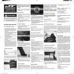
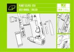
™
This is not a toy. Misuse may cause serious injury or death.
Eye protection designed specifically for paintball must be
worn by the user and persons within range. Recommend 18
years of age or older to purchase. Persons under 18 years
of age must have adult supervision.
BT-16
H I GH P E RF OR M A NC E P A I N TB A L L M AR K ER
U SER M A NU A L : T A CT I C A L / EL I T E / F I E LD
3 3 0 5 E . W A SH I N G T ON B OU L EV A RD
F ORT W A YN E, I N D I A N A 4 6 8 0 3
ww w. b tp ai nt b a ll. c om
READ OWNER’S MANUAL BEFORE USING.
Rules of Safe Marker Handling
1. Treat every marker as if it were loaded.
2. Never look down the barrel of a paintball marker.
3. Keep your finger off the trigger until ready to shoot.
4. Never point the marker at anything you don’t wish to shoot.
5. Keep the marker on safe until ready to shoot.
6. Keep the barrel blocking device in/on the marker’s muzzle when not shooting.
7. Always remove paintballs and propellant source before disassembly.
8. After removing propellant source, point marker in safe direction and discharge
until marker is degassed.
9. Store the marker unloaded and de-gassed in a secure place.
10. Follow warnings listed on propellant source for handling and storage.
11. Do not shoot at fragile objects such as windows.
12. Every person within range must wear eye, face and ear protection designed
specifically to stop paintballs and meeting ASTM standard F1776.
13. Always measure your marker’s velocity before playing paintball and never shoot at
velocities in excess of 91.44 meters (300 feet) per second.
BT Paintball Designs, Inc.
Model BT-16
No part of this document may be copied or reproduced without the prior written
consent of BT Paintball Designs, Inc.
Congratulations on your selection of the BT-16 paintball marker. The BT-16 is
made to provide you with many years of reliable performance. BT Paintball
Designs, Inc. is honored that you have chosen the BT-16 as your marker of
choice and hope you enjoy using this high quality product.
BT-16 Specifications
Model.................................................................................................................BT-16
Caliber................................................................................................................. .68
Action................ ..................................................................................Semi-Automatic
Powered............... .........................................................CO2,Compressed Air or Nitrogen
Cycle Rate................ .............................................................................................13BPS
Main Body Material....................................................................................Billet Aluminum
Accuracy Range.......................................................................................................150+ft
The BT-16 comes with a removable barrel system. This feature allows the user
to select a barrel that is most suitable for the playing conditions. Standard barrels are mirror-honed with a step-bore and porting and stock length is 8 inches.
1
NOTE: Eye protective devices designed specifically for paintball
use must be worn by the operator and anyone within range.
Air Cylinder Installation
1. To install loader check vertical feed adapter
and loader to make sure they are free from
debris and obstructions.
2. Place the feed neck of the loader into the
adapter all the way in until it stops.
3. Align the loader so that the lid is in the rear and
the loader is parallel with the marker.
4. Twist the locking ring of the feed adapter clockwise until it is snug.
5. You are now ready to load the marker with
paintballs.
Read this entire manual before loading, attaching a propellant source or in any way
attempting to operate the BT-16.
Barrel Installation
1. While pointing the marker in a safe direction,
make sure that it is degassed, with hopper
removed, no paintballs are in the feed port or
the breech and the safety is set to “safe”.
2. Place the threaded end of the barrel into the
front opening of the marker body.
3. Turn the barrel clockwise into the marker, until
it stops (do not over tighten).
4. Adjust the barrel accessories if necessary.
5. Install a barrel blocking device. This can be a
barrel plug or other such device that prevents
the accidental discharge of a paintball.
Air Cylinder Installation
1. Make sure the barrel blocking device is properly installed and the marker safety is set to “safe”.
2. While pointing the marker in a safe direction, cock the marker by pulling the T-handle located
on the top rear of the marker all the way back until it stops.
3. Release the T-handle and allow it to slide all the way forward.
4. The marker is now cocked.
5. Locate the air cylinder adapter. The BT-16 Elite cylinder adapter is located at the base of the
pistol grip. Other models have the air cylinder adapter located below the center of the marker
and just in front of the trigger guard.
6. Turn the marker so that the air cylinder adapter is pointed upwards while keeping the muzzle
of the marker pointed in a safe direction
7. Insert the threaded cylinder valve end into the adapter.
8. Without pushing the cylinder, twist the cylinder clockwise and allow the threads to draw the
cylinder into the marker, until it stops. Your marker is now charged.
Loader Installation
Velocity Adjustment
1. Always check the velocity of the marker prior to playing paintball. Different playing fields may
have different maximum velocity limits. At no time should you shoot at velocities above 300
feet per second.
2. Put on an eye protective device designed specifically for paintball and make sure that anyone
within range of the marker does the same.
3. While pointing the marker a safe direction, remove the barrel blocking device.
4. Point the marker over a chronograph that will measure the velocity of the paintballs discharged
by the marker.
5. Set the trigger safety to “fire”.
6. Pull the trigger and check the reading on the chronograph.
7. Locate the velocity adjuster screw on the center of marker opposite the name plate.
8. Using a 5/32 hex key, turn the screw Inward or clockwise to reduce the velocity, and outward
or counterclockwise to increase the velocity of the paintballs discharged from the marker.
DO NOT REMOVE THE VELOCITY
ADJUSTMENT SCREW.
2
BT-16 FIELD MARKER
Parts List
BT-16 TACTICAL & ELITE MARKER
Parts List
1
Barrel
22
Valve Spacer
2
Barrel O-ring
23
Rear Valve Seal
3
Barrel Adapter
24
Valve Tube
4
Barrel Adapter Screw
25
Connecting Rod
5
Ball Retainer
26
Rear Valve O-rings
6
Receiver
27
Hammer
7
Bottom Plate
28
T-Handle/Hammer Connector
8
Bottom Plate Screws
29
Top Rail Screw
9
Cylinder Adapter
30
Top Rail
10
Cylinder Adapter Screw
31
Vertical Feed Adapter
11
Cylinder Adapter Screw Interface
32
T-Handle
12
Bolt O-ring
33
T-Handle Spring
13
Bolt
34
T-Handle Spring Retainer
14
Velocity Adjuster Screw
35
Spacer Block
15
Valve Body
36
Trigger Frame Assembly
16
Valve O-ring
37
Trigger Frame Retaining Pins
17
Valve Washer
38
Receiver Bushing
18
Valve Spring
39
Mainspring
19
Valve Cup
40
Mainspring Guide
20
Valve Seal
41
Rear Cap O-Ring
21
Valve Pin
42
Rear Cap
28
25
23
30
31
15
18
21
19
22
Valve Spacer
43
Vertical Foregrip Insert
64
Hand Guard Spring
Barrel O-ring
23
Rear Valve Seal
44
Vertical Foregrip O-ring
65
Hand Guard Rear Collar
3
Barrel Adapter
24
Valve Tube
45
Vertical Foregrip Housing
66
Hand Guard Spacer
4
Barrel Adapter Screw
25
Connecting Rod
46
Collapsible Stock
67
Hand Guard Pin
5
Ball Retainer
26
Rear Valve O-rings
47
Collapsible Stock Shaft
68
Hand Guard Set
6
Receiver
27
Hammer
48
Collapsible Stock Retainer
69
Hand Guard Front Collar
7
Bottom Plate
28
T-Handle/Hammer Connector
49
Collapsible Stock Bushing
70
Front Sight Pin Assembly
8
Bottom Plate Screws
29
Top Rail Screw
50
Collapsible Stock O-ring
71
Front Sight Body
9
Cylinder Adapter
30
Top Rail
51
Carrying Handle Lugs
72
Front Sight Retainer Set
10
Cylinder Adapter Screw
31
Vertical Feed Adapter
52
Peep Sight Bushing
11
Cylinder Adapter Screw Interface
32
T-Handle
53
Carrying Handle Retainer
12
Bolt O-ring
33
T-Handle Spring
54
Carrying Handle
13
Bolt
34
T-Handle Spring Retainer
55
Carrying Handle Screws
14
Velocity Adjuster Screw
35
Spacer Block
56
Peep Sight Axle
15
Valve Body
36
Trigger Frame Assembly
57
Peep Sight Clip
16
Valve O-ring
37
Trigger Frame Retaining Pins
58
Peep Sight
17
Valve Washer
38
Receiver Bushing
59
Peep Sight Wheel
18
Valve Spring
39
Mainspring
60
Peep Sight Wheel Screw
19
Valve Cup
40
Mainspring Guide
61
Peep Sight Wheel Spring Pin
20
Valve Seal
41
Rear Cap O-Ring
62
Peep Sight Retaining Screws
21
Valve Pin
42
Rear Cap
63
Snap Ring
28
29
33
22
30
42
32
16
40
41
38
5
2
6
3
23
19
12
34
39
39
36
64
52
55
54
37
9
7
8
44
51
40
43
67
46
41
65
69
56
32
33
4
37
61
10
63
70
7
18
26
5
66
11
9
29
59 58
57
53
1
4
1
21
12
36
10
27
35
13
2
39
3
15
14
34
6
20
31
12
60
25
24
17
35
13
Barrel
2
26
22
20
16
27
1
45
47
71
49
8
68
50
48
72
3
Proper storage of the marker
When you are finished using the marker it is important that you properly store it. This
will not only serve to increase the life of the marker and result in reduced maintenance
requirements, it will be in keeping with important safety procedures.
Unloading
1. Put on an eye protective device designed specifically for paintball and make sure that anyone
within range of the marker does the same.
2. Make sure the barrel blocking device is properly installed and the marker safety is set to “safe”.
3. Loosen the loader locking nut.
4. While holding the paintball hopper in place, invert the marker so that the hopper is below the
marker.
5. Remove the hopper and all paintballs.
6. While pointing the marker in a safe direction, remove the barrel blocking device and set the
safety to “fire”.
7. Keep the marker pointed in a safe direction and pull the trigger several time to insure there are
no balls remaining in the chamber or the barrel.
8. Properly re-install the barrel blocking device and set the safety on “safe”.
Removing The Air Supply
1. Make sure the barrel blocking device is properly installed and the marker safety is set to “safe”.
2. Point the marker in a safe direction and turn the cylinder counter clockwise or out _ of a turn.
This allows the cylinder valve to close without damaging the cylinder O-ring.
3. While pointing the marker in a safe direction, disengage the safety (set to “fire”).
4. Keeping the marker pointed in a safe direction, pull the trigger until the remaining CO2 or air is
expelled and it fails to re-cock.
5. Unscrew the cylinder from the marker.
6. The marker is now ready to be cleaned or put a way for future use.
Cleaning the marker
Once the marker is unloaded and the air cylinder is removed you can use a damp cloth to wipe
off paint, oil, dirt, and debris. You can also use warm water to rinse the marker clean. Once your
marker is clean and dry you can re-oil it using a light premium marker oil such as Hoppes #9 marker oil. To oil the marker put a few drops on the front bolt, rear bolt, linkage arm, trigger and sear.
To access the rear bolt and linkage arm you must remove the top plate (see marker disassembly
section).
Disassembly and field stripping
(MARKER MUST BE UNLOADED, DEGASSED AND UNCOCKED BEFORE ANY
DISASSEMBLY)
Remove The Barrel
Unscrew the barrel from the marker by turning the barrel counterclockwise until it is
removed from the marker.
Trigger Frame Removal/Pivot
The trigger frame may be removed or may be pivoted out of the way without removing.
To pivot the trigger frame, remove the rear trigger frame retention pin and tilt downward
while leaving the front pin in place.
1. To remove the trigger frame, remove both retention pins and pull the trigger frame down and
away from the receiver.
Always store the marker in a secure location when not in use so as
to prevent access by unauthorized persons.
4
Removal of Cylinder Adapter
Removal of T-handle, Bolt Rod and Rear Bolt
NOTE: Air source must be removed for this procedure
1. Using a flathead screw driver, turn the
cylinder adapter screws counterclockwise
and remove them.
2. The cylinder adapter will pull directly out
of the marker and valve assembly.
1. Remove the T-handle spring retainer which is located at the top center of the marker.
2. Pull the T-handle back and up to remove it from the rear bolt.
3. Turn the marker upside down and remove the bolt rod(you may have to shake the marker to
get the rod to fall out).
4. Pull the rear bolt out of the back of the receiver.
Removal of Valve, Valve Tube, and Front Bolt
1. Screw the velocity screw all the way in.
2. Pull the valve, valve tube, and front bolt out of the back of the marker.
Top Plate Removal
(If marker is equipped with a carrying handle it must first be removed by loosening the
carrying handle screws)
1. Using a 5/64 hex key wrench remove the top plate screw.
2. Pull the top plate and the T-handle simultaneously towards the rear of the marker and lift off
until top plate can be lifted off the marker.
Removal of Barrel Adapter
and Ball Retainer
Removal of Rear Cap or Rear Stock
NOTE: The trigger frame must first be removed or pivoted downward before starting this procedure.
Turn the rear cap or stock counterclockwise until the cap or stock is completely
removed. This procedure will also allow you to remove the drive spring, drive spring pin,
and bolt buffer.
1. Using a 5/64 hex key, remove the bottom
plate screws.
2. Pull the bottom plate directly off the bottom
of the marker.
3. Using a flathead screwdriver remove the ball
retainer (large brass fitting).
4. Loosen the barrel adapter screw located in
front of the ball retainer with a 5/64 hex key
by turning it counterclockwise at least 2
turns.
5. Pull the barrel adapter out of the front of the
marker.
P11 arrows indicate ball retainer and barrel
adapter screw.
There is no need for further
disassembly of the marker.
5
Reassembly
To reassemble the marker reverse the Disassembly instructions starting with the valve,
valve tube, and front bolt. While reassembling the marker you should oil all O-rings and
sliding parts. All parts and O-rings returned to the marker should be free of debris and
visual nicks and scratches which can alter the performance of the marker. All screws
returned to the marker must be tightened so there is no chance of them vibrating loose.
Storage and Transportation
1. BT-16 must be clear of all paint and propellant when not being used.
2. Be sure to have marker in SAFE MODE when not in use.
3. Make sure barrel blocking device is in place.
4. Store BT-16 and propellants in a cool dry place.
BT PAINTBALL DESIGNS, INC.
LIMITED WARRANTY
BT PAINTBALL DESIGNS, INC. warrants the replacement of any original part due to
defect in materials and/or workmanship of this marker. This warranty will be in effect for
twelve (12) months for parts and twelve (12) months for labor following the original date
of purchase for the original purchaser. Such warranty service will be provided only if the
warranty registration card included with this manual is filled in completely and on file at
BT PAINTBALL DESIGNS, INC. All other service will be duly charged for and returned
via UPS C.O.D.
BT PAINTBALL DESIGNS, INC. will replace without charge any original part that is
determined by BT PAINTBALL DESIGNS, INC. to be defective under the terms of this
warranty. However, shipping charges are not covered hereunder. Failure due to an
accident, abuse, neglect, modification, normal wear, operator error, maintenance by
other than an authorized BT PAINTBALL DESIGNS, INC. dealer, or use of parts
inconsistent with the use originally intended for the marker as sold, is not covered by
this warranty.
There are no other warranties or guarantees, expressed or implied, made by BT PAINTBALL DESIGNS, INC. on this marker. The sole and exclusive liability of BT PAINTBALL
DESIGNS, INC. and/or its authorized dealers, affiliates, or agents pursuant to this warranty will be for repair or replacement of the defective part; incidental or consequential
damages are expressly excluded hereunder.
5. Keep the BT-16 secure location.
6. Your BT-16 must be free of all paint and not attached to an propellant source
while being transported to and from the playing field.
7. Observe and obey all local, state and federal laws concerning the transportation of paintball markers. For information concerning any of the laws in
your area, contact your local law enforcement.
BT PAINTBALL DESIGNS, INC., its authorized dealers, affiliates, or agents, will not be
liable under this warranty, nor under any state or federal law, or the common law or otherwise for any damage or failure, including personal injury, resulting from such use
and/or alteration. This warranty gives you specific legal rights, and you may also have
other rights that may vary from state to state.
For warranty parts, service or information contact:
BT PAINTBALL DESIGNS, INC.
3305 EAST WASHINGTON BLVD.
FORT WAYNE, INDIANA 46803
260-424-9100
[email protected]
6
NOTES:
7