1
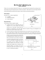
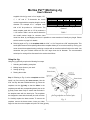
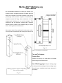
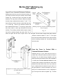
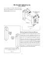
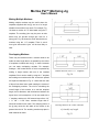
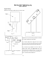
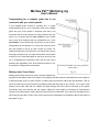
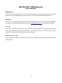
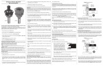
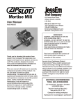
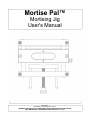
Mortise Pal™
Mortising Jig
User's Manual
Revision-C
COPYRIGHT © 2007 BY R.G. Jig Co.
WARNING: NO PORTION OF THIS MANUAL MAY BE REPRODUCED IN ANY SHAPE
OR FORM WITHOUT THE WRITTEN APPROVAL OF R.G. Jig Co.
Mortise Pal™ Mortising Jig
User's Manual
Thank you for your purchase. Mortise Pal™ allows you to make precision slot mortises with your plunge router. If
used properly, the jig should provide years of trouble free operation. Please take the time to thoroughly read this
manual and familiarize yourself with how the jig is used as well as the jig's safety precautions.
Kit Contents:
As shown in Fig. 1, the jig is supplied with:
●
(1) Jig Body
●
(4) Mortising Templates
●
(1) 3/32” Hex Key
Required Items:
To use the jig you will be required to supply:
●
A plunge router with a 6” base plate. The jig is
Kit Contents
designed to be use with smaller sized plunge
Fig. 1
routers with a 6” base plate. These routers are
generally 2-1/4 horsepower or less and weigh less than 12 pounds. The jig is not designed for and
should not be used with heavier plunge routers.
●
A router bit. Spiral up-cut bits are recommended as they remove waste from the mortise while routing.
●
A 5/8” outside diameter template guide. Please note that the collar on the template guide must be no
longer than 3/8” as shown in Fig. 2. A quality template guide with a centering pin is highly recommended.
We offer a precision template guide manufactured
by Whiteside Machine Company as an accessory.
Note: for best results in your joinery it is important
to install the template guide so that it is concentric
with your router spindle. A template guide that is
not concentric with the spindle can produce
unwanted problems with your joinery. A quality
template guide installed using a centering pin will
avoid this problem. If you choose not to use a
centering pin, please see the section on page 12
A 5/8” template guide with a 3/8” maximum
collar length is required.
for a tip on minimizing this problem.
Fig. 2
1
Mortise Pal™ Mortising Jig
User's Manual
Safety:
To operate this or any tool safely and efficiently, it is
essential to become as familiar as possible with its
characteristics. Take as much time as necessary to
become familiar with the jig. Also, read and follow all
of the safety procedures noted in this manual. If you
do not understand any of the operations or safety
guidelines discussed in this manual, please get
answers to all your questions before attempting to use
the jig by emailing [email protected] or calling
619-459-7951.
Read, understand, and follow all of the instructions
and safety guidelines that were included with your
plunge router.
Avoid this set-up
Proper workpiece holding is essential for the safe use
Fig. 3
of the jig. The workpiece must be held securely with
clamps, in a woodworkers vise, or by other suitable
means. A workpiece that is not properly secured could
move while routing, creating an unsafe situation or
damaging the jig.
When using a woodworker's vise avoid clamping the
jig to your stock as shown in Figures 3 and 4. The jig
is shown clamped to the stock with too much distance
between the jig and the vise jaws. Forces generated
from routing could leverage the stock and cause it to
move. Figures 5 and 6 illustrate a safer setup when
clamping stock in a woodworkers vise. The stock has
been repositioned so that the jig is closer to the vise
Avoid This Set-up.
jaws. Forces generated from routing are less likely to
leverage the stock.
Fig. 4
2
Mortise Pal™ Mortising Jig
User's Manual
This Set-up is O.K.
This set-up is O.K.
Fig. 5
Fig. 6
Specifications:
Referring to Fig. 7:
●
The minimum stock width is 1”. Your stock needs to be at least 1” wide to be securely clamped in the
jig.
●
The minimum stock thickness is 3/4”. Note, mortises may be made in thiner stock by using shims. See
the section on page 11 for details.
●
The maximum stock thickness is 2”.
●
The maximum mortise width is 1/2” as determined by the largest bit to fit through a 5/8” outside
diameter template guide.
●
The mortise length is determined by the template used and the diameter of the router bit used.
Referring to Fig. 8, the template length is measured from center to center along the slot. The templates
Stock and mortise specifications.
Template Specifications.
Fig. 7
Fig. 8
3
Mortise Pal™ Mortising Jig
User's Manual
supplied with the jig come in four lengths, 1/2”,
1”, 1 1/2” and 2”. To determine the overall
mortise length add the template length to the bit
diameter. For example, the 1” template used
with a 3/8” bit produces a 1-3/8”mortise. The
same template used with a 1/4” bit produces a
Template Length (in)
1/2
1
1 1/2
2
Bit Diameter (in)
3/4
1 1/4
1 3/4
2 1/4
1/4
Mortise Length (in)
13/16”
7/8
1 5/16”
1 3/8
1 13/16”
1 7/8
2 5/16”
2 3/8
5/16”
3/8
1
1 1/2
2
2 1/2
1/2
Mortise length equals template length plus bit
diameter.
Table 1
1-1/4” mortise. Table 1 can be used to determine
the overall mortise length for common sized
router bits. Note, by overlapping mortises it is possible to create mortises of virtually any length. Please
see the section on page 9 for details.
●
Referring again to Fig. 8, the template width is 41/64”, or 1/64” larger than a 5/8” template guide. This
small space between the template guide and the template allows you to rout the mortise by moving your
router around the template thereby producing a mortise with an excellent surface finish on the walls. Just
remember that your finished mortise will be 1/64” larger than the bit diameter. The recommended
technique for routing will be discussed in the section that follows.
Using the Jig:
Using the jig generally requires the following four steps:
1. Selecting and installing a template.
2. Making layout lines on your stock.
3. Setting up the jig.
4. Routing the mortise.
Step 1. Referring to Fig. 9, select a template and then
install it by first removing the brass screws. Use the
3/32” hex key that was included with the jig. Place the
template onto the jig body so that the holes in the
template mate with the corresponding dowel pins on the
jig body. Press down firmly to ensure that the holes in
the template mate with the dowel pins. The templates
are designed to mate with the dowel pins with a friction
Install template by removing brass screws and
placing template over dowel pins.
fit. Carefully replace the brass screws. To remove the
template, remove the brass screws, insert your index
finger into the slot on the template and pull it off of the jig body.
4
Fig. 9
Mortise Pal™ Mortising Jig
User's Manual
Step 2. Make layout lines on your stock that mark the
center of the mortise. Fig 10 shows the completed layout
lines on a leg blank before the mortise has been routed.
Step 3. Setting up the jig will require centering the
template over the layout lines. Referring to Fig. 11, hold
the jig's fence against the stock. Note, it is easiest to
perform this step with the jig not clamped to the stock.
Align the engraved mark on the side of the jig with the
first layout line as shown. When the engraved mark and
the layout line coincide, turn the thumb screw to lock
the template in place. Referring to Fig. 12 align the
pointer in the center of the jig with the second layout
line. Then turn the clamping knob so that the jig is
secured to the stock with the template centered over the
layout lines.
Make layout lines marking the center of the
mortise.
Fig. 10
Step 4. Proceed to rout the mortise with your plunge router fitted with a 5/8” template guide. Referring to Fig. 13,
Align engraved mark with first layout line.
Align pointer with second layout line.
Fig. 11
Fig. 12
5
Mortise Pal™ Mortising Jig
User's Manual
the recommended technique for routing the mortise is to
make a series of overlapping plunges to full depth along the
length of the template. Then make a finishing cut by moving
your plunge router around the template. As mentioned, the
template is sized 1/64” larger than the diameter of a 5/8”
template guide allowing you to use this technique. This
technique is fast and produces a mortise with an excellent
surface finish on the walls. Just remember that your mortise
will be 1/64” larger than the bit diameter.
Note, waste chips will accumulate while routing the mortise.
You may need to periodically stop routing and remove this
Overlapping plunge cuts.
Fig. 13
waste. A shop vacuum works well.
Tips and Techniques:
Practice first:
Practice using the jig on scrap pieces of material
before using it on expensive stock.
Use A Marking gauge: Using a marking gauge
or similar precision marking tool when making layout
lines will ensure consistency and create accuracy in
Marking reference surfaces and making layout
lines on leg assembly.
your joinery.
Fig. 14
6
Mortise Pal™ Mortising Jig
User's Manual
Layout From Common Reference Surfaces:
Making layout lines from common reference surfaces on
your stock will ensure that your mortises are accurately
located. Fig. 14 shows two legs to be joined in a table
assembly. The legs share common reference surfaces
that have been marked with the letters “F” and “T”. The
front reference surface has been marked with the letter
“F” on each leg. And the top reference surface has
been marked with the letter “T” on each leg. Layout lines
have been made on each leg referenced from those
Marking reference surfaces and making layout
lines on apron
surfaces. The resulting mortises made using the layout
Fig. 15
lines will be perfectly aligned with each other. Fig. 15
shows an apron with two sets of layout lines on the end grain. The two sets of layout lines have common
reference surfaces marked “F” and “T”. The layout
lines have been made referenced from those surfaces
and the resulting mortises will be perfectly aligned
with each other.
Keep the Fence in Contact With a
Common Reference Surface:
Clamping the jig to your stock with the fence in
contact with a common reference surface will ensure
accuracy. Fig. 16 shows the jig clamped to the leg
blanks previously discussed. Notice that the fence is
in contact with the front reference surface for both
mortises. Both mortises will be offset the exact same
distance from that surface. Note, even if you have set
up for mortises that are centered on your stock, it is
still good practice to use this technique. Any error in
Keep fence in contact with front reference surface
for both mortises.
laying out a centered mortise or error in aligning the
jig to the layout lines will be negated. Fig. 17 shows
Fig.16
7
Mortise Pal™ Mortising Jig
User's Manual
the jig clamped to the apron previously discussed.
Again notice that the fence is in contact with the front
reference surface for both mortises.
Keep fence in contact with front reference surface
for both mortises.
Fig. 17
Reduced Layout for Subsequent Mortises:
It is necessary that the first mortise made have two layout
lines that mark it's center. Subsequent mortises with the
same offset from the front reference surface require only one
layout line.
Fig. 18 shows the two leg blanks previously
discussed. Notice that one leg blank has a set of layout
lines and the other has just a single layout line. The jig will
be set up by centering the template over the set of layout
lines and routing the first mortise. Because the offset is the
same on the second mortise only one layout line referenced
from surface “T” is required. Align the jig's pointer to the
single layout line and rout the second mortise.
One set of layout lines for first mortise.
Single layout line is all that is needed for
subsequent mortises.
Fig. 18
8
Mortise Pal™ Mortising Jig
User's Manual
Making Multiple Mortises:
Making multiple mortises may be useful when the
templates supplied with the jig are not of a length
suitable for the width of your stock. For example, Fig.
19 shows a mortise in a 5” wide board using the 2”
template. The resulting joint may be prone to twist
and/or may not provide enough glue area for a
Single mortise with 2” template
strong joint. Fig. 20 shows the same board with two
Fig. 19
mortises using the 1-½” template. There is much
more glue area and the joint will be less likely to
twist.
Overlapping Mortises:
There may be instances when a mortise needs to be
made an exact length that is not possible by the choice
of templates included with the jig. In these instances
you can make overlapping mortises. For example,
making a 1-5/8” mortise with a 1/4” bit is not possible by
Double mortise with 1-1/2” template.
making a single mortise with one of the included
templates. But it can be made by using the 1” template
Fig. 20
and making two mortises with their centers are spaced
3/8” apart as illustrated in Fig. 21. Notice that two sets
of layout lines have been made marking the centers of
the overlapping mortises. The rule for calculating the
overall length of this mortise is to add the template
length, the bit diameter, and the distance between the
layout lines. In this example a 1/4” bit was used with a
1” template, and there is 3/8” between layout lines: 1/4”
+ 1”+ 3/8” = 1-5/8”. Note, mortises longer than 2”
should be avoided in thin stock. The clamping nature of
the jig may cause the thin walls of the mortise to be
pressed into the bit. The resulting mortise may taper in
width towards its center.
Overlap mortises to create a mortise
of virtually any length.
Fig. 21
9
Mortise Pal™ Mortising Jig
User's Manual
Angled Joinery:
Mortise Pal is extremely versatile and can be used to make
Rail joined to leg at angle.
Jig clamped to board at 45° for mitered
joinery.
Fig. 23
Fig. 22
angled joinery. Fig. 22 shows the jig clamped to a board at
45° to make a mortise for a mitered joint.
Fig. 23 shows a rail joined to a leg at 85° such as might
be found in a chair. Note that mortises have been made in
both parts so that they can be joined with a loose tenon.
Fig. 24 shows the jig clamped to the rail to make an
angled mortise. Notice that angled shims have been
Jig clamped to rail at angle using angled
shims.
inserted between the stock and the jig. The angled shims
have been made on the table saw by crosscutting a 1”
thick, 5” wide board with the blade at 5°.
Fig. 24
10
Mortise Pal™ Mortising Jig
User's Manual
Mortising in Stock Thinner than 3/4”:
Fig. 25 shows that stock thinner than 3/4” can not be
clamped in the jig without the use of shims. Notice that the
clamping jaw does not contact the stock when the
clamping knob is fully turned. Also notice that the
engraved mark used to center the template over layout
lines can not be centered on the thickness of this stock,
therefore it would not be possible to make a mortise
centered on the thickness of this board.
Additionally, Fig. 26 shows that the slot in the jig body is
Stock less than 3/4” can not be clamped in jig
without using shims.
11/16” wide x 3” long. Stock that is less than 11/16” thick
and less than 3” long would not register properly with the
Fig. 25
bottom of the jig. With these considerations in mind, the
recommended technique for mortising in stock thinner than
3/4” is to make a shim that is at least 1/2” thick, 5” wide and long enough that the stock can be clamped to it. Fig.
40 shows the stock clamped to the shim with the top of the shim and the top of the stock flush. Then the jig has
been clamped so that the top of the shim is registered to the bottom of the jig.
Stock smaller than slot dimensions will not
register properly to bottom of jig.
Stock clamped to shim first with top surfaces
flush. Then jig clamped to stock.
Fig. 26
Fig. 27
11
Mortise Pal™ Mortising Jig
User's Manual
Compensating for a template guide that is not
concentric with your router spindle:
If your template guide included a centering pin it is highly
recommended that you use it to perfectly center your template
guide with your router spindle. A template guide that is not
concentric with the router spindle can cause problems with your
joinery. Fig. 28 shows that the front surfaces of your boards
may not join flush, assuming that you intended them to, or the
top surfaces of your boards may not join flush, or both. A tip for
compensating for this problem is to orient your router the same
way with respect to the jig for each mortise you make. For
example always keep your left hand on the same side of the jig
as the jig's clamping knob. You might also make a mark or place
a sticker on your router base plate as well as on the jig to help
you in maintaining this orientation. Note, this will only correct
problems with registration of the front surfaces as shown in Fig.
41 and does not help with the top surfaces.
Making Loose Tenon Stock:
Template guide that is not concentric
with router spindle can cause problems
with joinery.
Fig. 41
Making perfect fitting loose tenon stock is best accomplished by
using a thickness planer and a set of calipers. Using calipers and the lead screw that adjusts the cutter height on
a thickness planer gives you great accuracy in making tenon stock that is exactly the right thickness. First, rip
stock on a table saw so that it's width is just slightly smaller than the length of your mortise. 1/32” is good. Then
measure the mortise width with the calipers and begin bringing the tenon stock to thickness on the planer.
Periodically check the thickness with the calipers. Adjust the cutter height as necessary by calculating the
number of turns that must be made to bring the tenon stock to final thickness. Then round over the edges of your
stock using a router table. Finally, cross cut the tenon stock to length based on the depth of the mortise leaving a
little space for glue.
12
Mortise Pal™ Mortising Jig
User's Manual
Maintenance:
The jig requires very little maintenance. To remove dust and debris from the jig use compressed air, a soft bristle
brush or a dry rag. Periodically place a drop of lubricant or tool oil on the four stainless steel guide rods.
Warranty:
R.G. Jig Co. stands behind its products with a one-year limited warranty. If you have any questions regarding the
warranty you can contact Customer Service by email at [email protected] or by calling 619-459-7951.
Coverage:
R.G. Jig Co. warrants that this product is free of defects in factory workmanship and materials during normal
use. If this product fails during normal use because of such a defect, R.G. Jig Co. will, at its option, repair or
replace, free of charge, any part or parts shown to be so defective.
Excluded from Coverage:
Failure resulting from alteration, modification, misuse, abuse or neglect or after repairs have been attempted or
made by others.
13