1
- MSD Turbo
Advanced IQ Software for IQ System Control and
Monitoring with an MS-DOS PC Host Computer
Version 1.4
© 1996 by Crown International, Inc., P.O. Box 1000, Elkhart, IN 46515-1000 U.S.A.
Telephone: 219-294-8000. Fax: 219-294-8329. IQ System components and
software are produced by the Professional Audio Division of Crown International, Inc.
Trademark Notice: MPX-6,™ SMX-6,™ AMB-5,™ Distributed Intelligence ™ and
SmartAmp™ are trademarks and Dataframe,® Amcron,® Crown,® IOC,® ODEP,® IQ
System ® and P.I.P.® are registered trademarks of Crown International, Inc. Other
trademarks are the property of their respective owners.
Printed on
recycled paper.
100234-1
12/96
IQ–MSD Turbo 1.4 Advanced IQ System Software
Crown Software License Agreement
This is a legal agreement between you, the end user, and Crown, a division of Crown International, Inc., 1718 West Mishawaka Road, Elkhart, Indiana 46517-4095 U.S.A. If you do not agree to the
terms of this agreement, promptly return the unopened disk package and the accompanying
items (including written materials and binders or other containers) to the place you obtained
them for a refund.
License
1. Crown grants to you the personal, non-exclusive right to use one copy of the enclosed software program (the “Software”) on a single computer at any one
time. A computer is hereby defined as one central processing unit and associated peripheral equipment, all at one location.
2. The Software is owned by Crown and is protected by United States copyright laws and international treaty provisions. Therefore, you must treat the Software like any other copyrighted material (such as a book or a musical recording) except that you may either (a) make one copy of the Software solely for
backup or archival purposes, or (b) transfer the Software to a single hard disk, provided you keep the original solely for backup or archival purposes. You may
NOT copy the written materials (the “documentation”) accompanying the Software.
3. You may NOT distribute copies of the Software to others or electronically transfer the Software from one computer to another over a network. The Software
contains trade secrets and to protect them you may NOT decompile, reverse engineer, disassemble, or otherwise reduce the Software to a human perceivable
form. You may NOT modify, adapt, translate, rent, lease, loan, resell for profit, distribute, network or create derivative works based upon the Software or any part
thereof. You may NOT transfer the Software and accompanying documentation on a permanent basis without first obtaining written authorization from Crown
and without the recipient agreeing to the terms of this Agreement.
4. This Agreement is effective until terminated. This Agreement is immediately terminated if you violate the terms and conditions hereof. You agree upon such
termination to destroy the Software together with all copies.
5. If the Software package contains both 3.5 and 5.25 inch disks, then you may use only the disks appropriate for your single-user computer. You may not use
the other disks on another computer or loan, rent, or transfer them to another user except as part of the permanent transfer (as provided above) of all Software
and documentation.
Limited Warranty
1. This Limited Warranty and any implied warranties are effective for a period of ninety (90) days from the date of delivery (the “Limited Warranty Period”) as
evidenced by a copy of your receipt. Crown warrants to you that the Software will perform substantially in accordance with the accompanying documentation
during the Limited Warranty Period. You must report all defects, and return the Software to the location where you obtained it with a copy of your receipt within
such period to be eligible for warranty service.
2. If the Software fails to comply with this Warranty, Crown will, at its option and cost, either provide all corrections required for any errors, replace the Software or refund the license fee for the Software.
3. CROWN DOES NOT AND CANNOT WARRANT THE PERFORMANCE OR RESULTS YOU MAY OBTAIN BY USING THE SOFTWARE OR DOCUMENTATION. THE FOREGOING STATES THE SOLE AND EXCLUSIVE REMEDIES FOR CROWN’S BREACH OF WARRANTY. EXCEPT FOR THE FOREGOING
LIMITED WARRANTY, CROWN MAKES NO WARRANTIES EXPRESS OR IMPLIED, AS TO NON-INFRINGEMENT OF THIRD PARTIES RIGHTS, OR FITNESS FOR ANY PARTICULAR PURPOSE. Some states or provinces do not allow the exclusion of implied warranties or limitations on how long an implied
warranty may last, so the above limitations may not apply to you. This warranty gives you specific legal rights. You may have other rights which vary from
state to state or province to province. For further warranty information you may contact Crown’s Technical Services Department at 57620 County Road 105,
Elkhart, Indiana 46517.
4. IN NO EVENT WILL CROWN BE LIABLE TO YOU FOR ANY CONSEQUENTIAL, INCIDENTAL OR SPECIAL DAMAGES, INCLUDING ANY LOST PROFITS OR LOST SAVINGS, EVEN IF A CROWN REPRESENTATIVE HAS BEEN ADVISED OF THE POSSIBILITY OF SUCH DAMAGES, OR FOR ANY CLAIM
BY ANY PARTY. Some states do not allow the exclusion or limitation of incidental, consequential or special damages, so the above limitation or exclusion
may not apply to you.
5. This Agreement shall be governed by the laws of the State of Indiana.
U.S. Government Restricted Rights
The Software and documentation are provided with RESTRICTED RIGHTS. Use, duplication, or disclosure by the Government is subject to the restrictions set
forth in subparagraph (c)(1)(ii) of the Rights in Technical Data and Computer Software clause at 52.227-7013.
Should you have any questions concerning this Agreement, please contact Crown’s Technical Services Department at 57620 County Road 105, Elkhart, Indiana 46517.
12/91
Page 2
IQ–MSD Turbo 1.4 Advanced IQ System Software
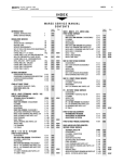
Contents
C
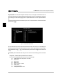
1 Introducing IQ–MSD Turbo ................................................................................ 11
1.1
1.2
1.3
1.4
1.5
1.6
System Requirements ...............................................................................................................
About This Manual ...................................................................................................................
Technical Support .....................................................................................................................
Installation .................................................................................................................................
For Experienced Users ............................................................................................................
What’s New in Version 1.4 ........................................................................................................
12
12
13
14
15
15
2 Using Turbo ......................................................................................................... 17
2.1
Basic Concepts .........................................................................................................................
2.1.1 Text Screens ...............................................................................................................
2.1.2 Graphics Plates ...........................................................................................................
2.1.3 Perspective .................................................................................................................
2.2 Starting the Program .................................................................................................................
2.2.1 Optional Command Line Parameters ...........................................................................
2.3 Establishing Communication ......................................................................................................
2.4 Setting Turbo’s System Parameters ..........................................................................................
2.5 Using Control Blocks ................................................................................................................
2.5.1 The Parts of a Control Block ........................................................................................
2.5.2 Navigating Control Blocks & Setting Controls ..............................................................
• Moving from One Control Block to Another ..............................................................
• Adding a New Control Block ....................................................................................
• Selecting a Control or Text Line ...............................................................................
• Setting an On/Off Control ..........................................................................................
• Setting a Level Control .............................................................................................
• Setting a Range Control ...........................................................................................
• Moving from a Control Block to a Sub-block ............................................................
2.6 Using Sub-blocks ......................................................................................................................
2.6.1 Navigating Sub-blocks & Setting Controls ...................................................................
• Moving from One Sub-block or Sub-block Screen to Another ..................................
• Moving Among Sub-blocks of Similar Components ..................................................
• Locally Copying & Pasting in a Mixer Sub-block .....................................................
• Globally Copying & Pasting Between IQ Components .............................................
• Restore Default Settings to All the Sub-blocks of an IQ Component ..........................
• Moving from a Sub-block Back to a Control Block ....................................................
2.7 Activating Emergency Mute ......................................................................................................
2.8 Using Graphics Plates ...............................................................................................................
2.8.1 The Graphics Plate Control Block Screen ...................................................................
2.8.2 Using the Graphics Plate Control Block from the Graphics Plate ..................................
2.9 Saving and Loading Dataframe Files .......................................................................................
2.10 Printing the IQ System Settings .................................................................................................
2.11 Checking Memory ....................................................................................................................
17
18
20
21
22
22
23
25
30
32
32
32
33
33
33
33
33
33
34
35
35
35
35
36
36
36
37
38
39
40
42
43
44
Page 3
IQ–MSD Turbo 1.4 Advanced IQ System Software
3 Designing Graphics Plates ................................................................................ 45
C
3.1
Overview .................................................................................................................................
3.1.1 A Simple Example .......................................................................................................
3.1.2 Graphics Plate Design Principles .................................................................................
3.2 Creating a New Graphics Plate ................................................................................................
3.3 Adding Objects to a Graphics Plate ...........................................................................................
3.3.1 Toolbox .......................................................................................................................
3.3.2 Resizing an Object ......................................................................................................
3.3.3 Moving One or More Objects ......................................................................................
3.3.4 “Autosizing” an Object .................................................................................................
3.3.5 Changing the Attributes of an Object ............................................................................
3.3.6 Copying and Pasting an Object ...................................................................................
3.4 Deleting an Object from a Graphics Plate ..................................................................................
3.5 Adding a New IQ Component from a Graphics Plate ................................................................
3.6 Copying and Pasting an Entire Graphics Plate .........................................................................
3.7 Restoring a Graphics Plate to a “New” Condition .....................................................................
3.8 The Crown IQ Icon ..................................................................................................................
3.9 How to Create a Custom GDM .................................................................................................
3.9.1 Preparing an OIF ........................................................................................................
3.9.2 Exit and Restart Turbo ................................................................................................
3.9.3 Creating a GDM Container .........................................................................................
3.9.4 Adding Objects to the GDM Container .........................................................................
3.9.5 Saving the GDM .........................................................................................................
3.10 Saving a Graphics Plate ...........................................................................................................
45
45
48
49
53
53
55
56
58
59
60
61
61
62
62
62
63
63
64
64
66
68
69
4 Object Reference ............................................................................................... 71
4.1
4.2
4.3
4.4
4.5
4.6
4.7
4.8
4.9
4.10
4.11
4.12
4.13
4.14
4.15
4.16
4.17
4.18
Page 4
Graphic Display Module (GDM) ............................................................................................... 71
Pot ............................................................................................................................................ 73
On/Off Button ............................................................................................................................. 76
Bar Meter ................................................................................................................................. 79
Digital Meter .............................................................................................................................. 81
LED .......................................................................................................................................... 83
Text ........................................................................................................................................... 85
Container ................................................................................................................................. 88
Clock ........................................................................................................................................ 91
Spin Control .............................................................................................................................. 92
System Button ........................................................................................................................... 94
GDM Container ........................................................................................................................ 97
Mini Plate ................................................................................................................................ 100
Line ......................................................................................................................................... 103
Drone Objects ........................................................................................................................ 104
Plotter ..................................................................................................................................... 108
Curve ...................................................................................................................................... 111
String ....................................................................................................................................... 113
IQ–MSD Turbo 1.4 Advanced IQ System Software
5 Monitoring & Controlling Amplifiers ............................................................... 115
5.1
5.2
5.3
5.4
5.5
Initializing an Amplifier Control Block ......................................................................................... 116
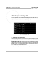
Monitoring an Amplifier ............................................................................................................. 118
5.2.1 Monitoring from a Control Block ................................................................................. 118
5.2.2 Monitoring from a Display Screen .............................................................................. 118
5.2.3 Monitoring from a Graphics Plate ............................................................................... 120
Manual Controls ..................................................................................................................... 121
5.3.1 Manual Control from a Control Block ......................................................................... 121
5.3.2 Global Amplifier Controls ............................................................................................ 123
5.3.3 Manual Control from a Graphics Plate ....................................................................... 124
Automated Controls ................................................................................................................ 125
5.4.1 ODEP Conservation ................................................................................................. 126
5.4.2 Smooth Output Limiter ................................................................................................ 126
5.4.3 Stand By ................................................................................................................... 127
5.4.4 Error Reporting ......................................................................................................... 127
5.4.5 Input Compressor ..................................................................................................... 128
DSP Controls .......................................................................................................................... 129
5.5.1 Signal Delay ............................................................................................................. 129
5.5.2 Programmable Filters ................................................................................................ 129
6 Monitoring & Controlling Mixers .................................................................... 133
6.1
6.2
6.3
6.4
Initializing a Mixer Control Block .............................................................................................. 133
Monitoring a Mixer ................................................................................................................. 134
6.2.1 Monitoring from a Display Screen ............................................................................. 134
6.2.2 Monitoring from a Graphics Plate ............................................................................... 137
Manual Controls ..................................................................................................................... 138
6.3.1 Manual Control from a Control Block ......................................................................... 138
6.3.3 Manual Control from a Graphics Plate ....................................................................... 140
Automated Controls ................................................................................................................ 141
6.4.1 Gate Function ............................................................................................................ 143
6.4.2 Duck Priority Function ............................................................................................... 145
6.4.3 Input Compressor/Limiter Function ............................................................................ 146
6.4.4 Auto Level Function .................................................................................................. 148
6.4.5 Output Compressor/Limiter Function ......................................................................... 151
6.4.6 Gate Count Function ................................................................................................. 153
6.4.7 External Functions (SMX-6 Mixers Only) ................................................................. 154
6.4.8 SMX Interrupts Function (SMX-6 Mixers Only) ......................................................... 156
6.4.9 Mute Function (SMX-6 Mixers Only) ......................................................................... 157
6.4.10 AMB Function (AMB-5 Mixers Only) ........................................................................ 159
7 Monitoring & Controlling Equalizers ............................................................. 163
7.1
7.2
7.3
Initializing an Equalizer Control Block ...................................................................................... 163
Monitoring an Equalizer .......................................................................................................... 164
Manual Controls ..................................................................................................................... 165
7.3.1 Manual Control from a Control Block ......................................................................... 165
7.3.2 Manual Control from a Graphics Plate ....................................................................... 166
Page 5
C
IQ–MSD Turbo 1.4 Advanced IQ System Software
8 Monitoring & Controlling Drones ................................................................... 169
C
8.1
8.2
8.3
8.4
8.5
8.6
Initializing a Drone Control Block ............................................................................................. 169
Monitoring a Drone ................................................................................................................ 170
8.2.1 Monitoring from a Control Block ................................................................................ 170
8.2.2 Monitoring from a Graphics Plate ............................................................................... 170
Manually Controlling a Drone ................................................................................................. 171
8.3.1 Manual Control from a Control Block ......................................................................... 171
8.3.3 Manual Control from a Graphics Plate ....................................................................... 172
Control Block Shortcuts ........................................................................................................... 172
Training a Drone .................................................................................................................... 173
8.5.1 AUX Input Setup ....................................................................................................... 174
8.5.2 Simplex-Mode Assignments ...................................................................................... 175
8.5.3 Binary-Mode Assignments ........................................................................................ 180
8.5.4 Analog Input Assignments ......................................................................................... 182
8.5.5 AUX Output Assignments ........................................................................................... 184
8.5.6 Paralyze Setup ......................................................................................................... 186
Linking Multiple Drones ........................................................................................................... 173
9 Monitoring & Controlling Matrixers ............................................................... 189
9.1
9.2
9.3
Initializing a Matrixer Control Block .......................................................................................... 189
Using a Control Block to Monitor & Control a Matrixer ............................................................ 190
Using a Graphics Plate to Monitor & Control a Matrixer .......................................................... 191
10 Monitoring & Controlling a PSI ...................................................................... 193
10.1 Initializing a PSI Control Block ................................................................................................. 193
10.2 Using a Control Block to Monitor & Control a PSI ................................................................... 194
10.3 Using a Graphics Plate to Monitor & Control a PSI ................................................................. 194
11 Configuring & Monitoring System & Load Monitors .................................... 195
11.1 Initializing an SLM-8 Control Block .......................................................................................... 195
11.2 Monitoring an SLM-8 .............................................................................................................. 196
11.2.1 Monitoring from a Control Block ................................................................................ 196
11.2.2 Monitoring from a Curve Screen ............................................................................... 196
11.2.3 Monitoring from a Graphics Plate ............................................................................... 197
11.2.4 Using a Monitor Speaker .......................................................................................... 198
11.3 Configuring an SLM-8 ............................................................................................................ 198
11.4 Manual Controls ..................................................................................................................... 201
11.5 Exporting Data from an SLM-8 ............................................................................................... 202
G Glossary of Terms ............................................................................................. 203
A Appendices ....................................................................................................... 213
I Index ........................................................................................................................
215
Page 6
IQ–MSD Turbo 1.4 Advanced IQ System Software
Illustrations
1.1
2.1
2.2
2.3
2.4
2.5
2.6
2.7
2.8
2.9
2.10
2.11
2.12
2.13
2.14
2.15
2.16
2.17
2.18
2.19
2.20
2.21
2.22
2.23
2.24
2.25
2.26
2.27
2.28
2.29
2.30
3.1
3.2
3.3
3.4
3.5
3.6
3.7
3.8
3.9
3.10
3.11
3.12
3.13
3.14
3.15
3.16
3.17
3.18
A Sample Turbo Graphics Plate Showing Custom Objects .............................................................................. 11
Sample Text Screen and Graphics Plate ........................................................................................................ 17
The Main Control Panel Screen ..................................................................................................................... 18
An Amplifier Control Block Screen .................................................................................................................. 18
A 6-Bar Amplifier Display Screen ................................................................................................................... 19
An Amplifier Sub-block Screen ....................................................................................................................... 19
A Sample Graphics Plate ............................................................................................................................... 20
Putting Text Screens and Graphics Plates into Perspective ............................................................................ 21
The Turbo Title Screen .................................................................................................................................. 22
No Interface Found Message ......................................................................................................................... 23
Looking for Interface Message ........................................................................................................................ 23
A Typical Roll Call ......................................................................................................................................... 24
Control Panel Screen ..................................................................................................................................... 25
System AUX Setup Screen ............................................................................................................................ 28
The Device Menu .......................................................................................................................................... 30
An SMX Control Block Screen ....................................................................................................................... 30
An SMX Control Block from a Graphics Plate ................................................................................................. 31
A Closer Look at a Control Block ................................................................................................................... 32
An Amplifier Sub-block Screen for an IQ–P.I.P.–SMT ..................................................................................... 34
The First of Four SMX-6 Mixer Sub-block Screens ........................................................................................ 34
A Sample Sub-block Help Window ................................................................................................................. 36
The Emergency Mute Screen ........................................................................................................................ 37
A Graphics Plate Under Construction ............................................................................................................. 38
The Graphics Plate Control Block Screen ....................................................................................................... 39
The Graphics Plate Version of the Graphics Plate Control Block ..................................................................... 40
The File Menu ............................................................................................................................................... 42
The Dataframe File List Window ................................................................................................................... 43
The Print Select Components Menu ............................................................................................................... 43
A Portion of a Sample Printout ........................................................................................................................ 44
Checking Available Memory from a Control Block Screen ............................................................................. 44
Checking Available Memory from a Graphics Plate ....................................................................................... 44
The Graphic Display Module (GDM) for an IQ–P.I.P.–MEM ........................................................................... 46
The Objects Used for the Graphics Plate Design Example ............................................................................. 46
The Combined Objects for the Graphics Plate Design Example ...................................................................... 47
Begin a New Graphics Plate at the Graphics Plate Control Block Screen ....................................................... 49
The Graphics Setup Window .......................................................................................................................... 50
A Graphics Plate with a Stadium Picture in the Background ............................................................................ 51
The Graphics Plate Attributes Window ............................................................................................................ 51
An Empty Graphics Plate with a Visible Grid .................................................................................................. 52
The Graphics Plate Toolbox ........................................................................................................................... 53
The Select Component Window for a GDM Object ......................................................................................... 54
The Pointer Changes to Aid Placement of the New Object ............................................................................. 54
A GDM With a Legend (Left) and Without a Legend (Right) .............................................................................. 55
Resizing an Object ......................................................................................................................................... 55
Restoring an Object to Its Default Size ............................................................................................................. 56
Moving a Single Object .................................................................................................................................. 56
Grouping Multiple Objects ............................................................................................................................... 57
Moving a Group of Objects ............................................................................................................................ 57
“Autosizing” an Object .................................................................................................................................... 58
Page 7
C
IQ–MSD Turbo 1.4 Advanced IQ System Software
C
3.19
3.20
3.21
3.22
3.23
3.24
3.25
3.26
3.27
3.28
3.29
3.30
4.1
4.2
4.3
4.4
4.5
4.6
4.7
4.8
4.9
4.10
4.11
4.12
4.13
4.14
4.15
4.16
4.17
4.18
4.19
4.20
4.21
4.22
4.23
4.24
4.25
4.26
4.27
4.28
4.29
4.30
4.31
4.32
4.33
4.34
4.35
4.36
4.37
4.38
4.39
Page 8
The GDM Attributes Window for a Legacy IQ P.I.P. ........................................................................................ 59
The Pot Attributes Window ............................................................................................................................. 60
The Add Component Window ........................................................................................................................ 61
The Crown IQ Icon ........................................................................................................................................ 62
ID Codes for OIFs .......................................................................................................................................... 64
GDM Container Attributes Window .................................................................................................................. 65
A GDM Container ........................................................................................................................................... 66
The Unassembled Custom GDM ................................................................................................................... 66
The Assembled Custom GDM ....................................................................................................................... 67
The Custom GDM Save Dialog Box .............................................................................................................. 68
The New GDM Replaces the Standard One That Came With Turbo ............................................................... 68
A Prompt to Store Changes Into Memory Before Exiting a Graphics Plate ...................................................... 69
The Graphics Plate Toolbox ........................................................................................................................... 71
GDM Select Component Window ................................................................................................................... 72
The Pot Attributes Window ............................................................................................................................. 73
Sample Pot Objects ....................................................................................................................................... 75
The Legend Automatically Scales to Fit the Pot .............................................................................................. 75
The Pointer Changes to a Hand When the Pot Handle is Clicked or Dragged .................................................. 75
The Button Attributes Window ......................................................................................................................... 76
A Sample Button ............................................................................................................................................ 78
Bar Meter Attributes Window .......................................................................................................................... 79
Sample Bar Meter Objects ............................................................................................................................. 80
The Legend Automatically Scales to Fit the Bar Meter .................................................................................... 80
The Digital Meter Attributes Window ................................................................................................................ 81
A Sample Digital Meter ................................................................................................................................... 82
The LED Attributes Window ............................................................................................................................ 83
Sample LED Objects ...................................................................................................................................... 84
The Text Attributes Window ............................................................................................................................ 85
Sample Fonts ................................................................................................................................................ 86
Sample Font Sizes ......................................................................................................................................... 86
Editing the Text in a Text Object ..................................................................................................................... 87
Moving a Text Object .................................................................................................................................... 87
A Text Object on an On/Off Button Object ....................................................................................................... 87
The Container Attribute Window ...................................................................................................................... 88
A Sample Empty Container Object ................................................................................................................. 89
A Sample Container Used to Create an MRX-24 Control Panel ...................................................................... 89
Normally New Containers Are Layered on Top of Older Containers ............................................................... 90
Moving a Container to the Front of Another Container ..................................................................................... 90
The Clock Attributes Window ......................................................................................................................... 91
A Sample Clock ............................................................................................................................................. 91
The Spin Control Attributes Window ................................................................................................................ 92
Sample Spin Controls .................................................................................................................................... 93
The System Button Attributes Window ............................................................................................................ 94
Dataframe Files Must Be Stored in the Turbo Directory .................................................................................. 95
The Select Mini Plate Window ........................................................................................................................ 95
A System Button ............................................................................................................................................ 96
The GDM Container Attributes Window ........................................................................................................... 97
The Custom GDM Save Dialog Box .............................................................................................................. 98
A GDM Container ........................................................................................................................................... 99
The Mini Plate Attributes Window ................................................................................................................. 100
A Mini Plate Container Object ....................................................................................................................... 101
IQ–MSD Turbo 1.4 Advanced IQ System Software
4.40
4.41
4.42
4.43
4.44
4.45
4.46
4.47
4.48
4.49
4.50
4.51
4.52
4.53
4.54
4.55
4.56
4.57
4.58
4.59
4.60
5.1
5.2
5.3
5.4
5.5
5.6
5.7
5.8
5.9
5.10
5.11
5.12
5.13
6.1
6.2
6.3
6.4
6.5
6.6
6.7
6.8
6.9
6.10
6.11
6.12
6.13
6.14
6.15
6.16
6.17
The Select Mini Plate Window ...................................................................................................................... 102
The Line Attributes Window .......................................................................................................................... 103
Two Sample Line Objects ............................................................................................................................ 103
The Drone Object Attributes Window ............................................................................................................ 104
The Aux Input Drone Container Attributes Window ........................................................................................ 104
The Analog Input Drone Container Attributes Window .................................................................................... 105
The Binary Input Drone Container Attributes Window .................................................................................... 105
The Aux Output Drone Container Attributes Window ..................................................................................... 106
The Paralyze Drone Button Attributes Window .............................................................................................. 106
A Drone Container (Left) and Drone Paralyze Button (Right) .......................................................................... 107
The Plotter Attributes Window ....................................................................................................................... 108
The Plotter Setup Window ............................................................................................................................ 108
A Sample Plotter Object ................................................................................................................................ 109
A Plotter Object with a Curve Object ............................................................................................................ 109
The Plotter Cursor Displays the Value of Each Graph Coordinate .................................................................. 110
The Curve Attributes Window ....................................................................................................................... 111
One Curve Object on a Plotter Object ............................................................................................................ 112
Two Curve Objects on a Plotter Object ......................................................................................................... 112
An Unlinked Curve Object on the Graphics Plate .......................................................................................... 112
The String Attributes Window ......................................................................................................................... 113
A Sample String Object ................................................................................................................................. 114
A Typical Amplifier Control Block Screen ...................................................................................................... 115
The Control Blocks of Each IQ P.I.P. Model ................................................................................................... 116
Available IQ2 P.I.P. Models List .................................................................................................................... 117
Amplifier Model List ....................................................................................................................................... 117
A 6-Bar Amplifier Display Screen .................................................................................................................. 119
An 8-Bar Amplifier Display Screen ................................................................................................................. 119
Monitoring Amplifiers with Graphics Display GDMs ...................................................................................... 120
An Amplifier Control Block Screen ................................................................................................................ 121
The Amplifier “All” (Global) Controls ............................................................................................................. 123
Manual Amplifier Control with Custom Controls on a Graphics Plate ............................................................. 124
An Amplifier Sub-block Screen for a Legacy IQ P.I.P. ................................................................................... 125
An Amplifier Sub-block Screen for an IQ2 P.I.P. ........................................................................................... 125
An Amplifier DSP Sub-block Screen ............................................................................................................. 129
The Control Block of Each IQ Mixer Model .................................................................................................. 133
The SMX-6 Display Screen .......................................................................................................................... 134
A Single Input from an SMX-6 or AMB-5 Display Screen ............................................................................... 135
The MPX-6 Display Screen .......................................................................................................................... 136
Monitoring a Sensing IQ Mixer with a Graphics Plate GDM .......................................................................... 137
An SMX-6 Control Block Screen .................................................................................................................. 138
Turning the SMX-6 Lock Feature On Sets All Gain Controls to –100 dB ........................................................ 139
Manual Mixer Control with Custom Controls on a Graphics Plate ................................................................. 140
The First SMX-6 Sub-block Screen .............................................................................................................. 141
The First AMB-5 Sub-block Screen .............................................................................................................. 141
The Second SMX-6 Sub-block Screen ......................................................................................................... 146
The Third SMX-6 Sub-block Screen ............................................................................................................. 148
The Fourth SMX-6 Sub-block Screen ........................................................................................................... 151
The External Function (Algos) Window ......................................................................................................... 154
Turning On the SMX Interrupts Function Will Disable the Ch-2 Output Comp/Limiter ...................................... 156
Turning On the Mute Function Will Disable the Ch-2 Gate Count Function ..................................................... 157
The Mute Feature of an SMX-6 .................................................................................................................... 157
Page 9
C
IQ–MSD Turbo 1.4 Advanced IQ System Software
C
6.18
7.1
7.2
7.3
7.4
8.1
8.2
8.3
8.4
8.5
8.6
8.7
8.8
8.9
8.10
8.11
8.12
8.13
9.1
9.2
10.1
10.2
11.1
11.2
11.3
11.4
11.5
11.6
The Fifth AMB-5 Sub-block Screen ............................................................................................................... 159
A Typical Equalizer Control Block Screen .................................................................................................... 163
The Input/Output Level Bar Graphs on an Equalizer GDM ............................................................................ 164
A Typical Equalizer Control Block ................................................................................................................ 165
A Sample Equalizer GDM ............................................................................................................................. 166
A Drone Control Block Screen ...................................................................................................................... 169
Sample Objects Used to Monitor a Drone ..................................................................................................... 170
The Drone Object Attributes Window ............................................................................................................ 173
The Drone Aux Input Setup Sub-block Screen .............................................................................................. 174
The Drone Simplex Input Commands Sub-block Screen .............................................................................. 175
Adding a Command Assignment to a Simplex AUX Input ............................................................................. 176
Selecting an Existing Drone Command Assignment ..................................................................................... 179
Adding a Command Assignment to a Binary AUX Input ................................................................................ 181
Adding a Command Assignment to an Analog Input ..................................................................................... 182
Adding a Command Assignment to an AUX Output ...................................................................................... 184
Adding a Paralyze Command Assignment to an AUX Input .......................................................................... 186
Adding a Paralyze Command Assignment to an Analog Input ....................................................................... 187
The Drone Control Block with the Transponder Switch Enabled ................................................................... 188
The Matrixer Control Block Screen .............................................................................................................. 189
Monitoring & Controlling a Matrixer from a Graphics Plate ............................................................................. 191
The PSI Control Block Screen ..................................................................................................................... 193
Monitoring & Controlling a PSI from a Graphics Plate ................................................................................... 194
An SLM-8 Control Block Screen ................................................................................................................... 195
The SLM-8 Setup Sub-block Screen ............................................................................................................ 196
A Sample Impedance Curve ........................................................................................................................ 197
A Sample Graphics Plate Plotter Object with Two Curves ........................................................................... 197
The SLM-8 Setup Sub-block Screen ............................................................................................................ 198
Exporting Data to a DIF File .......................................................................................................................... 202
Page 10
IQ–MSD Turbo 1.4 Advanced IQ System Software
O
R
O
AU
D
I
C ONT
L
1
1 Introducing IQ–MSD Turbo
O
W
N
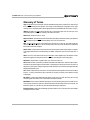
Welcome to the Crown IQ–MSD Turbo program—software that brings the powerful monitor and control capabilities of your IQ audio system to your PC-compatible computer. This manual will describe the use of version 1.4 of
IQ–MSD Turbo, referred from here on simply as Turbo.
With Turbo you can monitor and control your audio system from a remote location. It works with Crown’s
acclaimed IQ components, sophisticated audio components that are designed to work with Crown’s patented IQ
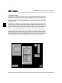
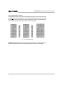
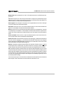
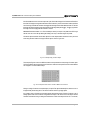
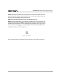
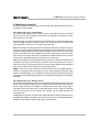
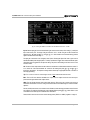
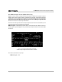
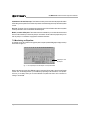
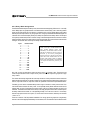
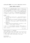
System®. But Turbo does much more than just monitor or control an IQ System. It also allows you to design, save
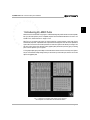
and reuse custom screens. We call these screens graphics plates (shown below) and they give you amazing
power over the operation of your IQ System.
A Turbo graphics plate gives you the ability to control what others can and cannot see or do with your IQ System.
And you can make them visually exciting and easy to use because you control the layout, size and color of each
object on the graphics plate.
Fig. 1.1 A Sample Turbo Graphics Plate Showing Custom Objects for
Seven Amplifiers, One SMX-6 Mixer and One MRX-24 Matrixer
Page 11
CR
IQ–MSD Turbo 1.4 Advanced IQ System Software
1.1 System Requirements
• A 33 MHz Intel® 80486 PC-compatible computer (recommended: 75 MHz Pentium).
• DOS 5.0 or higher with HIMEM.SYS and EMM386.EXE loaded.
1
• At least 8 megabytes (MB) of random-access memory (RAM) with at least 512 kilobytes (KB) of free conventional memory and no less than 3072 KB of free extended memory.
• A hard disk with at least 5 MB of free space.
• A VGA 16-color display adapter or better.
• A mouse or other compatible pointing device (a three-button mouse and appropriate DOS driver is recommended).
• A 3½-inch floppy disk drive.
• An RS232 (COM) port that uses a 16550-compatible UART.
• An optional printer (if desired) for producing lists of system settings.
1.2 About this Manual
This User Manual is written for the IQ System Administrator—the individual responsible for installing and configuring the system and its software. It explains the features of Turbo but it does not tell you how to use them. Because
the details of specific audio systems vary widely, this manual does not attempt to be an operation manual for your
system. It is assumed that the IQ System Administrator (or whatever title you choose to use) will provide proper
training to the operators in the specifics of the audio system and this software. Crown offers an IQ School to
assist with the training and certification of IQ System designers, installers and administrators. Please contact us if
you would like more information about our IQ training program.
Before installing Turbo, we recommend that you read the installation instructions. Experienced users can then
skip to relevant sections later in the manual to learn about specific software features for various IQ components.
The Using Turbo Section is intended for first-time Turbo users who would like an overview of the program before
delving into the details.
In order to limit the scope of this manual, a few assumptions are made on the part of the user. First, the user is
assumed to be knowledgeable in the use of personal computers and is familiar with principles of audio and IQ
Systems. Second, the user is assumed to understand the requirements for his/her audio application and is able
to determine the system settings to achieve the desired results.
Page 12
IQ–MSD Turbo 1.4 Advanced IQ System Software
The typographical conventions used in this manual are listed below:
Style
Meaning
Bold
Indicates important passages which should be read. It also indicates an important keyword
or keyphrase.
Bold Italics
Indicates a helpful tip.
Italics
Indicates a note. It is also used to emphasize a word or tradename.
T y p e w r i t e r Indicates something that should be typed exactly as shown.
1 0 Z Y
(Text or symbols inside a box with rounded corners) Indicates one or more specific keys on
the keyboard.
! @ #
Indicates function keys.
A+Z
Indicates that the first key should be depressed first and held down while the second key is
pressed.
{
Indicates a mouse action.
1.3 Technical Support
This software is backed by Crown’s technical support system. If you need assistance that this manual does not
provide, proceed as follows:
• If a problem occurs, attempt to duplicate it keystroke by keystroke in an effort to identify the point at which it
occurs.
• Take note of the software version number and date. This information is displayed on the start up screen.
• Take note of the date and version number of the manual. This information is at the lower right corner of the inside
title page.
• Have the details of your computer’s configuration available (a printout of the AUTOEXEC.BAT and
CONFIG.SYS files may be useful) and have the computer running Turbo when you call.
Crown Professional Audio Division
Technical Support / Factory Service
Plant 2 SW, 1718 W. Mishawaka Rd., Elkhart, Indiana 46517 U.S.A.
Telephone:
Fax:
219-294-8200 or 800-342-6939 (N. America, Puerto Rico & Virgin Islands only)
219-294-8301
Fax Back:
219-293-9200 (North America only) or 800-294-4094 (North America only)
219-294-8100 (International)
Internet:
http://www.crownintl.com
Page 13
1
IQ–MSD Turbo 1.4 Advanced IQ System Software
1.4 Installation
1
Turbo is a DOS-based program. Therefore, while Turbo can run under other operating systems (refer to
Appendix A for information on additional operating systems such as Microsoft® Windows®), the most straightforward installation and operation is under DOS. This manual assumes that the software is being run under DOS 5.0
or 6.xx.
DOS 5.0 and 6.xx use HIMEM.SYS and EMM386.EXE to manage computer memory. So, both of these files must
be in memory for Turbo to run correctly.
Before opening the diskette envelope and installing the program, please read the Software License printed on the
envelope. By opening the envelope, you agree to all of the terms of the Software License. In summary, Crown
grants a limited license to use Turbo on only one computer at a time. Please contact Crown if you need to
simultaneously run Turbo on more than one computer or on a network.
1 It is considered good practice to install software from a working copy. Therefore, make a copy of each of
the disks and use the working copy (backup) for the installation. Store the originals and backup in
separate locations away from magnetic fields and temperature and humidity extremes.
2 Turbo is NOT compatible with some third party memory management software—especially if that software
has DPMI services. As a result, if you are using a third party memory manager with DPMI, disable it and
enable HIMEM.SYS and EMM386.EXE. Since memory managers are usually loaded by CONFIG.SYS
as part of the boot routine, it will probably be necessary to modify CONFIG.SYS to accomplish this. Refer
to the Appendix A for more information.
3 Boot up your computer. Many systems are set up to automatically load and execute Microsoft Windows.
If this is the case with your computer, exit Windows and return to the DOS prompt. Insert Turbo disk 1 into
your floppy drive, and switch to that drive by typing a:E or b:E as appropriate, depending on
the floppy drive’s designation in your computer.
4 After the computer displays the DOS prompt from Step 3, type installE.
5 After a brief delay, you should be prompted for the name of the directory where you want Turbo to be
installed. Press E to accept the default directory (turbo) or enter the name of the directory you wish to
use. The installation program creates the directory if it does not already exist. Note: Some files may be
overwritten if Turbo is installed into the same directory as an older version.
All files are then created and copied into the directory. These files are:
TURBO14.EXE
The Turbo program.
TURBO13.GXL
A library file consisting of fonts, graphic images, and other associated material.
RTM.EXE
A memory manager required by Turbo’s protected mode.
DPMI16BI.OVL
A DPMI server required for the protected mode.
Page 14
IQ–MSD Turbo 1.4 Advanced IQ System Software
TURBO14.PIF
A sample PIF file for running Turbo under Microsoft Windows (refer to the Appendix).
TURBO14.ICO
An icon file that can be used with Microsoft Windows.
###.OIF
Several object information files (ending with the extension OIF) are provided for various IQ2
compatible components.
###.GDM
Several graphic display module files (ending with the extension GDM) are provided for
various IQ2 compatible components.
###.PCX
Several bitmap files (ending with the extension PCX) are provided to support the graphic
display modules of various IQ2 compatible components.
1.5 For Experienced Users
If you are already an experienced Turbo user, you may be eager to begin using Turbo without reading further.
Feel free to do so and refer to the manual as needed. To run the program, type turbo14 on the DOS
command line after it has been installed.
One important change to note is that s (the S key) is no longer used to enter a negative number— negative
numbers are now indicated by preceeding the number with the minus key.
1.6 What’s New in Version 1.4
• Support for new IQ2 components like the SLM-8 system and load monitor and new IQ P.I.P.s like the IQ–P.I.P.–
MEM, IQ–P.I.P.–SMT and IQ–P.I.P.–DSP.
• New DSP Sub-block screen for IQ P.I.P.s with digital signal processing capability.
• A new input compressor function has been added to all IQ2 P.I.P.s with SmartAmp automation features.
• Improvements to the user interface add consistency. For example, you can use the minus key to enter a
negative number into a level control.
• New graphics plate objects like the Plotter, Curve and String objects.
• Enhanced error reporting.
• Support for the PSI (Pocket Serial Interface), a new and portable IQ interface.
• Support for “System AUX”, the ability for an IQ AUX port on any IQ component to trigger changes in the IQ
System by loading the system settings in a predetermined dataframe file.
• The ability to automically detect the baud rate of the IQ interface.
Page 15
1
IQ–MSD Turbo 1.4 Advanced IQ System Software
Page 16
IQ–MSD Turbo 1.4 Advanced IQ System Software
M
S D
T U
R
O
I Q
–
B
2 Using Turbo
I
N
G
The most effective way to learn Turbo is to begin using it to monitor and control an active sound system. This way
you can immediately observe the effects of your commands on the system. When doing this, always use caution
to avoid increasing the gain too far because hearing and loudspeaker damage can result.
Turbo can also be run when the computer is not connected to an IQ System. This allows you to create custom
graphics plates and configure system settings prior to the system’s installation and permits you or your operators
to become familiar with the software.
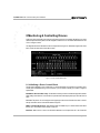
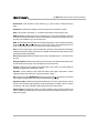
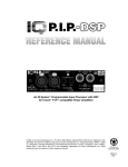
2.1 Basic Concepts
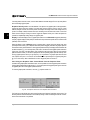
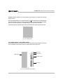
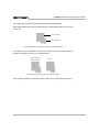
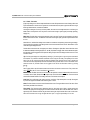
Turbo provides two methods of monitoring and controlling an IQ System: 1) using standard text screens or 2)
using custom graphics plates that you create. Each has unique advantages. After you have used Turbo to
configure the IQ System, you can then save all the system’s settings and all the graphics plates to a dataframe®
file on the computer’s hard drive or a floppy disk. If your audio system is like most, you will probably need more
than one configuration, one for each type of event it will serve. By saving each of these configurations to a
dataframe file, you can create a collection of dataframe files that enable you to quickly reconfigure your IQ
System. Simply “engage” the appropriate dataframe file whenever you want to reuse the configuration stored
within it.
Text Screen
Graphics Plate
Fig. 2.1 Sample Text Screen and Graphics Plate
Page 17
2
US
IQ–MSD Turbo 1.4 Advanced IQ System Software
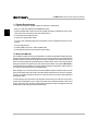
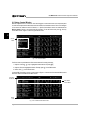
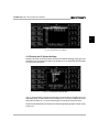
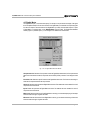
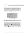
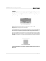
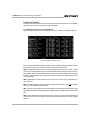
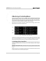
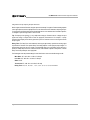
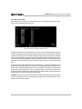
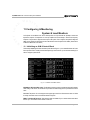
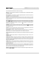
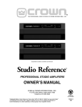
2.1.1 Text Screens
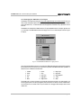
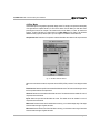
Several different types of text screens are available including Control Panel screens, Control Block screens,
Display screens and Sub-block screens. The Control Panel screens contain general controls that pertain to
the overall operation of Turbo such as serial port and baud rate settings. The main Control Panel screen is shown
below in Figure 2.2 and is described in detail in Section 2.4 later in this manual.
2
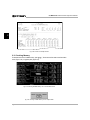
Fig. 2.2 The Main Control Panel Screen
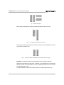
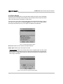
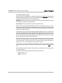
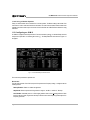
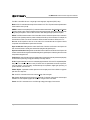
The remaining text screens are related to specific IQ components. They are described in detail in the Sections
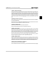
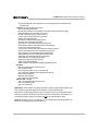
devoted to specific IQ components later in this manual. The Control Block screen is the most common text
screen in Turbo. It is the first interactive screen you see when you first run Turbo. Control Block screens contain
individual control blocks. Each IQ component has a single control block and most Control Block screens display
four control blocks at a time as is shown below in the amplifier Control Block screen in Figure 2.3:
One Control Block
Fig. 2.3 An Amplifier Control Block Screen
Page 18
IQ–MSD Turbo 1.4 Advanced IQ System Software
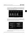
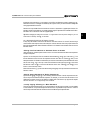
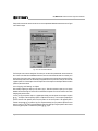
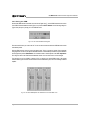
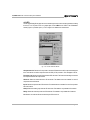
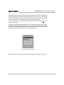
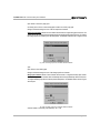
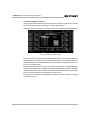
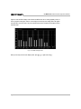
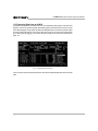
Some IQ components also have one or more Display screens. A prominent feature of Display screens is their
bar graph displays of signal levels. Amplifiers have two Display screens, a 6-bar and 8-bar Display screen. The
amplifier Display screens show both the input and output audio signal levels for each input channel of the IQ P.I.P.
Note: Only Crown P.I.P.-compatible amplifiers with an IQ P.I.P. can be controlled or monitored by the IQ System.
A 6-bar amplifier Display screen is shown below in Figure 2.4:
2
Fig. 2.4 A 6-Bar Amplifier Display Screen
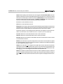
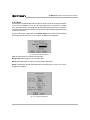
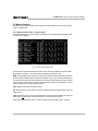
Finally, some of the more advanced IQ components also have one or more Sub-block screens. Sub-block
screens contain a collection of controls that are used to configure automatic functions like signal compression or
limiting, auto standby, automatic mic mixing, etc. An amplifier Sub-block screen is shown below in Figure 2.5. Only
amplifiers with IQ P.I.P.s having SmartAmp™ features have a Sub-block screen.
Fig. 2.5 An Amplifier Sub-block Screen
The biggest advantage of text screens is the ability to quickly set the parameters of many IQ components without
the need for custom-designed controls.
Page 19
IQ–MSD Turbo 1.4 Advanced IQ System Software
2
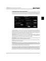
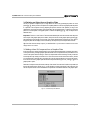
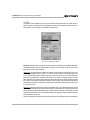
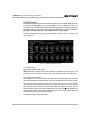
2.1.2 Graphics Plates
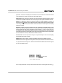
A graphics plate is a graphic screen in which custom objects can be designed and stored to create attractive
operator screens for your IQ System. It may sound scary but it is actually very easy to create a graphics plate and
it gives you tremendous power over your system because you decide what controls are available and in many
cases what operating range the controls have. In addition, you can cause Turbo to display a graphics plate rather
than a text screen when the program starts up, making the program that much friendlier for your operators. A
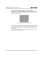
sample graphics plate which was made from a combination of preconfigured graphic display modules (GDMs)
and custom objects is shown in Figure 2.6 below:
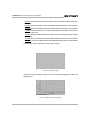
Fig. 2.6 A Sample Graphics Plate
The primary purpose of graphics plates is to provide operators with an attractive graphical interface that makes the
system easy to use and control. Well designed graphics plates can be very intuitive, keeping operator training time
to a minimum. You can create as many graphics plates as your computer’s memory and storage space allow. And
you can create buttons on them that allow the operator to jump from one graphics plate to another. You can even
create graphics plates with instructions to serve as “help” screens for new operators.
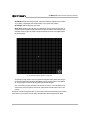
The graphics plate in Figure 2.6 was created on a PC that provided only standard VGA graphics. This means that
the graphics plate has a resolution of 640×480 pixels. However, if your computer has a compatible SVGA or
XVGA graphics adapter, you can set Turbo to use a higher resolution such as 800×600 (SVGA), 1024×768
(XVGA) or even 1280×1024 pixels. This will give you much more room to create elaborate graphics plates with
many controls. Section 3 later in this manual will describe graphics plates in much greater detail.
Page 20
IQ–MSD Turbo 1.4 Advanced IQ System Software
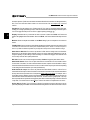
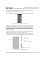
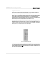
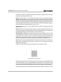
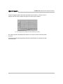
2.1.3 Perspective
Figure 2.7 might help put some of the text screens and the graphics plates in perspective. It shows the relationship
between control blocks, sub-blocks and graphics plates.
2
Graphics Plate Superset
Control Block
Control Block
Control Block
Control Block
Device
Menu
Control Block Display Now
Control Block Display Now
Control Block Display Now
Control Block Display Now
ASA
Sub-block
A single dataframe file contains
the control block and sub-block
settings for all the IQ components
in the system as well as all
custom graphics plates.
DATAFRAME
FILE
Fig. 2.7 Putting Text Screens and Graphics Plates into Perspective
Notice that the control blocks, located in the center of the frame, form the bedrock of the software. Below them are
the sub-blocks which expand to cover the automation functions of those IQ components that have them. The IQ
System can be configured entirely from the control block and sub-block text screens. At the top of the frame are the
graphics plates which serve as a user interface layer. Because you can determine which controls are available
on each graphics plate, you can shield operators from the complexity of the system.
When you save an IQ System setup to disk with the Turbo software, you create a dataframe file. A single
dataframe file will store all the system settings and all the graphics plates you created for that setup. Figure 2.7
depicts dataframe files as frames in a movie film. You “engage” dataframes to change the configuration of your
audio system much the same way that frames of a movie change the action in the film.
Page 21
IQ–MSD Turbo 1.4 Advanced IQ System Software
2.2 Starting the Program
Before running Turbo, first get a DOS prompt on your computer and then switch to the hard drive and directory
where Turbo is stored. For example, if Turbo is stored in the “turbo” directory, use the change directory (cd)
command as follows: cd \turbo.
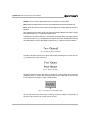
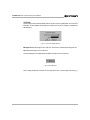
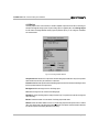
To start Turbo, type: turbo14. After a brief delay, the computer should display the title screen shown below
in Figure 2.8.
2
Fig. 2.8 The Turbo Title Screen
Note: Turbo may not be compatible with some terminate-and-stay-resident (TSR) programs, such as screen
savers and antivirus software. We recommend that all TSRs are disabled before running Turbo.
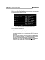
2.2.1 Optional Command Line Parameters
Four optional command line parameters (or switches) are available to control the way Turbo initializes. For
example, c:\turbo14 /d causes Turbo to omit displaying the title screen when it loads. The command
line parameters are listed next:
/d
Causes Turbo to omit its title screen when it loads.
/f file name
Instructs Turbo to load and engage the specified dataframe file. For example, type turbo /
fnormal.diq to run Turbo and engage the dataframe whose file name is “normal.” It is not
necessary to type the DIQ extension. Do NOT type a space between the “/f” and the file name.
/s
Directs Turbo to create a DPMI swap file when it loads. This swap file can enable Turbo to
run when the computer does not have much memory. Use this switch only when low
memory causes Turbo to run erratically.
Page 22
IQ–MSD Turbo 1.4 Advanced IQ System Software
/v
Causes Turbo to use a default VESA-compatible graphics driver. Turbo is usually able to
identify the computer’s graphics controller and use it for optimum graphics performance. Use
this switch only if Turbo is unable to identify or use the graphics controller in your computer.
2.3 Establishing Communication
After the title screen has been displayed for a few seconds, it fades and the computer automatically attempts to
establish communication with an IQ interface and, if an interface was found, initiate a roll call. Figures 2.9 and 2.10
show the messages that may result if Turbo has trouble finding or communicating with an IQ interface:
Fig. 2.9 No Interface Found Message
Fig. 2.10 Looking for Interface Message
In Figure 2.9, Turbo was unable to detect a CTS (Clear To Send) signal from the IQ interface. It then assumes that
no interface is present or that the interface is not properly connected. In Figure 2.10, Turbo thinks it found an IQ
interface and tries to communicate but cannot.
Page 23
2
IQ–MSD Turbo 1.4 Advanced IQ System Software
It then assumes that the baud rate is not set properly and it tries to automatically detect the baud rate of the interface
and configure the host computer with the same baud rate. It assumes that the interface is turned off or improperly
connected if it fails to determine the baud rate.
Once communication has been established with the IQ interface, Turbo begins a roll call. During a roll call, Turbo
conducts a poll to identify the Crown Bus loops present and to establish communication with all IQ components. As
the roll call progresses, the screen displays the loops and devices responding to the poll.
2
During the roll call, Turbo also determines the settings of all IQ components and stores them into memory. It then
enters the settings into the appropriate control blocks and, when appropriate, sub-blocks. The screen in Figure
2.11 shows the typical results of a successful roll call. Notice that the screen indicates the type of interface that was
found—in this example, an IQ Interface 2. The lower section of the screen includes a tally of the number and type
of devices that responded to the roll call.
Fig. 2.11 A Typical Roll Call
A roll call can be stopped at any time by pressing q or X. Pressing the “Space Bar” will force the roll call to
advance to the next loop.
There are several parameters (system controls) that control both communication with the IQ interface and the way
a roll call works. These parameters are located on the Control Panel screen (discussed next).
Page 24
IQ–MSD Turbo 1.4 Advanced IQ System Software
2.4 Setting Turbo’s System Parameters
The general system controls of Turbo are located on the Control Panel screen shown in Figure 2.12. It is often
necessary to make changes to these settings the first time you run Turbo because the default settings may not be
correct for your system’s host computer. From a Control Block screen, press ) to go to the Control Panel screen.
2
Fig. 2.12 Control Panel Screen
Use T or S+T to move the focus from one control to the next. (T advances to the next control and
S+T returns to the previous control.) Use the “Space Bar” to change an on/off control such as the Port Active
control or activate a button control like the Roll Call button. Use Q R to change the selection of an either/or control
like the Display control. Many of these controls can also be set with a mouse ({).
Serial Port: Sets the serial or com port that Turbo will use to communicate with an IQ interface. This is usually
serial port 2 because most computers have a serial mouse connected to serial port 1. Changing the serial port
number will automatically cause a new base address and interrupt to be selected.
Base Address: Sets the base address in memory where Turbo must access the serial port. Normally you can
accept the default. If necessary, a different base address can be entered.
Interrupt: Sets the system interrupt used by the serial port. Normally you can accept the default. If necessary,
a different interrupt number can be entered.
Baud Rate: Sets the first speed that Turbo will attempt to use to communicate with the IQ interface. However,
Turbo has an “auto baud detect” feature and will automatically change the baud rate of the host computer if it fails
to communicate with the IQ interface at the baud rate you selected. In this way, the baud rate control also serves
as a baud rate indicator, showing the baud rate currently being used.
The baud rate of the host computer must match the baud rate of the IQ interface. Although some IQ interfaces can
support speeds as high as 38400 baud, some serial cables and some host computers cannot go this fast. The
device with the lowest maximum baud rate will set the maximum possible baud rate for your system. For example,
if the serial port of your host computer can only go as high as 9600 baud, you will have to set the IQ interface to
Page 25
IQ–MSD Turbo 1.4 Advanced IQ System Software
this slower speed also. (Refer to the manual that came with the IQ interface for instructions on setting its baud rate.)
Note: Turbo’s auto baud detect feature enables it to set the baud rate of the host computer only—not the IQ
interface.
Port Active: Turns the serial port on or off. When turned off, Turbo does not communicate with the IQ System,
enabling you to change system settings or edit or create new dataframe files without affecting the actual IQ System.
You can also toggle the serial port on and off from a graphics plate by pressing A+p.
2
Display: Determines the way a control will look when it is turned on. When set to Solid, on/off controls will
appear to be highlighted with solid bold letters. When set to Blink, on/off controls will blink when they are turned
on.
Monitor: Should normally be set to Color. Use the Mono setting if your host computer has a monochrome
monitor.
Fast Roll Call: Causes roll calls to run at the fastest possible speed. Most IQ components can respond to a fast
roll call but a few of the older ones cannot (such as MPX-6 mixers prior to version 1.3 and IQ–P.I.P.s prior to
version 1.4). Make sure that all components in your IQ System can respond to a fast roll call before using it.
Auto ASA on Roll Call: This control is only relevant if a DRN–16 drone is being used as an IQ interface.
When turned on, the ASA (Auto System Activate) control on the drone is temporarily disabled during a roll call,
during the uploading of system settings or when the settings in a dataframe are engaged. This allows the drone
to focus solely on the roll call for optimal performance.
Roll Call: Causes a new roll call to be begin immediately. Caution: All graphics plates will be cleared.
Auto Break Detect: Causes Turbo to report when breaks in communication occur and to initiate a search
for the location of the break. The serial connection between the host computer and the IQ interface is always
monitored when Auto Break Detect is turned on. However, not all Crown Bus loops may be monitored, depending
on the setting of the Auto Search All Loops control (described next).
Auto Search All Loops: This control is only relevant if Auto Break Detect is turned on. It forces Turbo to
include all Crown Bus loops in its search for breaks in communication. If it is turned off, the auto break detect feature
will only search those loops which have IQ components that are visible on the screen. For example, when a
Control Block screen is displayed, only the loops represented in the visible control blocks will be included in the
auto break detect search if Auto Search All Loops is turned off. The same is true of a graphics plate—only loops
with components that are represented on the graphics plate will be monitored. By turning on the Auto Search All
Loops switch, Turbo will be forced to check all loops—even the ones that are not represented on the screen.
Online Search: Enables Turbo to respond to a missing IQ component (one that was previously on line) by
periodically attempting to reestablish communication with it and bring it back on line. After the unit is back on line, its
Page 26
IQ–MSD Turbo 1.4 Advanced IQ System Software
current settings will be uploaded and its control block and sub-blocks updated. Note: This feature does not enable
Turbo to find new IQ components that do not yet have a control block. To add new components you must either
run a roll call or manually create a control block for each new component.
Search Loop #: Can be used to locate a break in a particular Crown Bus loop. To use this function, first enter
the Search Loop number. Then activate the Search button (shortcut: press A+s). If there is a break in the loop,
Turbo will display its approximate location.
Search: Causes Turbo to immediately begin searching the specified Crown Bus loop for breaks in communication. The loop is specified by the preceding Search Loop # control.
Solo Function Enabled: Activates the solo feature so the Solo controls located on individual amplifier
control blocks are enabled. If this control is turned off, the amplifier Solo controls will not work. It provides a way to
have global control over the solo feature.
Emergency Mute: Activates the emergency mute feature which allows an operator to quickly mute certain
IQ components by rapidly pressing the “Space Bar” five or more times. The IQ components affected by the
emergency mute feature are all the mixers (MPX-6, SMX-6, AMB-5) and amplifiers with IQ P.I.P.s (including IQ2
P.I.P.s).
Remote Emergency Mute: Activates a feature whereby an external logic signal sensed by an AUX port
of an IQ component is used to trigger an emergency mute.
Address: Specifies the Crown Bus loop, component type and IQ address of the IQ component whose AUX port
input will be monitored for the remote emergency mute feature. Use the following procedure to determine the
address:
1 Begin with “L” followed by the loop number of the IQ component.
2 Use one of the following three-letter mnemonics for the component type:
AMP Amplifier with IQ–P.I.P.–AP (version 1.45 or later)
MPX MPX-6 mixer
SMX SMX-6 mixer
AMB AMB-5 mixer
MRX MRX-24 or MRX-12 matrixer
PSI Pocket Serial Interface
SLM SLM-8 system and load monitor
3 Specify the IQ address of the component after the component type.
Notes: Case does not matter. Commas and spaces are ignored and can be added to improve readability.
Here are a couple of examples:
L1 SMX5
L3, AMP 1
SMX Max Gain Auto Compensation: This control is only relevant when programming an analog
input of a DRN-16 drone to control the Max Gain of an SMX-6 mixer. A better way to accomplish this is to turn on
the Max Gain to Track Control Block and Control Block Override switches in the first SMX sub-block and then
assign a drone pot to an SMX-6 attenuator. (Please contact Crown’s Technical Support Group for more information.)
Page 27
2
IQ–MSD Turbo 1.4 Advanced IQ System Software
System AUX: This control opens the System AUX Setup screen, a second type of Control Panel screen. The
system AUX feature allows an external logic signal sensed by the AUX port of an IQ component to cause the IQ
System settings to be either loaded (engaged) from a specified dataframe file or saved to a specified dataframe
file.
The System AUX Setup screen is shown below in Figure 2.13. The keyboard shortcut to it from the main Control
Panel screen is A+a.
2
Fig. 2.13 System AUX Setup Screen
Up to 16 different AUX ports can be monitored at the same time and each one can load or save the settings from/
to a different dataframe file. Notice that three parameters are used to define a single System AUX function: Monitor,
Action and Dataframe. Use Q R Z Y to select the function you want to enter or edit (T does not work in this
screen).
The monitor parameter identifies which AUX port is to be monitored. Use the following procedure to describe
it:
1 Begin with “L” followed by the loop number of the IQ component.
2 Use one of the following three-letter mnemonics for the component type:
AMP Amplifier with IQ–P.I.P.–AP (version 1.45 or later)
MPX MPX-6 mixer
SMX SMX-6 mixer
AMB AMB-5 mixer
MRX MRX-24 or MRX-12 matrixer
DRN DRN-16 drone
PSI Pocket Serial Interface
SLM SLM-8 system and load monitor
Page 28
IQ–MSD Turbo 1.4 Advanced IQ System Software
3 Specify the IQ address of the component after the component type.
4 For a drone, specify a drone input with “IN” followed by the input number (1-16).
Notes: Case does not matter. Commas and spaces are ignored and can be added to improve readability.
Here are some examples:
L1 SMX5
L3, AMP 1
L1, DRN 24, IN 5
2
The action parameter identifies what action will be taken with the specified dataframe file. The choices are
None, Load and Save. (The action is taken when the AUX input changes from a logic low to a logic high.) After
selecting the action field, use the “Space Bar” to toggle between the available choices.
The dataframe parameter identifies the dataframe file name that you want to load or save.
After you have finished with this screen, press X to return to the main Control Panel screen.
The following controls refer again to the main Control Panel screen (Figure 2.12).
Printer Port: Sets the destination for printed reports of the system settings. The reports can be sent to a printer
via a parallel port (LPT1 or LPT2) or saved to a file. To create a report, press % from a Control Block screen.
File Name: Specifies the file name to be used if the Printer Port option is set to send the report to a file. The
report is written as a text file that can be viewed and edited by most text editors or wordprocessing programs.
Note: There is not a default extension, so you should enter an appropriate extension (like TXT).
Ok: Closes the main Control Panel screen and returns you to the previous Control Block screen. The keyboard
shortcut to exit the Control Panel screen is either A+k or X.
All control panel settings are saved to a TURBO.INI file when you leave the Control Panel screen. Note: Older
version of Turbo saved the control panel configuration to a CROWN.DTA file. It can be deleted after a
TURBO.INI file has been created.
Help: This control opens a help box which lists a brief description of each system control on the Control Panel
screen. The keyboard shortcut is either A+h or !.
Page 29
IQ–MSD Turbo 1.4 Advanced IQ System Software
2.5 Using Control Blocks
Most IQ components have a control block. As its name suggests, a control block serves as a ready-made place
to control an IQ component. All control blocks can be accessed from a Control Block screen. This is one of the types
of text screens we referred to earlier in Section 2.1.1. Specific Control Block screens are selected with the
Device menu. (Device is synonymous with IQ component.) To use the Device menu, press ! from any
Control Block screen. Figure 2.14 shows a typical Device menu.
2
Device
Menu
Fig. 2.14 The Device Menu
The Device menu is quite flexible and offers several methods for making a selection:
1 Keyboard: Use the Z Y keys to highlight the desired device and press E.
2 Keyboard: Press the highlighted character. Example, press s for the SMX-6 mixer.
3 Mouse: Click ({) on the desired device.
A sample SMX Control Block screen is shown below in Figure 2.15. Notice that four individual SMX-6 control
blocks are visible on the SMX Control Block screen.
Command
& Title Bar
One SMX-6
Control Block
Status
Lines
Fig. 2.15 An SMX Control Block Screen
Page 30
IQ–MSD Turbo 1.4 Advanced IQ System Software
A Command & Title Bar is located at the top of the Control Block screen. It lists the function keys (!@%())
that are available from the Control Block screen and, in the center, the IQ components represented in the control
blocks (SMX). At the bottom of the control block screen are two status lines which display the Offset number and
the current dataframe file name.
The offset number is the number of the currently selected control block and it helps you keep track of your
location in systems with many IQ components. The control blocks are numbered from top to bottom, beginning with
1 (one) at the top. Suppose, for example that your IQ System has ten SMX-6 mixers. Each one will be given its
own control block so your system will have 1-10 control blocks. Since only four of them can be viewed at the same
time in the Control Block screen, Turbo will allow you to scroll through them with O N. When you do this, the
offset number tells you which control block has the current focus of the system. If you scroll down to the seventh
control block, the offset number will be seven. In the example in Figure 2.15, the offset number is one because the
first control block has the focus.
If a dataframe file has been engaged or saved, its name will be listed at the very bottom of the screen. In Figure
2.15, dataframe file SETUP-1 is listed.
Occasionally you may also see other items listed on one of the status lines. For example, some screens will list “Esc
- Exit” in the far right corner to let you know that you can exit the screen by pressing the X key.
The control blocks of some, but not all, IQ components are also available from a graphics plate. Figure 2.16 shows
a graphics plate version of the same SMX-6 control block that is highlighted in Figure 2.15. It is accessed by
double-clicking ({) on the GDM (graphics display module) of an IQ component.
Although both the text screen and graphics plate versions of a control block appear to have many of the same
controls, the graphics plate version is slightly more limited than the text version. For instance, the graphics plate
version only allows you to display one control block at a time. In addition, the ASA (Auto System Activate) control
can only be turned on and off—you cannot use it to access the sub-blocks where the automation features are
Fig. 2.16 An SMX-6 Control Block from a Graphics Plate
configured. To access the automation features from a graphics plate you would need to create your own custom
sub-block with the various control objects in the graphics plate Toolbox. (Sub-blocks are discussed in Section 2.6
and graphics plates are discussed in Sections 2.8, 3 and 4.)
Page 31
2
IQ–MSD Turbo 1.4 Advanced IQ System Software
2.5.1 The Parts of a Control Block
Now lets focus on just one control block and see how it is put together. Notice in Figure 2.15 that each control block
forms a horizontal row on the screen, four text lines in height. Figure 2.17 shows a single control block:
Information
Controls
2
Fig. 2.17 A Closer Look at a Control Block
The left side of the control block consists of information about the IQ component it controls. The IQ address and
Crown Bus loop number are listed at the top and are automatically entered as part of the roll call. They can also
be manually entered, making it possible to prepare dataframe files while the host computer is disconnected from
an IQ System. “On Line” is displayed in the upper right corner of the information area when an active IQ
component has been detected by Turbo. Below the IQ address and Crown Bus loop number are three
information lines where you can enter the model, location and purpose of the IQ component. Most control blocks
allow you to type anything you want here. Some control blocks, like the amplifier control blocks, require you to
select a model from a list.
The right side of the control block contains the controls. The controls serve a sort of dual purpose: they can be
used to send a command to an IQ component and they can be used to display the current setting of an IQ
component. (C+u causes Turbo to upload and display the current settings of all IQ components in the system.)
Some IQ components also have special dedicated monitoring features located in this section of the control block
(such as input signal level indicators). Because the controls vary widely from one type of IQ component to the next,
they will not be described in detail here. The controls and monitoring features of specific IQ components are
addressed later in this manual.
2.5.2 Navigating Control Blocks & Setting Controls
A few special techniques are required to successfully use the Control Block screens. For example, the focus
(cursor) is normally confined to a single control block at a time. How do you move it from one control block to
another? How do you add a new control block for an off line IQ component when all visible control blocks are
already being used? This section will answer these and other questions relating to the use of control blocks.
• Moving from One Control Block to Another
Keyboard: Use O or N to move up or down from one control block to the next. The Offset number at the bottom
of the screen will indicate the number of the selected control block. Press “Home” } to move to the first control
block. Press “End” ~ to move to the last control block.
Mouse: Click the middle mouse button ({) and drag the mouse up and down to move through the control blocks.
Page 32
IQ–MSD Turbo 1.4 Advanced IQ System Software
• Adding a New Control Block
Keyboard: Control blocks are automatically created for all on line IQ components during a roll call. In addition, new
control blocks can be manually added for off line IQ components. This is easy to do if an empty control block is
visible in the Control Block screen. Use O or N to select it and then enter the IQ address and Crown Bus loop
number of the off line IQ component. How do you manually add a control block if no empty ones are visible in the
Control Block screen? First, press N until you reach the last control block. Then press N one more time to
create one new control block. You can also press S+N to force Turbo to add more than one new control
block.
• Selecting a Control or Text Line
Keyboard: Use Z Y Q R to position the cursor on the desired control or text line. When the line is highlighted,
it is selected and ready for input.
Mouse: Move the mouse ({) without clicking or dragging until the cursor is on top of the desired control or text line.
When the control or text line is highlighted, it is selected and ready for input.
• Setting an On/Off Control
Keyboard: Select the desired on/off control and press the “Space Bar”.
Mouse: First select the desired on/off control. Then click the left mouse button ({).
• Setting a Level Control
Keyboard: There are two ways to set a level control. You can enter the value directly or you can increment/
decrement the value in steps (usually ½ dB steps). Begin by selecting the desired level control. Then you can
enter the value directly by typing the number you want and pressing E to engage the new level. (Precede
negative numbers with the negative key.) Or you can press S+Z to increment or S+Y to decrement the
level. Note: Fractions cannot be entered directly. Use the increment/decrement method for fractions.
Mouse: First select the desired level control. Then, press and hold S while moving the mouse ({) upward to
increment and downward to decrement. Do not click or drag while moving the mouse.
• Setting a Range Control
Keyboard: A “range” control let’s you select from a list of preset choices. For example, the dual/mono control in an
amplifier control block allows the following settings to be selected: DUAL, BRID and PARA. These controls function
very similarly to an on/off control. To set them, first select the control then press the “Space Bar” to advance the
selection from one value to the next. The selection will advance to the first choice after passing the last one.
• Moving from a Control Block to a Sub-block
Keyboard: Select the ASA control and press Y or E.
Mouse: With the ASA control selected, move the mouse ({) in a downward direction without clicking or dragging.
Page 33
2
IQ–MSD Turbo 1.4 Advanced IQ System Software
2.6 Using Sub-blocks
Some, but not all, IQ components have one or more sub-blocks. As their name suggests, sub-blocks are
organized “under” control blocks. They allow the user to delve deeper into the controls of a IQ component. Subblocks contain the controls that configure the automation features of the more advanced IQ components. A single
sub-block contains the controls for one function. Some Sub-block screens contain more than one sub-block. All
Sub-block screens are accessed from a parent control block with the ASA (Auto System Activate) control.
2
The ASA control serves a dual purpose. First, by turning it on and off, you enable or disable all functions in the subblocks. Second, it is used to gain access to the Sub-block screen(s). This is accomplished by pressing E or
Y when the ASA control is selected. Mouse users can simply move the mouse down ({) from the ASA control
without clicking.
The next two illustrations show some typical Sub-block screens.
Notice in both Figure 2.18 and 2.19 that the status of the ASA control is indicated at the top of the screen (top left on
the amplifier Sub-block screen and top right on the mixer Sub-block screen). Although the actual ASA control is
Fig. 2.18 An Amplifier Sub-block Screen for an IQ–P.I.P.–SMT
Fig. 2.19 The First of Four SMX-6 Mixer Sub-block Screens
Page 34
IQ–MSD Turbo 1.4 Advanced IQ System Software
located back in the control block, you can toggle it on and off from the Sub-block screens by pressing A+a.
When ASA is turned on, all changes are executed by the IQ System as they are made. Sub-block changes are
not engaged while ASA is turned off.
Sub-blocks are only available from text control blocks—there is no equivalent on a graphics plate. However, if is
possible to create custom sub-blocks on a graphics plate by using the objects which are available in the Toolbox.
See Section 2.8 for a discussion of the use of graphics plates.
Tip: Before changing the settings of a sub-block, it is a good idea to save the previous settings so you can
restore them, if necessary. Press ( to save them.
2.6.1 Navigating Sub-blocks & Setting Controls
In many ways, the sub-block controls work the same as control block controls. You set on/off, level and range
controls with the same keyboard and mouse techniques. However, sub-blocks have many unique features and
this section will describe them. Please refer back to Section 2.5.2 for details of common features such as how to set
individual controls.
• Moving from One Sub-block or Sub-block Screen to Another
Unlike control blocks, sub-blocks place no limits on cursor or mouse movement because all the controls pertain to
a single IQ component.
Keyboard: You can freely move from one sub-block to the next with the Z and Y keys or the mouse ({). This
includes Sub-block screens for those IQ components that have more than one. Pressing Y when you are
already at the bottom of a Sub-block screen will send you to the next control at the top of the next Sub-block screen
and visa versa. Use Z or Y to move up or down from one Sub-block screen to the next. Use } to move to the
first Sub-block screen. Use ~ to move to the last Sub-block screen. Note: “Home” } and “End” ~ do not
function in drone Sub-block screens.
Mouse: Move the mouse ({) up and down without clicking or dragging to move up and down the sub-blocks and
Sub-block screens.
• Moving Among Sub-blocks of Similar Components
Keyboard: Press C+Q and C+R to move sideways from the sub-block of one IQ component to the next.
This can only be done between similar IQ components. For example, you can move from the sub-block of one
SMX-6 mixer to another, but not from an SMX-6 to an AMB-5. Note: This feature is only supported for amplifier
and mixer sub-blocks. It is not supported by drone sub-blocks.
• Locally Copying & Pasting in a Mixer Sub-block
The local copy and paste feature allows you to copy the setting of one input control to another. It is only available
for mixer sub-blocks, it only works with adjacent columns and it is only available for input controls. It cannot be
used for output controls like the Limit Threshold control of the SMX-6 Output Compress/Limiter.
Page 35
2
IQ–MSD Turbo 1.4 Advanced IQ System Software
Keyboard: Select the desired control setting. Then, press S+Q or S+R to copy the setting horizontally
across the sub-block. For example, the –5 dB Max Gain setting was copied from Input 2, Channel 1 in Figure 2.19
to the other inputs by pressing S+R.
Mouse: First select the desired control setting. Then, press and hold S and move the mouse ({) to the left or
right to copy the values horizontally across the sub-block.
2
• Globally Copying & Pasting Between IQ Components
The global copy and paste function copies all the settings of all the sub-blocks of one IQ component to the subblocks of another identical IQ component. This feature is only available for amplifier and mixer sub-blocks.
Keyboard: First press A+c to copy the sub-block settings of the present IQ component into memory. This
causes “Copy” to appear in the upper right corner of the screen below the IQ address and loop number. Next,
press C+Q or C+R to move to the Sub-block screen of the destination IQ component. (Use the IQ address
and loop number in the upper right corner of the screen to locate the component.) Finally, press A+v to paste
the settings into the sub-blocks of the destination IQ component.
• Restore Default Settings to All the Sub-blocks of an IQ Component
Keyboard: Press A+x to restore all sub-block settings of the selected IQ component (except drones). The
settings of legacy IQ P.I.P.s and mixers will be changed to their minimum values. The settings of IQ2 components
will be restored to their factory default values.
• Moving from a Sub-block Back to a Control Block
Keyboard: Press X from any sub-block or press O from the first sub-block or press } then O from any
sub-block. Note: “Home” } does not function in drone sub-blocks.
Mouse: Click the right mouse button ({). You can also move the mouse in an upward direction without clicking or
dragging until the control block is displayed.
Tip: Press A+! from any sub-block to open a help window listing many of the points in this section. A sample
Fig. 2.20 A Sample Sub-block Help Window
Page 36
IQ–MSD Turbo 1.4 Advanced IQ System Software
help windows from an amplifier DSP sub-block is shown below:
2.7 Activating Emergency Mute
During the course of configuring any sound system, mistakes can be made. An input can be turned up too loud,
resulting in runaway feedback between one or more microphones and loudspeakers. Although you can use the
IQ System to minimize these problems, it is not immune to “operator error.” This is why we added the emergency
mute feature. It allows you to quickly mute many of the IQ components from any Control Block screen, Sub-block
screen or graphics plate. To activate this feature, press and hold the “Space Bar” or tap it rapidly five or more times
until the audio is muted. Note: In order to use this feature, it must first be enabled on the Control Panel. Refer
to Section 2.4. The following IQ components will respond to an emergency mute: all mixers (MPX-6, SMX-6,
AMB-5) and amplifiers with legacy IQ P.I.P.s (IQ–P.I.P., IQ–P.I.P.–AP). Amplifiers with IQ2 P.I.P. will not respond.
When emergency mute has been activated, the following screen in Figure 2.21 will appear:
Fig. 2.21 The Emergency Mute Screen
The system will stay muted until it is re-engaged or until you change the controls that are used to mute (such as
the amplifier All Mute controls and the mixer Input gain controls). While the emergency mute function is active you
can return to the control blocks or graphics plate by pressing X to exit the Emergency Mute screen. Then make
changes to correct the problem. All changes will take effect immediately. After the problem has been corrected,
press C+e to re-engage the system and the settings in all control blocks, sub-blocks and graphics plates will
be resent to the IQ System.
If you prefer, you can also choose to load new settings from a dataframe file by pressing (. If you do, you will
not have to manually re-engage the system because the act of loading a dataframe file automatically causes the
system to engage the new settings.
Page 37
2
IQ–MSD Turbo 1.4 Advanced IQ System Software
2.8 Graphics Plates
Seldom are two audio systems used in the same way. Even the same audio system will probably be operated in
very different ways, depending on the nature of each event or the abilities of each operator. How would you like
to have a custom control panel for your system? Better yet, how would you like to have a custom control panel for
each type of event? Or a custom control panel for each operator? This section will show you how to accomplish
this with graphics plates.
2
A graphics plate is a graphic screen in which custom objects can be designed and stored to create attractive
operator screens for your IQ System. A wide variety of objects are available from the graphics plate Toolbox. For
example, the Toolbox has bar meter and LED objects that mimic the real thing. It also has “pots” that mimic level
controls and buttons that mimic a pushbutton. You use these prebuilt objects to construct control panels for your
system on one or more graphics plates. Figure 2.22 shows some of these objects and the Toolbox menu.
You have complete control to decide which controls your operators can access and, in many cases, what the
operating range of the controls will be. For example, you can create a “pot” for the input attenuator of Channel 1
of an IQ P.I.P.-equipped Crown amplifier and decide where it will be located on the screen, what its size and color
will be and what its maximum and minimum settings will be. Next you can create a bar meter to monitor its input
level. You decide whether or not the bar meter will have a “peak hold” feature and include a text legend.
Fig. 2.22 A Graphics Plate Under Construction
Page 38
IQ–MSD Turbo 1.4 Advanced IQ System Software
2.8.1 The Graphics Plate Control Block Screen
Graphics Plates are treated like IQ components because each one has a control block. Use the Device menu
(!) to go to the graphics plate Control Block screen (shown below in Figure 2.23).
2
Fig. 2.23 The Graphics Plate Control Block Screen
Like most control blocks, the graphics plate control blocks are divided into two parts. On the left is the information
area and on the right are the controls.
Number: The Number parameter is the first item in the information side of the control block. It provides a
convenient way to differentiate one graphics plate from another. Enter any number between 1 and 999. Three
blank lines are available below the Number parameter for labelling the graphics plate or for relevant notes.
Trigger: Determines whether or not the associated graphics plate will be automatically displayed when a
dataframe file is engaged. This is a great feature for hiding the complexity of Turbo from your operators. All they
see is the controls you give them on the graphics plate. When Trigger is turned on, the text Control Block screens
will be bypassed and the graphics plate will be displayed instead. When Trigger is turned off, Turbo will stay in the
Control Block screens after a dataframe file is engaged. The Trigger of only one graphics plate should be turned
on at a time. If more then one is turned on, the graphics plate having the lowest Offset will be displayed. Note: If
you turn on a Trigger (or change any parameter), be sure to save the dataframe file by pressing ( so the
change(s) will not be lost.
Display Now: Causes the associated graphics plate to be displayed immediately. There are two display
modes: Selected and Memory. The display mode is controlled by the Display control on the last line of the control
block. After the graphics plate is displayed, you can return to the text Control Block screen by pressing X, !
or clicking the right mouse button ({).
Control Security Lock: Locks the operation of all control objects on the graphics plate so they cannot be
used to make changes to the IQ System. In addition, the graphics plate version of the control blocks cannot be
accessed when Control Security Lock is turned on. However, this does not prevent graphic controls and objects
Page 39
IQ–MSD Turbo 1.4 Advanced IQ System Software
from being edited—their size, location, color and other attributes can still be changed. This is a very handy feature
when constructing a graphics plate.
2
Graphics Security Lock: Locks the attributes of all objects on the graphics plate so their appearance,
location and function cannot be changed. This means they cannot be resized, moved or have any of their
attributes changed. However, this does not prevent control objects from being used to make changes to the IQ
System. For example, a button can still be used to turn something on and off, but the size, location or color of the
button cannot be changed. Turning on both the Trigger and Graphics Security Lock controls will prevent an
operator from haphazardly making changes to a graphics plate.
Display: Controls the display mode of a graphics plate. When it is set to Selected, the graphics plate will try
to display a graphic display module (GDM) for all relevant IQ components in the system whose control block Sel
(Selected) control is turned on.
Setting the Display control to Memory causes a graphics plate to display only those objects which were
previously stored in memory (or in a dataframe file if it has just been engaged). More than one graphics plate can
be stored into memory at the same time. To store a graphics plate into memory, first display it, then double click with
the left mouse button ({) on an unused portion of the screen. This will summon the graphics plate control block
(Figure 2.24). Then click on the Store button. (This is explained in the next section.) When you exit a graphics
plate that has been edited, you will also be prompted to store the updated graphics plate into memory. Note:
Storing a graphics plate into memory is only temporary—it is not permanent. The graphics plate will be lost if the
host computer loses power or is turned off. Use the dataframe file to permanently store a graphics plate (press
( from a control block). When a dataframe file is saved, all graphics plates are saved in it.
2.8.2 Using the Graphics Plate Control Block from the Graphics Plate
In addition to the graphics plate Control Block screen, it is also possible to access the graphics plate control block
from the graphics plate itself by double-clicking ({) on an unused portion of the graphics plate. Figure 2.24 shows
the graphics plate version of the graphics plate control block.
To close the graphics plate control block, click once ({) anywhere outside of it.
Fig. 2.24 The Graphics Plate Version of the Graphics Plate Control Block
The “Data” area on the left side is the same as the information area of the text Control Block screen version. The
Number parameter and text field below it can be edited by clicking on them and entering the new text. However,
the rest of the control block is very different.
Page 40
IQ–MSD Turbo 1.4 Advanced IQ System Software
The Trigger, Control Lock, Graphics Lock and Display controls are not operational in this control block. They are
intended only to indicate the current settings—you must return to the Control Block screen to change them. The
other controls are fully operational and are explained below.
Store: Stores the current graphics plate into memory (the volatile memory or RAM of the host computer) where
the rest of the IQ System’s settings are kept during operation. Storing a graphics plate into memory is the first step
in saving it. The second step is to save all the system settings and all graphics plates in memory to the computer’s
hard drive in a dataframe file. This is done by pressing (. IMPORTANT: If you made changes to a graphics
plate and then exit it without storing it in memory, all of the changes will be lost.
The number of graphics plates which can be stored into memory is determined by the complexity of the graphics
plates and the amount of available memory in the host computer.
Restore: Restores the graphics plate to the last version that was stored into memory. This is a handy way to
undo changes that were made to a graphics plate since they were last stored.
Flush: Removes all objects except the Crown IQ logo from the graphics plate. You can think of this as a “clear”
button which clears the graphics plate. Note: Flushing a graphics plate does not remove it from memory (if it was
previously stored there). If you exit the graphics plate without saving changes all of the flushed objects will
reappear if you return to the graphics plate.
Peak Indicators: This control only affects the pre-built GDMs of legacy IQ P.I.P.s (such as the IQ–P.I.P. and
IQ–P.I.P.–AP). It causes the signal peak to persist for a fraction of a second when an audio input signal of a legacy
IQ P.I.P. is monitored with a pre-built GDM.
Screen Background / Variable Palette: There are two selectable colors, the background color of
the graphics plate and a custom color called the “variable palette” color. The variable palette color is available as
one of the color selections in the Attributes window of many objects. Click on the up/down arrows in the lower right
corner of the control block to select the Screen Background or Variable Palette color. Then use the up/down
arrows beside each primary color (red, green, blue) to mix a desired color.
Each primary color has a range of 0 to 255 with zero being none of the color and 255 being 100% of the color.
Setting all primary colors to 255 will produce white. Setting them all to 0 (zero) will produce black. When you mix
a custom color, you may want to record the level you used so you can reproduce the color again later on a
different graphics plate.
Page 41
2
IQ–MSD Turbo 1.4 Advanced IQ System Software
2.9 Saving and Loading Dataframe Files
All of the settings of the IQ System can be saved and later reloaded (engaged) with dataframe files. To save or
load a dataframe file, press ( to summon the File menu. As Figure 2.25 shows, there are three selections
on this menu:
2
Fig. 2.25 The File Menu
A. Save Dataframe as _____: Saves all system settings and graphics plates as a new dataframe file.
After pressing the E key, enter file name in the blank space provided. The file name can be only eight
characters long and is not case sensitive. Do not add an extension because “.DIQ” will be automatically
appended to the end of the file name. Press E again to create the new dataframe file.
B. Save Dataframe: Saves all system settings and all graphics plates to the current dataframe file. This
selection does not prompt for a file name. The settings and graphics plates in the dataframe file will be replaced with
the new ones. Use the first menu choice (Save Dataframe As...) and enter a new file name if you do not want to
overwrite an existing dataframe file.
Note: Any changes made to the system settings or graphics plates must be saved before exiting Turbo or they
will be lost.
C. Load Dataframe: Loads the system settings and graphics plates from an existing dataframe file. The
settings are automatically engaged after the they have been loaded.
Once E has been pressed, a window displaying a list of all available dataframe files will be displayed (see
Figure 2.26). Use Z Y to make a selection then press E again to load and engage the dataframe file.
Notice that this window also provides several additional features. The current path is listed at the very top of the
window (in the example in Figure 2.26 the path is “E:\TURBO14\*.*”. To move up the directory tree, select “..\”
and press E. To move to a different drive or directory, select the drive letter (example: “[C:]”) or directory name
and press E. To delete a file, select it and then press A+d. To sort the files by name press A+s.
Page 42
IQ–MSD Turbo 1.4 Advanced IQ System Software
2
Fig. 2.26 The Dataframe File List Window
2.10 Printing the IQ System Settings
All settings of all controls of most IQ components in the system can be printed by pressing % or C+p from any
Control Block screen. The following menu (Figure 2.27) will appear so you can select the type of IQ components
you want to include in the printout.
Fig. 2.27 The Print Select Components Menu
Use Z Y and the “space Bar” to select the component types to include in the printout. Press E when you are
ready to begin printing. The printout will be sent to the parallel port (LPT1 or LPT2) that is selected in the Control
Panel screen (see Section 2.4). You can also redirect the printout to a file with the Control Panel screen.
The printout is plain ASCII text which is formatted for 80 columns with appropriate page breaks. A sample is shown
in Figure 2.28.
Page 43
IQ–MSD Turbo 1.4 Advanced IQ System Software
2
Fig. 2.28 A Portion of a Sample Printout
2.11 Checking Memory
To determine the amount of available memory, press C+!. This can be used from either a text Control Block
screen (Figure 2.29) or a graphics plate (Figure 2.30).
Fig. 2.29 Checking Available Memory from a Control Block Screen
Fig. 2.30 Checking Available Memory from a Graphics Plate
Page 44
IQ–MSD Turbo 1.4 Advanced IQ System Software
DE
S
L
A
TE
I
P
G
N
CS
HI
3 Designing Graphics Plates
P
Fortunately you don’t have to be an artist to create an attractive graphics plate because we have included a wide
array of pre-made graphic objects which are easy to use. They are listed in the graphics plate Toolbox (see
Figure 2.22). We’ve also included a number of pre-configured objects for many IQ components. We call them
GDMs or Graphic Display Modules because they graphically display many of the monitor and control features of
our IQ components. Before we delve into the details of graphics plate design, let’s discuss a few general principals.
3.1 Overview
There are two things to consider before designing a graphics plate: its purpose and its intended user. You may
want to write down the purpose and then list all the things that it will need to carry out that purpose. The purpose
will determine which types of control and monitor objects will be required. It is important to consider the intended
user or operator in order to design a graphics plate that is as friendly and easy-to-use as possible for the operator.
What is the skill level of the operator? How much control should he or she be allowed to have over the system?
How will the graphics plate be used under various conditions—including emergencies? These questions are
important to designing a good graphics plate. Sometimes you will need to design more than one graphics plate for
an operator. They can be linked with system buttons that allow the operator to jump from one graphics plate to
another.
3.1.1 A Simple Example
Usually the best graphics plate designs are the simplest. Let’s look at a very simple example. A doctor’s office
needs a graphics plate so one of its staff can control the background music level of the patient waiting room from
a remote location. Channel 1 of a Crown amplifier with an IQ–P.I.P.–MEM module drives the loudspeakers in the
waiting room.
Let‘s begin by answering the two questions we posed earlier:
1 Purpose: The purpose of the graphics plate will be to control the background music level in a waiting
room. To accomplish this the staff member will need to monitor the output level of Channel 1 of the amplifier
and control the input attenuator control on Channel 1 of the IQ–P.I.P.–MEM.
2 Operator: The skill level of the operator is low. They are not familiar with audio and so the graphics plate
design must take this into account. In addition, the sound level should never be turned completely off
because it is also used by the alarm system.
You could begin by placing a GDM for the IQ–P.I.P.–MEM on the graphics plate. One will be automatically placed
there if the Display control on the graphics plate control block is set to Selected mode and the Sel control of the
Page 45
GR
IQ–MSD Turbo 1.4 Advanced IQ System Software
IQ–P.I.P.–MEM (located on its control block) is turned on. Or, you can manually place a GDM on the graphics
plate using the Toolbox. It would look like the one shown in Figure 3.1:
However, a standard GDM is probably not the best choice here because it gives the operator too many controls.
Fig. 3.1 The Graphic Display Module (GDM) for an IQ–P.I.P.–MEM
Remember in this example that our operator is an audio novice and will probably be easily intimidated by a
complex looking GDM. This GDM includes controls for both Channels 1 and 2. It shows both the input and output
levels, ODEP level, IOC status, provides a full-range level control for both input attenuators, includes power on/
off buttons, mute buttons, polarity invert buttons, a DSPI button and an AUX button. A novice could easily get into
trouble—especially if they inadvertently muted or turned off an amplifier channel which is needed for the security
system when the office is closed.
The best solution for this example is a custom solution—let’s build our own custom graphics plate with just those
things that the operator needs. The objects we will use are shown below in Figure 3.2:
Notice that our objects are large and easy to see. Most standard GDMs are small so you can place many of them
on a graphics plate. We don’t have that constraint here because we need to monitor and control just one channel
Bar Meter
Container
Text Objects
Pot (Level Control or Fader)
Fig. 3.2 The Objects Used for the Graphics Plate Design Example
Page 46
IQ–MSD Turbo 1.4 Advanced IQ System Software
of one amplifier. For our finished graphics plate we combined the objects as shown below in Figure 3.3:
The container object is used to visually tie the objects together in one neat package. It serves only an aesthetic
function. The bar meter object is assigned to monitor the output signal from Channel 1 of the amplifier. It shows how
loud the background music is in the waiting room. We used the full range (0 to –40 dB) but we turned the peak hold
Fig. 3.3 The Combined Objects for the Graphics Plate Design Example
feature off and the labels off to keep the bar meter simple. We also added a separate text object as a label to show
the normal level that is needed in the waiting room. The pot object is assigned to control the input attenuator for
Channel 1. We gave it an operating range of 0 to –10 dB. With only a 10 dB operating range, it will be impossible
for the operator to turn the level too low. We also turned the labels off for the pot object and we added our own High/
Low labels to show the operator which way to move the control. Finally, we added the text objects at the top to
clearly identify these controls as the “Waiting Room Background Music” controls.
The operating instructions for this example are simple: Adjust the level control up and down so that the signal level
goes up to the “Normal” mark on the bar meter.
Page 47
IQ–MSD Turbo 1.4 Advanced IQ System Software
3.1.2 Graphics Plate Design Principles
The following principles will help you plan and design good graphics plates:
1 Determine a clear purpose of each graphics plate.
2 Consider the abilities and needs of the people who will operate the system.
3 Determine which objects will be needed.
4 Keep graphics plates simple. Avoid unnecessary complexity and clutter.
5 Use container objects and text objects to make graphics plates attractive and easy to understand.
6 Use muted, low-key colors for most objects and reserve bold or bright colors only for those things which
are urgent or very important.
7 Use mini plates to provide help windows where appropriate. (Mini plates are container objects that can
be made to appear and disappear at the click of a button. The objects that are placed inside them, will
appear and disappear with them. See Section 4.13.)
8 If a graphics plate is too complicated, consider moving some of its objects onto a second graphics plate.
(You can jump from one graphics plate to another with a system button.)
9 Consider hiding seldom used controls on one or more mini plates.
Page 48
IQ–MSD Turbo 1.4 Advanced IQ System Software
3.2 Creating a New Graphics Plate
Now that you have an overview of graphics plate design its time to delve into the details of constructing a graphics
plate. Let’s return to the graphics plate control block screen:
Fig. 3.4 Begin a New Graphics Plate at the Graphics Plate Control Block Screen
Here are the steps to create a new graphics plate:
1 Begin by entering a description for the graphics plate. Up to three lines can be used. “Standard Operator
Controls” was entered in the example above in Figure 3.4.
2 Turn on the Control Security Lock control so that the controls you create on the graphics plate will not affect
the actual IQ System until you are ready for them to. You can turn this control back off when you have
finished creating the graphics plate. (Or you can ignore this control if the computer is not connected to an
active IQ System.
3 Make sure that the Graphics Security Lock control is turned off or else we will not be able to add any
objects or make changes to the graphics plate. You will probably want to turn on this control after the
graphics plate has been designed to prevent your operators from accidentally changing it.
4 Switch the Display control to the Memory setting so that standard GDMs will not be automatically created
when we go to the graphics plate. (See Section 4.1 if you want to use the standard GDMs.)
Page 49
IQ–MSD Turbo 1.4 Advanced IQ System Software
5 Press A+ #to open the Graphics Setup window and set the resolution and color depth of the graphics
plate. Each graphics plate can be set differently. The Graphics Setup window is shown in Figure 3.5
below.
Fig. 3.5 The Graphics Setup Window
The default setting is 640x480x16 (the minimum VGA standard and the setting with best performance).
This means the graphics plate will have a resolution of 640x480 pixels and will display up to 16 colors.
More objects can be placed on the graphics plate at higher resolutions. However the objects will appear
smaller because the physical size of your computer monitor does not change. Two color depths are
available: 16 color and 256 color. Important: Do not set the resolution or color depth higher than the
host computer is capable of using. If you don’t know how high your computer can go, try the lower settings
first and if they work move up to the next one and so on. To test a setting, exit the Graphics Setup window
by clicking ({) on the Ok button and then go to the graphics plate by pressing the Display Now control.
Turbo will usually display an error message if your computer cannot use the setting.
6 Using the same Graphics Setup window (A+#), enter the file name of the background picture you
would like to be displayed on the graphics plate. You can skip this step if you do not plan to place a picture
in the background. The file must be a PCX bitmap file, preferably with 256 or less colors (8-bit or less).
Some colors will not display correctly if the color depth of the picture is greater than the color depth you
selected for the graphics plate in the previous step. Mismatched color palettes can also cause problems
since some colors are reserved for system use. Be prepared to experiment to achieve the results you
want.
A background picture can be used for many purposes. You can place a picture of your sound system
layout and then locate controls in appropriate locations over the picture. You can use a picture of your
facility and locate controls over the areas they affect. You can place an attractive picture of your facility as
an aesthetic backdrop (see Figure 3.6). Or you can use the background picture to add to the artistic
design of your graphics plate in a variety of ways.
Page 50
IQ–MSD Turbo 1.4 Advanced IQ System Software
Fig. 3.6 A Graphics Plate with a Stadium Picture in the Background
7 Click ({) on the Display control to go to the new graphics plate. It will be empty, except for the background
picture (if one is used) and the Crown IQ logo in the lower right corner of the screen.
8 Press A+g to open the graphics Plate Attributes window (Figure 3.7). Use the following descriptions
to help you configure the attribute settings.
Fig. 3.7 The Graphics Plate Attributes Window
Snap to Object: Causes an object to automatically align itself with another object when it is placed in
very close proximity to it (within a few pixels). This attribute must be turned on for the autosize feature
discussed in Section 3.3.4 to work.
Snap to Grid: Causes objects that are moved to “snap” (jump) to a grid location defined by the Grid
Width and Grid Height attributes.
Page 51
IQ–MSD Turbo 1.4 Advanced IQ System Software
Grid Width: Sets the width of the grid in pixels. (A pixel is the smallest dot of light that can be controlled
on your display, considering the video resolution settings of your system’s host computer.)
Grid Height: Sets the height of the grid in pixels.
Show Grid: Causes the grid to be visible. It is displayed with grey lines that are one pixel wide. An
example of a grid whose width and height are both set to 20 pixels on a standard VGA screen (640 x 480
total pixels) is shown in Figure 3.8. Except for the grid and standard Crown IQ icon, the graphics plate in
this example is empty.
Fig. 3.8 An Empty Graphics Plate with a Visible Grid
The grid helps you align objects so they look organized and well placed on the graphics plate. The grid
can be shown without turning on the Snap to Grid attribute. In this way it can be used as a visual alignment
aid. The grid can then be turned off after the graphics plate has been designed.
Note: If both the Snap to Object and Snap to Grid attributes are turned on, Turbo will attempt to snap
objects that are moved to the grid first, and if this fails, it will snap them to another object if one is in close
proximity.
Now that we’ve created a new graphics plate, it is time to add the various objects that will turn it into a powerful
control center for your IQ System. The next section will explain how to place and prepare those objects.
Page 52
IQ–MSD Turbo 1.4 Advanced IQ System Software
3.3 Adding Objects to a Graphics Plate
This section gets down to the fundamentals of constructing a graphics plate. It answers the questions, “How do I
add an object to a graphics plate and how do I configure the object?” The place to start is with the Toolbox, the
place from whence all objects come.
3.3.1 Toolbox
The graphics plate Toolbox menu (Figure 3.9) contains a list of all of the available objects. There are a total
of eighteen. Some objects pertain to specific IQ components while others do not. Each one is described in detail
in the Object Reference section (Section 4) later in this manual.
To open the Toolbox menu press % or double-click ({) on the Crown IQ icon. You must use either the OK button
or Cancel button to close it.
Fig. 3.9 The Graphics Plate Toolbox
Earlier we briefly discussed GDMs or Graphic Display Modules. They are preconfigured mini control panels
which are available for many IQ products. In Figure 3.1 we saw the GDM for an amplifier with an IQ–P.I.P.–MEM.
This time let’s use a GDM from an amplifier with a legacy IQ P.I.P. as an example and learn how to select a new
object from the Toolbox and set its attributes. Here are the steps:
1 Open the Toolbox menu by pressing %.
2 Select the desired object from the Toolbox and click ({) on the OK button. In this example, select the
first object, Graphics Display (this is the GDM entry). A Select Component window will open as shown
in Figure 3.10. Note: Normally an Attributes window will open here to enable you to set the various
attributes of the object. But the GDM objects are, for the most part, preconfigured so only two things
are required: 1) selecting the component which will be represented by the GDM, and 2) determining
whether or not the GDM will include a legend.
Page 53
IQ–MSD Turbo 1.4 Advanced IQ System Software
Fig. 3.10 The Select Component Window for a GDM Object
3 Set the attributes of the object and click ({) the OK button. As mentioned in the note in Step 2 there are
only two items to select, the IQ component and whether or not to include a legend. Figure 3.12 shows
the GDM both with and without the legend. You can always change the attributes later by right clicking
({) on the object to reopen its Attributes window. (And in this case, the Select Component Attributes
window of this GDM also let’s you set the color attributes after the GDM object has been created.)
4 Place the object by clicking on an unused area of the graphics plate. Notice in Figure 3.11 that the
pointer changes to a question mark with an outline of the object. The outline helps you see how much
space the object will occupy on the graphics plate so you will be able to place it.
Fig. 3.11 The Pointer Changes to Aid Placement of the New Object
Most objects are not allowed to overlap each other. Exceptions include the container objects which
can hold other objects. The GDM object must be placed on either an empty portion of the graphics
plate or on top of an empty portion of a container object.
Figure 3.12 shows what this GDM object looks like after it has been placed with the Include Legend
attribute turned on and off.
Page 54
IQ–MSD Turbo 1.4 Advanced IQ System Software
Fig. 3.12 A GDM With a Legend (Left) and Without a Legend (Right)
5 Lastly, adjust the size and location of the object. This will be discussed more fully in the sections which
follow.
3.3.2 Resizing an Object
Most graphics plate objects can be resized. (Exceptions include the Crown IQ icon and text objects.) To resize an
object, position the pointer over the lower right corner of the object with the mouse ({) as shown in Figure 3.13A.
The pointer will change to a cross to let you know when you are over the corner. Then drag the corner of the
object by clicking the left mouse button ({) and keeping it pressed while you move the mouse. An outline of the
object’s new size will be depicted with a dashed line as shown in Figure 3.13B. Release the mouse button and the
object will be resized as shown in Figure 3.13C.
Click
Drag
Release
A
B
C
Fig. 3.13 Resizing an Object
Note: The legend panel to the left of the GDM is a separate object and must be resized separately.
Page 55
IQ–MSD Turbo 1.4 Advanced IQ System Software
To restore an object to its default size (the size it had when it was first created) click ({) on the upper right corner
as shown in Figure 3.14.
Fig. 3.14 Restoring an Object to Its Default Size
3.3.3 Moving One or More Objects
To move a single object, click ({) anywhere along its top edge except the top right corner and drag the object to
the desired location (Figure 3.15).
With the exception of text and container objects, one object cannot be placed on top of another.
Click
Drag
Release
Fig. 3.15 Moving a Single Object
If the Snap to Object feature (Section 3.2) has been turned on, an object that is moved will snap into alignment
when if it is placed in close proximity to another object. This can be prevented by pressing S when the mouse
button is released at the end of the move.
Multiple objects can be temporarily grouped so they can be moved as a unit. To select multiple objects, lasso them
by pressing S and dragging({) the pointer until all desired objects are touched by the dotted line. Releasing
Page 56
IQ–MSD Turbo 1.4 Advanced IQ System Software
the mouse button causes a box to appear around the group. In the example shown in Figure 3.16, the legend
panel and left two amplifier GDMs are grouped.
Fig. 3.16 Grouping Multiple Objects
Note: Begin the lasso on an empty part of the graphics plate to the upper left of the group.
To move a group, move the pointer to the top middle of the group until it turns into a cross-hair. Then, drag the
group to the new location (Figure 3.17). Upon releasing the mouse button, the objects will be ungrouped. If all
objects are not the same height, move the cross-hair to the tallest one, click and drag ({).
Fig. 3.17 Moving a Group of Objects
Note: Moving is the only operation that can be performed on grouped objects.
Page 57
IQ–MSD Turbo 1.4 Advanced IQ System Software
3.3.4 “Autosizing” an Object
Autosizing makes it possible to cause an object to automatically assume the size of another. To autosize an object,
press C and the left mouse button (C+{) and move the object to be resized so that one of its edges is close
to a parallel edge of the object whose size it is to assume. Release the mouse button first and then the C key.
Notice in Figure 3.18 that the smaller GDM assumes the size of the larger GDM.
Fig. 3.18 “Autosizing” an Object
Important: The Snap to Object feature must be turned on for Autosizing to work. Press A+g and go to the
graphics Plate Attributes window to turn on the Snap to Object feature. See Section 3.2 for more details.
Page 58
IQ–MSD Turbo 1.4 Advanced IQ System Software
3.3.5 Changing the Attributes of an Object
The attributes of any object can be changed as long as the Graphics Security Lock control is turned off. This is one
of the controls on the graphics plate control block and it can only be changed from the graphics plate Control Block
screen (see Section 2.8.1). You will not be able to alter the appearance or attributes of any object if this control is
turned on.
The attributes are controlled from an Attributes window. To open the Attributes window of an object, right click once
({) on the object. The GDM Attributes window of the legacy IQ P.I.P. from our earlier examples is shown in Figure
3.19 below:
Fig. 3.19 The GDM Attributes Window for a Legacy IQ P.I.P.
This is a fairly simple Attributes window. You can select which GDM will be displayed by selecting the IQ component
in the top list box and you can set the colors of the various components of the GDM at the bottom. A palette of 15
standard colors is available and are listed below:
1
2
3
4
5
Variable
Green
Cyan
Red
Black
6
7
8
9
10
Brown
Grey
Dark Grey
Bright Blue
Bright Green
11
12
13
14
15
Bright Cyan
Bright Red
Bright Magenta
Yellow
White
The variable color is a custom color that you can create by mixing various amounts of red, green and blue. It is
set in the graphics plate control block (the graphics plate version) where it is referred to as the “Variable Palette”
color. See Section 2.8.2 for details. There is only one variable color. Changing it affects all objects which use the
variable color.
Page 59
IQ–MSD Turbo 1.4 Advanced IQ System Software
Finally, before we leave this section let’s take a look a more sophisticated Attributes window like the one in Figure
3.20 for the Pot object.
Fig. 3.20 The Pot Attributes Window
The Pot object looks a lot like a sliding fader. The name “pot” was taken from potentiometer, which is what it acts
like—a level control. Notice that its Attributes window has a lot more controls than the earlier one. It allows you to
set the range of the control and to select not only the IQ component it will control but also the specific function,
channel and input it will control. This should whet your appetite to the kind of power and control you can have with
a graphics plate. For a full description of the Pot object and all of the objects see the Object Reference section
(Section 4) later in this manual.
3.3.6 Copying and Pasting an Object
After carefully configuring an object you may want to copy it. Then after it has been copied, you can open its
Attributes window and assign it a new function or a different IQ component. This can be a real time saver when
designing many similar controls.
It is easy to copy and paste an object on a graphics plate. Simply move the pointer over the object and press
A+c. The object is then temporarily copied to a clipboard in the memory of the computer (displacing the
previous contents of the clipboard). Next, move the pointer over an unused portion of the graphics plate or
container and press A+v to paste the copy. The computer will beep if you try to paste the object into an area
that is too small. You can continue to paste additional copies of the object by moving the pointer to other unused
areas of the graphics plate or containers and pressing A+v again.
Page 60
IQ–MSD Turbo 1.4 Advanced IQ System Software
3.4 Deleting an Object from a Graphics Plate
How do you get rid of an object that you no longer need? You remove it by positioning the pointer over it and
pressing A+x. When you do this, the object is not completely deleted. It is cut from the graphics plate and placed
in a clipboard in the computer’s memory (displacing the previous contents of the clipboard). As long as the
clipboard has not changed, the object can be pasted back onto the graphics plate or container by moving the
pointer to an unused portion of the graphics plate or container and pressing A+v. Only one object can be
deleted at a time.
Important: There is no “Undo” function. This means that deleted objects cannot be restored unless they were
saved as part of the graphics plate prior to deletion. If they were saved, exit the graphics plate by pressing X
and answering No to the prompt to save changes. This prevents deleted objects from being lost. Then, return to
the graphics plate with the Display control set to Memory and all previously saved objects will be restored.
Tip: Save often and make backup copies of your dataframe files so you can return to an earlier version in case
changes need to be undone.
3.5 Adding a New IQ Component from a Graphics Plate
It may be necessary to design a graphics plate for an IQ System without actually being connected to the system.
Or it may be necessary to design a graphics plate that includes an IQ component that is not yet installed or is not
“on line” in the system. Since the missing or “off line” IQ component will not be found during a roll call, you will have
to manually enter it by creating a control block for it. This can be done in the text control block screens. (Section
2.5.2 describes how to manually add a control block for a new IQ component that isn’t yet on line in the system.)
It can also be done from a graphics plate with the Add Component window (Figure 3.21). Press A+a from a
graphics plate to open it.
Select the IQ component model from the list at the top of the window. Then enter the Crown Bus loop number and
the unit’s IQ address number. Finally, click ({) on the OK button to create a control block for the component. The
new IQ component should now be available in the component lists of all Attribute windows in the graphics plate.
Fig. 3.21 The Add Component Window
Page 61
IQ–MSD Turbo 1.4 Advanced IQ System Software
3.6 Copying and Pasting an Entire Graphics Plate
There may be occasions when it is desirable to copy all graphics plate objects and paste them to another graphics
plate. To do this, press C+A+c. This copies the contents of the present graphics plate to the copy plate
clipboard. A message appears to inform you that the graphics plate was successfully copied. Switch to the graphics
plate where you want the copy to be pasted. Paste the graphics plate that was copied to the copy plate clipboard
to the new graphics plate by pressing C+A+v. All objects, including the Crown IQ logo, will be copied to the
plate being displayed.
3.7 Restoring a Graphics Plate to a “New” Condition
To restore a graphics plate to a new condition, press A+n. This removes all objects except the Crown IQ logo.
If the Display control (on the text-mode graphics plate control block) is set to Selected, a new GDM will be
automatically restored for each selected IQ component just as if this were a new graphics plate. If the Display
control is set to Memory, the graphics plate remains blank.
3.8 The Crown IQ Icon
The Crown IQ icon, shown in Figure 3.22, can be moved like other objects but it cannot be resized or deleted.
However, it has a special function—double-clicking on it with the left mouse button ({) summons the Toolbox. In
addition, objects cannot be placed on top of the Crown IQ icon. If desired, additional Crown IQ icons can be
created by pressing A+i.
Fig. 3.22 The Crown IQ Icon
Page 62
IQ–MSD Turbo 1.4 Advanced IQ System Software
3.9 How to Create a Custom GDM
GDMs or Graphics Display Modules are a powerful class of objects because they are self-contained mini control
panels for IQ components. Instead of manually adding several objects to a graphics plate every time you want to
add controls for an IQ component, you can use a standard GDM. But the GDM story doesn’t stop there. You do
not have to use the standard GDMs—you can create your own custom GDMs, giving them just the controls and
features that you want. The next time you call up a GDM for an IQ component, your custom GDM will appear in
place of the standard one.
You can create a custom GDM for almost any IQ component—even older ones that do not support UCODE
(Crown’s IQ2 protocol for third-party developers). Here are the steps:
1 Prepare an OIF (Object Information File) for the IQ component.
2 Exit and restart Turbo so it will use the OIF.
3 Create a GDM container.
4 Add objects to the GDM container to control/monitor the IQ component.
5 Save the GDM.
Let’s use an amplifier with a legacy IQ P.I.P. for an example again. The following sections will discuss the six steps
above in greater.
3.9.1 Preparing an OIF
Before a GDM can be created for an IQ component, an object information file (OIF) must exist for the IQ
component. All UCODE-compatible IQ components have an OIF. Non-UCODE IQ components may or may not
have an OIF. Check the directory in which Turbo is installed for OIFs to see if one exists for the intended IQ
component. Note: All OIFs must reside in the Turbo14 directory or Turbo will not use them.
An OIF is a text file which can be created or edited with most text editors or word processors. Four lines are
required for legacy IQ components (non-UCODE) as shown below:
[Component]
ID=$0F
Description=Legacy IQ-PIP
GDMFileName=AMP.GDM
Note: IQ2 (UCODE) components also require a fifth version line which cannot be edited.
[Component]: The first line marks the beginning of the IQ component information section. It must be spelled
exactly as shown with a beginning and closing bracket.
ID=: The second line identifies the IQ component type with an ID code. The ID codes for various IQ components
are listed in the table in Figure 3.23. All ID codes begin with $ followed by two characters.
Description=: The third line lists the description that will appear in the list of IQ components in the GDM
Container Attributes window (Figure 3.24). It should be no more than 30 characters in length or, depending on the
characters used, it may be too long for the list.
Page 63
IQ–MSD Turbo 1.4 Advanced IQ System Software
Code
IQ Component
$08
$0A
$0B
$0E
$0F
$11
$13
$14
$17
Matrixer (MRX-12 and MRX-24)
SMX-6 Mixer
AMB-5 Mixer
MPX-6 Mixer
IQ–P.I.P., IQ–P.I.P.–AP
DRN-6 Drone
IQ–P.I.P.–MEM, SMT, DP, DSP
IQ–PSI (Pocket Serial Interface)
SLM-8 Load Monitor
Fig. 3.23 ID Codes for OIFs
GDMFileName=: The fourth line lists the file name of the GDM file. The GDM file will be created later but you
should decide what to name it when you prepare the OIF. The GDM extension does not need to be included in
the file name (AMP could have been used in place of AMP.GDM). We chose to use an easily recognizable name
like AMP since this GDM will be used to control an amplifier via an IQ P.I.P.
If an OIF already exists for the IQ component, you can simply open it with a text editor, find the [Component] section
and change the GDMFileName. Substitute the file name of the new GDM that you will create. Then save the
changes. Caution: You may want to save a backup copy of the OIF before you edit it. Then you can use it again
if ever need to restore the system to its original state. When you make a backup copy, either give it a different
extension or move it to a different directory because Turbo will continue to try and use it if it sees it in the same
directory with an OIF extension in its file name.
3.9.2 Exit and Restart Turbo
After creating the OIF, you will need to exit Turbo and restart it so it will incorporate the new OIF. (Turbo searches
for OIFs during its startup procedure. It only searches the Turbo14 directory so the new OIF must be located
there.) Then return to the graphics plate and continue with the next step.
3.9.3 Creating a GDM Container
Next, open the Toolbox (%) and select the GDM Container object. The GDM Container Attributes window will
appear as is shown in Figure 3.24.
If you were successful in creating an OIF, you should see the description of the IQ component listed in the window.
Select it and then set the attributes listed next. Note: At this time it is not necessary to enter a Crown Bus loop or
IQ address number because this is a new GDM which we have not yet completed. Later when you call up the
completed GDM for actual use, you will need to enter this information so the GDM will know which amplifier to
control.
Background: Sets the background color of the GDM Container.
Page 64
IQ–MSD Turbo 1.4 Advanced IQ System Software
Fig. 3.24 GDM Container Attributes Window
PCX File name: Sets the file name of an image that will be displayed in the background of the GDM
Container. The ability to display an image in the background of the GDM Container is a very useful feature. It can
display your company logo. It can have a picture of a control panel that you complete by adding control objects
as described in Section 3.9.4.
Only PCX bitmap files are supported and you will have to use a third-party paint or graphics program to create
the PCX file. If you use this feature, we recommend that the image have a color depth no higher than the one you
are using for the graphics plate (see also Section 3.2). For example, if your graphics plate is set to use 256 colors,
we recommend that the internal palette of the PCX image also have no more than 256 colors. It sometimes works
best if the image has an internal palette with fewer colors. For example, use a 16-color PCX with a 256-color
graphics plate. This sometimes gives Turbo a better chance of matching the colors correctly in your image.
If you decide to use a PCX image, you must keep a copy of the PCX file in the Turbo14 directory. The PCX file,
itself, is only linked to— not embedded into the container. Whenever the GDM Container is displayed, Turbo
searches for the PCX file so it can read it and display it in the container. If you ever decide to distribute copies of
your custom GDM to others, you will need to include copies of all PCX files that are used.
Border: Determines whether or not the border of the GDM Container will be visible when a PCX picture is
displayed in the container. This attribute does not affect the container when no PCX picture is used. Note: To use
the border, the Scale setting must also be turned on.
Scale: Determines whether or not a PCX image will be scaled to fit the size of the GDM Container.
Caution: If the Scale attribute is turned on and the aspect ratio (ratio of the width to height) of the container is
different from that of the PCX image, the image will be distorted to fit the container. If you want to make the container
size fit the size of the image, start with the container sized bigger than the image and the Scale attribute turned off.
Then link the image and after it is displayed, resize the container to fit the image while pressing S. The S key
prevents the image size from changing while the container is resized.
Page 65
IQ–MSD Turbo 1.4 Advanced IQ System Software
Convert: Determines whether or not Turbo will attempt to match (convert) the color palette in the PCX image
with the one it uses.
After configuring these attributes, you can press the OK button. Do not press the Save button—it and the Edit button
will be discussed later in Section 3.9.5. After pressing the OK button, a normal-looking container will appear.
Resize it to a size that is appropriate for your GDM. A sample is shown below with no PCX picture:
Objects that are placed into this GDM Container will be automatically linked to the IQ component it represents.
Fig. 3.25 A GDM Container
3.9.4 Adding Objects to the GDM Container
After the GDM Container has been created, it is time to add the other objects to it that will enable it to monitor and
control our amplifier. For this example, we chose to create the objects shown in Figure 3.26:
Text objects
Button objects
GDM Container
Bar Meter objects
Pot objects
Fig. 3.26 The Unassembled Custom GDM
Page 66
IQ–MSD Turbo 1.4 Advanced IQ System Software
The objects are used as follows:
Text objects: Are used to label the channels and the power button. We chose a fairly small 5x8 bitmap font.
Button objects: Are used to turn the power off to each channel of the amplifier.
Bar Meter objects: Are used to display the output audio signal level of each channel of the amplifier. We turned off
the border attribute for both and we turned on the legend attribute for only the Channel 1 Bar Meter (left).
Pot objects: Are used to control the input attenuator of each channel of the IQ P.I.P. We turned off the border
attribute for both and we turned on the legend attribute for only the Channel 1 Pot (left).
The completed GDM is shown in Figure 3.27 after all the objects were place inside it. It offers only basic functions
but it illustrates how a custom GDM can be assembled. You may want to design far more complex GDMs, complete
with mini plates that pop up to reveal hidden controls, etc. With Turbo, you have the capability to configure your
IQ System in a very wide variety of ways to suit its needs and the needs of your operators. See the Object
Reference (Section 4) for a complete description of all the available objects.
Fig. 3.27 The Assembled Custom GDM
At some point you may want to resize the new GDM. If you resize the GDM Container as described in Section
3.3.2, all of the objects inside it (except text objects with bitmap fonts) will also be resized. To prevent this, resize the
container as described in Section 3.3.2 but press and hold down the S key when your release the mouse
button and the objects inside it will not change.
Page 67
IQ–MSD Turbo 1.4 Advanced IQ System Software
3.9.5 Saving the GDM
Now that the GDM has been assembled, it must be saved. Right click ({) on the GDM Container and let’s return
to the GDM Container Attributes window (Figure 3.24). Press the Save button and the following dialog box
(Figure 3.28) will open to prompt you for the GDM file name.
Fig. 3.28 The Custom GDM Save Dialog Box
Enter the same file name you used in the OIF. You do not need to include the extension GDM because it will be
automatically added.
After the GDM has been saved you will not be able to edit it. This is to prevent an operator from accidentally
changing the size or location of an object in the GDM Container. To edit the GDM you will need to open its Attributes
window again and press the Edit button. You will then be able to edit the objects in the GDM. Important:
Don’t forget to return to the GDM Container Attributes window once more at the end to save the changes.
The next time you ask for a GDM for a legacy IQ P.I.P. you will get your custom GDM in place of the original
standard GDM. Figure 3.29 below shows several of the new GDMs side by side, each one controlling a different
amplifier.
Fig. 3.29 The New GDM Replaces the Standard One That Came With Turbo
Page 68
IQ–MSD Turbo 1.4 Advanced IQ System Software
3.10 Saving a Graphics Plate
We briefly addressed storing and saving a graphics plate in Section 2.8.2. However, before leaving the subject
of Designing Graphics Plates, it is appropriate to address the saving of graphics plates more thoroughly.
During the normal operation of Turbo the settings of all controls are stored in memory. When a new dataframe file
is opened, the settings contained within it, including the contents and attributes of all graphics plates, replace the
ones in memory. So the settings stored in memory represent the current state of the IQ System. (There are a few
exceptions, such as when a drone makes changes to the system independently of the host computer. But those
exceptions are beyond the scope of this discussion.)
When a dataframe file is saved, all the settings in memory are written to the file—including the contents and
attributes of all graphics plates that are also stored in memory. Therefore, saving a graphics plate involves two
steps: 1) Store the graphics plate into memory, and 2) Save the contents of memory to a dataframe file.
Turbo makes it very easy to store a graphics plate into memory because it will not let you leave the graphics plate
without first offering to store unsaved changes into memory as shown below in Figure 3.30.
Selecting Yes will cause the graphics plate to be stored into memory. Selecting No will cause it not to be stored and
all changes that were made since it was last stored will be lost. Selecting Cancel will cause the graphics plate to
remain open.
Fig. 3.30 A Prompt to Store Changes Into Memory Before Exiting a Graphics Plate
Section 2.8.2 also showed how to manually store a graphics plate into memory at any time by opening the
graphics plate control panel from the graphics plate and clicking on the Store button.
After leaving a graphics plate, it is easy to save a dataframe file by pressing ( and choosing one of the save
options as discussed in Section 2.9. Remember: If you do not save the contents of memory to a dataframe
file, they will be lost when Turbo is shut down or the computer is turned off.
Page 69
IQ–MSD Turbo 1.4 Advanced IQ System Software
Page 70
A
TE
T OO
L
B
OX
4 Object Reference
A wide variety of objects are available in a graphics plate. We recommend that you read this section to get an
overview of the kinds of things you can do with a graphics plate. It’s a great place to get ideas when you want to
design a new graphics plate.
A
ICS P
H
P
L
IQ–MSD Turbo 1.4 Advanced IQ System Software
Graphics plate objects are the building blocks that are used to construct custom control screens. They are selected
from the graphics plate Toolbox (shown below in Figure 4.1). This section will describe each graphics plate object
in the order they are listed in the Toolbox menu.
Fig. 4.1 The Graphics Plate Toolbox
4.1 Graphic Display Module (GDM)
A GDM is a mini control panel for an IQ component. It is preconfigured with a variety of different controls that let you
monitor and/or control an IQ component. Several standard GDMs are provided with Turbo so the user can
quickly control one or more IQ components from a graphics plate. In addition, custom GDMs can be created to
replace the standard ones or for those IQ components that have no GDM.
To place a GDM on a graphics plate, choose Graphic Display from the Toolbox. The GDM Select Component window (Figure 4.2) will then open to allow you to select the type of GDM to use.
Page 71
GR
IQ–MSD Turbo 1.4 Advanced IQ System Software
Fig. 4.2 GDM Select Component Window
Component List: Choose the IQ component from this list whose GDM you want to place on the graphics
plate. All IQ components that appear in the control blocks and all IQ2 components whose UCODE (OIF file) is
visible to Turbo will appear in this list.
Include Legend: Some GDMs have an optional legend to label its various controls and indicators. If this
check box is enabled, you can use it to control whether or not the legend will be included with the GDM.
Tip: If you plan to place more than one copy of the same GDM side-by-side on a graphics plate, you can include
the legend for the first GDM only. It will serve the other GDMs.
OK: Press this button to accept the settings. Afterward the pointer will change to a question mark with an outline
of the GDM as shown in Figure 3.11. Click ({) on an unused portion of the graphics plate or an unused portion
of a container to place the new object.
There are many different GDMs so we won’t try to show them here. Each one is discussed in the sections later
in this manual which concentrate on specific IQ components.
Cancel: Press this button to cancel the request to create a GDM and close the GDM Select Components
window.
Note: Many GDMs provide real-time display of input or output audio signal levels. As a result, each one requires
processing time from the host computer. As more GDMs are placed on the graphics plate, the response time of
the monitor functions may slow.
Right click ({) on a GDM to open its Attributes window in case any attributes need to be changed.
Page 72
IQ–MSD Turbo 1.4 Advanced IQ System Software
4.2 Pot
The Pot (Potentiometer) object is a level control that can be used to control settings such as gain, attenuation,
compressor threshold and other similar variables. It looks like a slider or fader control and it is a very useful object.
To place a Pot on a graphics plate, choose Pot from the Toolbox. The Pot Attributes window (Figure 4.3) will then
open so you can configure it. Its attributes are described below.
Fig. 4.3 The Pot Attributes Window
Component List: Selects the IQ component to which the Pot will be linked. All IQ components that appear in
the control blocks and all IQ2 components whose UCODE (OIF file) is visible to Turbo will appear in this list.
Function List: Selects the specific function that the Pot will control. The function list will change to match the IQ
component selected in the component list.
Channel: Selects the channel which the Pot will affect. This attribute will not be available for some IQ components and some functions.
Input: Selects the input which the Pot will affect. This attribute will not be available for some IQ components and
some functions.
Max (dB): Sets the maximum level for the Pot. In this way, you can limit the operating range of the control to
prevent an operator from turning it up to high.
Min (dB): Sets the minimum level for the Pot. In this way, you can limit the operating range of the control to
prevent an operator from turning it down too low.
Page 73
IQ–MSD Turbo 1.4 Advanced IQ System Software
Background: Sets the background color of the Pot. The handle and border are not affected by the background color.
Text: Sets the foreground color of the Pot’s legend and inside lines. The legend is only visible if the Show Legend
attribute is turned on. However, the travel line along which the Pot’s control handle moves will be affected. The
handle and border are not affected by the text (foreground) color.
Show Legend: Causes the legend to be displayed. The Pot legend labels the scale of the Pot. See Figure
4.4 for some example of Pots with and without legends.
Horizontal: Causes the Pot to be use a horizontal orientation instead of its normal vertical orientation. See
Figure 4.4 for some samples of Pots with vertical and horizontal orientation.
Border: Causes the Pot to use a three-dimensional border that gives the Pot a raised appearance. This border
is not affected by the color attributes. It is often desirable to turn off the border when the Pot is placed inside a
container. This causes it to blend into the container. See Figure 4.4 for some samples of Pots with and without a
border.
Cursor to Handle: Causes the cursor to snap to the handle whenever the mouse is clicked over the Pot.
This can help the operator make smooth rather than abrupt adjustments.
Handle to Cursor: Causes the handle to snap to the cursor whenever A is pressed at the same time that
the mouse is clicked or dragged (A+{) on the travel line of the Pot handle. This provides a way to change the
level in a single quick jump. Although this feature overrides the Cursor to Handle feature, it doesn’t cause a conflict
because the Handle to Cursor feature requires the A key.
Refresh: This attribute only affects Pots that are linked to IQ2 components. If Refresh is turned on and the Pot
has been placed inside a container object, every time the state of the Pot changes, all objects in the parent
container will retrieve their state from their respective IQ components and redisplay themselves if necessary.
Poll: This attribute only affects Pots that are linked to IQ2 components. When this attribute is turned on, the IQ2
component will be polled continually for the current level and the Pot will be updated immediately upon any
changes. When the Poll attribute is turned off (the default), the Pot is only updated when it is redrawn. This feature
is very useful when one of the compressor features of an IQ2 P.I.P. (such as an IQ–P.I.P.–SMT, IQ–P.I.P.–DP, IQ–
P.I.P.–DSP) is used. By polling the IQ2 component, those changes can be immediately recognized by Turbo and
the Pot object updated accordingly.
Four Pots are shown in Figure 4.4. Two of the Pots are vertical and two are horizontal. Each set is shown with and
without a legend. The two vertical Pots have a border and the two horizontal Pots do not.
Page 74
IQ–MSD Turbo 1.4 Advanced IQ System Software
Fig. 4.4 Sample Pot Objects
Notice in Figure 4.5 that the legend is dynamic and automatically scales itself to the size of the Pot.
Fig. 4.5 The Legend Automatically Scales to Fit the Pot
Notice in Figure 4.6 that the pointer changes to a hand when it is clicked on the Pot, showing that any movement
up or down will now change its level.
Fig. 4.6 The Pointer Changes to a Hand When the Pot Handle is Clicked or Dragged
Important: Level changes made with a Pot are immediately sent to the associated IQ component.
Several Pots can be assigned to the same function. For example, you can create three Pots to control the input
attenuation of Channel 1 of the same amplifier. If you do this, you will find that changes to the level of one Pot are
immediately reflected by the others.
To change the attributes of an object after it has been created, click on it with the right mouse button ({).
Page 75
IQ–MSD Turbo 1.4 Advanced IQ System Software
4.3 On/Off Button
A On/Off Button object acts like a pushbutton to turn something on or off. It is square or rectangular in shape. To
place an On/Off Button on a graphics plate, choose Button (On/Off) from the Toolbox. The Button Attributes
window (Figure 4.7) will then open so you can configure it. Its attributes are described below:
Fig. 4.7 The Button Attributes Window
Component List: Selects the IQ component to which the Button will be linked. All IQ components that appear
in the control blocks and all IQ2 components whose UCODE (OIF file) is visible to Turbo will appear in this list.
Function List: Selects the specific function that the Button will control. The function list will change to match the
IQ component selected in the component list.
Channel: Selects the channel which the Button will affect. This attribute will not be available for some IQ
components and some functions.
Input: Selects the input which the Button will affect. This attribute will not be available for some IQ components and
some functions.
Group: Selects the matrix group which the Button will affect. This attribute is only available for IQ matrixers.
Relay: Selects the matrix relay which the Button will control. This attribute is only available for IQ matrixers.
Page 76
IQ–MSD Turbo 1.4 Advanced IQ System Software
Action: Sets the operating mode for the Button. As its name suggests, the Push On/Push Off mode causes
the Button to behave like a normal two-state pushbutton that you press and release once to send the On command
and then press and release again to send the Off command. The Momentary mode causes the Button to send
the same command each time the Button is pressed. The Hold In To Operate mode causes the Button to
send the On command when it is pressed and the Off command when it is released.
On: Sets the color when the Button is turned on.
Off: Sets the color when the Button is turned off.
Delay (ms): Causes a delay in milliseconds between the time the Button is pressed until the its command is sent
and the Button color is updated. Enter a value of 0 (zero) to turn off the delay. The delay timer is reset every time
the Button is pressed. The Delay attribute has no affect when the Action is set to Hold In To Operate.
Note: Buttons configured to control amplifier global all commands will control amplifiers on all Crown Bus loops.
However, the same functions, when controlled from a drone, are specific to just one Crown Bus loop.
On Level: Sets the turn-on level when the Button is used to control a level function.
Off Level: Sets the turn-off level when the Button is used to control a level function.
Inverted: Swaps the on/off commands so that the Button sends the Off command when it is turned on and the
On command when it is turned off.
Relative: (Drone AUX inputs only.) Causes changes made to a level function to be made relative to its present
level. When this attribute is turned off, the on/off levels are absolute. This attribute is only available when the Button
is used to configure an AUX input on a drone.
Hidden: Causes the button not to be displayed on the graphics plate. However, the button is fully functional.
Hidden buttons can be used to create hidden hot spots. However, care should be taken using this attribute so that
hidden buttons are not “lost” on the graphics plate. If this happens, press A+h to make all hidden buttons visible.
Pressing A+h a second time will toggle the hidden buttons back to their hidden state.
Refresh: This attribute only affects Buttons that are linked to UCODE-compatible IQ components. If Refresh is
turned on and the Button has been placed inside a container object, every time the state of the Button changes, all
objects in the parent container will retrieve their state from the IQ component and redisplay themselves if necessary.
Page 77
IQ–MSD Turbo 1.4 Advanced IQ System Software
A sample On/Off Button is shown in Figure 4.8.
Fig. 4.8 A Sample Button
Several Buttons can be assigned to the same function. For example, you can create three Buttons to control the
power on/off function of Channel 1 of the same amplifier. If you do this, you will find that changes to one Button are
immediately reflected by the others.
To change the attributes of an object after it has been created, click on it with the right mouse button ({).
Page 78
IQ–MSD Turbo 1.4 Advanced IQ System Software
4.4 Bar Meter
The Bar Meter object is a bar graph that dynamically displays a level. For example, it can provide real time display
of the signal levels of amplifiers with IQ P.I.P.s and some IQ mixers. Each Bar Meter you create takes some
processing time from the host computer. This means that the more Bar Meters you create, the slower their
response. To place a Bar Meter on a graphics plate, choose Bar Meter from the Toolbox. The Bar Meter
Attributes window (Figure 4.9) will then open so you can configure it. Its attributes are described next.
Component List: Selects the IQ component to which the Bar Meter will be linked. All IQ components that
Fig. 4.9 Bar Meter Attributes Window
appear in the control blocks and all IQ2 components whose UCODE (OIF file) is visible to Turbo will appear in this
list.
Function List: Selects the specific function that the Bar Meter will monitor. The function list will change to match
the IQ component selected in the component list.
Channel: Selects the channel which the Bar Meter will monitor. This attribute will not be available for some IQ
components and some functions.
Input: Selects the input which the Bar Meter will monitor. This attribute will not be available for some IQ
components and some functions.
Max Level: Sets the maximum level for the Bar Meter. In this way, you can limit the display range of the object
to tailor the meter to the type of signal it will monitor.
Min Level: Sets the minimum level for the Bar Meter. In this way, you can limit the monitor range of the meter
to tailor the meter to the type of signal it will monitor.
Page 79
IQ–MSD Turbo 1.4 Advanced IQ System Software
Background: Sets the background color of the Bar Meter. The border is not affected by the background color.
Bar: Sets the moving bar color of the Bar Meter.
Text: Sets the foreground color of the Bar Meter’s legend and inside lines. The legend is only visible if the Show
Legend attribute is turned on.
Show Legend: Causes the legend to be displayed. The Bar Meter legend labels the scale of the meter. See
Figure 4.10 for some example of Bar Meters with and without legends.
Peaks: Enables the peak hold feature. The peak hold feature causes the signal peaks to persist on the meter
for a fraction of a second.
Border: Causes the Bar Meter to use a three-dimensional border that gives it a raised appearance. This
border is not affected by the color attributes. It is often desirable to turn off the border when the Bar Meter is placed
inside a container. This causes it to blend into the container. See Figure 4.10 for some samples of Bar Meters with
and without a border.
Four Bar Meters are shown in Figure 4.10. Two of them have a legend and two do not. And two of the meters
have a border and two do not. They all have the Peaks attribute turned on.
Peak Hold Line
Bar Meter
Fig. 4.10 Sample Bar Meter Objects
Notice in Figure 4.11 that the legend is dynamic and automatically scales itself to the size of the Pot.
Fig. 4.11 The Legend Automatically Scales to Fit the Bar Meter
To change the attributes of an object after it has been created, click on it with the right mouse button ({).
Page 80
IQ–MSD Turbo 1.4 Advanced IQ System Software
4.5 Digital Meter
The Digital Meter object is a numerical level display. For example, it can provide real time display of the signal
levels of amplifiers with IQ P.I.P.s and some IQ mixers. Each Digital Meter you create takes some processing time
from the host computer. This means that the more Digital Meters you create, the slower their response. To place
a Digital Meter on a graphics plate, choose Digital Meter from the Toolbox. The Digital Meter Attributes
window (Figure 4.12) will then open so you can configure it. Its attributes are described next.
Fig. 4.12 The Digital Meter Attributes Window
Component List: Selects the IQ component to which the Digital Meter will be linked. All IQ components that
appear in the control blocks and all IQ2 components whose UCODE (OIF file) is visible to Turbo will appear in this
list.
Function List: Selects the specific function that the Digital Meter will monitor. The function list will change to
match the IQ component selected in the component list.
Channel: Selects the channel which the Digital Meter will monitor. This attribute will not be available for some IQ
components and some functions.
Input: Selects the input which the Digital Meter will monitor. This attribute will not be available for some IQ
components and some functions.
Max Level: Sets the maximum level for the Digital Meter. In this way, you can limit the display range of the object
to tailor the meter to the type of signal it will monitor.
Min Level: Sets the minimum level for the Digital Meter. In this way, you can limit the monitor range of the meter
to tailor the meter to the type of signal it will monitor.
Page 81
IQ–MSD Turbo 1.4 Advanced IQ System Software
Background: Sets the background color of the Digital Meter. The border is not affected by the background
color.
Text: Sets the foreground color of the Digital Meter’s text.
Peak Only: Determines whether or not the Digital Meter will respond only to a signal peak that is higher than
its previous setting. This causes the meter to hold the highest level it ever received.
A sample Digital Meter is shown in Figure 4.13 below.
Fig. 4.13 A Sample Digital Meter
To change the attributes of an object after it has been created, click on it with the right mouse button ({).
Page 82
IQ–MSD Turbo 1.4 Advanced IQ System Software
4.6 LED
The LED (Light Emitting Diode) object serves as an indicator light. It can be used to visually signal when something
is turned on or off. To place an LED on a graphics plate, choose LED from the Toolbox. The LED Attributes
window (Figure 4.14) will then open so you can configure it. Its attributes are described next.
Fig. 4.14 The LED Attributes Window
Component List: Selects the IQ component to which the LED will be linked. All IQ components that appear
in the control blocks and all IQ2 components whose UCODE (OIF file) is visible to Turbo will appear in this list.
Function List: Selects the specific function that the LED will monitor. The function list will change to match the
IQ component selected in the component list.
Channel: Selects the channel which the LED will monitor. This attribute will not be available for some IQ
components and some functions.
Input: Selects the input which the LED will monitor. This attribute will not be available for some IQ components
and some functions.
Group: Selects the matrix group which the LED will monitor. This attribute is only available for IQ matrixers.
Relay: Selects the matrix relay which the LED will monitor. This attribute is only available for IQ matrixers.
On: Sets the color when the function monitored by the LED is turned on.
Page 83
IQ–MSD Turbo 1.4 Advanced IQ System Software
Off: Sets the color when the function monitored by the LED is turned off.
Invert: Swaps the on/off commands so that the LED uses the On color when the function it monitors is turned off
and visa versa.
Blink: Causes the LED color to blink when the function it monitors is turned on (or off if the Invert attribute is turned
on).
Border: Causes the LED to use a three-dimensional border that gives it a raised appearance. This border is
not affected by the color attributes. It is sometimes desirable to turn off the border when the LED is placed inside a
container. This causes it to blend into the container. See Figure 4.15 for some samples of LEDs with and without
a border.
Fig. 4.15 Sample LED Objects
Four sample LEDs are shown above. The two on the left are off and the two on the right are on. The smaller LEDs
have not border. This illustrates a characteristic of LEDs—even if the Border attribute is turned on, the border will
disappear when the LED is resized very small. When this happens, resizing the LED to a larger size will restore
the border.
Tip: You can add text to an LED that remains invisible until the LED is turned on. To do this, make the text the
same color as the Off color.
If desired, more than one LED can be linked to the same function of the same IQ component. For example, you
can create four LEDs to indicate the status of the Channel 1 IOC circuitry of the same amplifier.
To change the attributes of an object after it has been created, click on it with the right mouse button ({).
Page 84
IQ–MSD Turbo 1.4 Advanced IQ System Software
4.7 Text
Text objects are used as labels and they are one of the few objects that can be placed on top of other objects. To
place a Text object on a graphics plate, choose Text from the Toolbox. The Text Attributes window (Figure 4.16)
will then open so you can configure it. Its attributes are described next.
Fig. 4.16 The Text Attributes Window
Font List: Selects the font to be used by the Text object. A preview of the selected font is displayed at the bottom
of the Attributes window to help you make a selection. See Figure 4.17 for a sample of each font. There are two
types of fonts, stroked (vector) and bitmap.
Stroked Fonts: The stroked fonts are variable in size between 5 and 60 points and are listed first in the Font List.
(A “point” is a typographical unit of size equal to 1⁄ 72 of an inch. However, whether 72 points really equal an inch
on your computer’s display will be controlled by the video resolution and the size of your monitor.) Because the
stroked fonts are variable in size, Text objects that use them can be resized. For example, placing a Text object
with a stroked font into a container and then resizing the container will cause the Text object to be scaled along with
the container. To prevent Stroked Text objects from being resized, press S when resizing the parent object. A
disadvantage of stroked fonts is that they are not optimized for a specific size like bitmap fonts and so they do not
look good at some sizes.
Bitmap Fonts: The bitmap fonts are fixed in size and are listed last in the Font List. A different bitmap font is required
for each size. Because bitmap fonts cannot be resized, their size is selected when you choose them from the Font
List. Also, placing a Text object with a bitmap font into a container and then resizing the container will have no affect
on the size of the Text object. However, an advantage of bitmap fonts is that they usually look better because they
have been optimized for one size.
The size of a bitmap font is included in its name and two methods are used to describe the size. Some bitmap fonts
Page 85
IQ–MSD Turbo 1.4 Advanced IQ System Software
have a single number which lists the font’s equivalent point size (like stroked fonts). Others list the size in pixels such
as 8x12 pixels. (A pixel is the smallest dot of light that can be controlled on your display, considering the video
resolution settings of your system’s host computer.)
The typefaces in the left column are
“stroked” or vector fonts that can be
scaled any size from 5 to 60 pts. The
typefaces in the right column are
bitmaps that are only available in discrete sizes.
Fig. 4.17 Sample Fonts
Size: Sets the size of stroked fonts (the range is 5 to 60 points). It also displays the relative size of a bitmap font
if one is selected. Several sizes of the CAM bitmap font are shown below in Figure 4.18:
Fig. 4.18 Sample Font Sizes
Color: Sets the foreground color of the font. (There is no background color attribute because the background
of Text objects is transparent to allow the background of the graphics plate or other objects to show through.)
Page 86
IQ–MSD Turbo 1.4 Advanced IQ System Software
Shadow: Causes a shadow to appear behind the font and selects the color of the shadow.
Bold: Increases the weight (thickness) of the font. The Bold attribute affects both stroked and bitmap fonts.
Italics: Causes stroked fonts to take on a slanted or italicized appearance. The Italics attribute has no affect on
bitmap fonts.
After a Text object has been created, only the Color, Bold, Italic, and Shadow attributes can be edited. To change
these attributes right click ({) to reopen the Text Attributes window.
To edit the text in a Text object, double-click ({) on it with the left mouse button. When a cursor appears at the end
of the text block (Figure 4.19), you can begin typing to add additional text or delete existing text by backspacing
over it before entering a correction. When editing is completed, click ({) outside the Text object to deselect it.
Fig. 4.19 Editing the Text in a Text Object
To reposition a Text object, move the cursor to the top of the text object until it changes to a cross-hair. Then, click
({) and drag the text as shown in Figure 4.20.
Fig. 4.20 Moving a Text Object
Text objects can be placed on top of other objects. For example, one or more Text objects can be used to label
a GDM, Button object, or a container. When a Text object is placed on top of another, it links to it and moves with
it. In the example shown in Figure 4.21, PANIC overlays the Button.
Fig. 4.21 A Text Object on an On/Off Button Object
Note: Text objects that are wider than the object on which they are placed are clipped to fit and, although one
text object can be positioned on top of another, they are not linked.
Page 87
IQ–MSD Turbo 1.4 Advanced IQ System Software
4.8 Container
Controls can be placed directly on the background of the graphics plate. But it is often desirable to organize objects
into logical groups. For example, you could group all mixer controls together and group all amplifier controls
together. This makes graphics plates easier to understand and use. The Container object is useful for visually
grouping other objects and adding aesthetic appeal to a graphics plate design. To place a Container on a
graphics plate, choose Container from the Toolbox. The Container Attributes window (Figure 4.22) will then open
so you can configure it. Its attributes are described below.
Fig. 4.22 The Container Attribute Window
Background: Sets the background color of the Container. The border highlights and shadows are not
affected by the background color.
PCX File name: Sets the file name of an image that will be displayed in the background of the Container
object. The ability to display an image in the background of the Container object is a very useful feature. It can
display your company logo. It can have a picture of a control panel that you complete by adding other objects.
Only PCX bitmap files are supported and you will have to use a third-party paint or graphics program to create
the PCX file. If you use this feature, we recommend that the image have a color depth no higher than the one you
are using for the graphics plate (see Section 3.2). For example, if your graphics plate is set to use 256 colors, we
recommend that the internal palette of the PCX image also have no more than 256 colors. It sometimes works best
if the image has an internal palette with fewer colors. For example, use a 16-color PCX with a 256-color graphics
plate. This sometimes gives Turbo a better chance of matching the colors correctly in your image.
If you decide to use a PCX image, you must keep a copy of the PCX file in the same directory as Turbo. The PCX
file is only linked to— not embedded into the Container. Whenever the Container is displayed, Turbo searches for
the PCX file so it can read it and display it in the Container. If you ever decide to distribute copies of a dataframe
file that includes Containers with PCX images, you will need to include copies of all PCX files that are used.
Border: Determines whether or not the border of the Container object will be visible when a PCX picture is
displayed in the Container. This attribute does not affect the Container when no PCX picture is used. Note: To use
the border, the Scale setting must also be turned on.
Scale: Determines whether or not a PCX image will be scaled to fit the size of the Container object. Caution:
Page 88
IQ–MSD Turbo 1.4 Advanced IQ System Software
If the Scale attribute is turned on and the aspect ratio (ratio of the width to height) of the Container is different from
that of the PCX image, the image will be distorted to fit the Container. If you want to make the Container size fit the
size of the image, start with the Container sized bigger than the image and the Scale attribute turned off. Then link
the image and after it is displayed, resize the Container to fit the image while pressing S. The S key prevents
the image size from changing while the Container is resized.
Convert: Determines whether or not Turbo will attempt to match (convert) the color palette in the PCX image
with the one it uses. It does this by dithering the existing colors to try to emulate a larger color palette.
A Container object is a box that can hold other objects. As a result, objects within it are linked to it so they move and
resize along with the Container. An empty Container object is shown in Figure 4.23.
Fig. 4.23 A Sample Empty Container Object
The example in Figure 4.24 shows an MRX-24 matrixer control panel that was created using a Container object.
The Text and Button objects were placed in the Container to create the control panel. Each of the smaller Buttons
was assigned to one of the MRX-24 relays.
Fig. 4.24 A Sample Container Used to Create an MRX-24 Control Panel
Moving or resizing a Container causes all the objects, except for Text objects with bitmap fonts, within it to move or
be proportionally resized along with it. This makes Containers useful for grouping objects.
It is possible to place a Container around existing objects without linking to them. Placing a Container on top of
existing objects results in the Container moving behind the objects. The result looks as if the objects and the
Container are linked but moving or resizing the Container has no affect on the objects in front of it. To correct this,
Page 89
IQ–MSD Turbo 1.4 Advanced IQ System Software
click on the top edge of each object. This causes them to link to the Container behind them.
When drawing Containers that overlap, an existing Container is usually layered behind the new one, as shown
in Figure 4.25.
Older Container
Newer Container
Fig. 4.25 Normally New Containers Are Layered on Top of Older Containers
It is possible to move a rear Container in front of another Container. First, move the pointer over the rear
Container. Then press A and click ({) on it to bring it to the front.
Move Pointer Over
Desired Container
A+{
Fig. 4.26 Moving a Container to the Front of Another Container
Note: To change the attributes of an object after it has been created, click on it with the right mouse button ({).
Page 90
IQ–MSD Turbo 1.4 Advanced IQ System Software
4.9 Clock
The Clock object provides a numerical display of the time. To place a Clock on a graphics plate, choose Clock from
the Toolbox. The Clock Attributes window (Figure 4.27) will then open so you can configure it. Its attributes are
described below.
Fig. 4.27 The Clock Attributes Window
Background: Sets the background color of the Clock. The border is not affected by the background color.
Text: Sets the text foreground color of the Clock.
The time is displayed as Hours:Minutes:Seconds:AM/PM. A sample is shown in Figure 4.28.
Fig. 4.28 A Sample Clock
Note: To change the attributes of an object after it has been created, click on it with the right mouse button ({).
Page 91
IQ–MSD Turbo 1.4 Advanced IQ System Software
4.10 Spin Control
The Spin control object is used to control functions (usually multistate) that cannot be controlled by Pot or Button
objects. For example, a Spin control can be used to set a compression ratio. To place a Spin control on a graphics
plate, choose Spin Control from the Toolbox. The Spin Control Attributes window (Figure 4.29) will then open
so you can configure it. Its attributes are described below.
Fig. 4.29 The Spin Control Attributes Window
Component List: Selects the IQ component to which the Spin control will be linked. All IQ components that
appear in the control blocks and all IQ2 components whose UCODE (OIF file) is visible to Turbo will appear in this
list.
Function List: Selects the specific function that the Spin control will control. The function list will change to match
the IQ component selected in the component list.
Background: Sets the background color of the Spin control. The border is not affected by the background
color.
Text: Sets the text foreground color of the Spin control.
Channel: Selects the channel which the Spin control will affect. This attribute will not be available for some IQ
components and some functions.
Input: Selects the input which the Spin control will affect. This attribute will not be available for some IQ
components and some functions.
Border: Causes the Spin control to use a three-dimensional border that gives the Spin control a raised
Page 92
IQ–MSD Turbo 1.4 Advanced IQ System Software
appearance. This border is not affected by the color attributes. It is often desirable to turn off the border when the
control is placed inside a container. This causes it to blend into the container.
Defer Send: Prevents changes from being sent to the linked IQ component until the Send button is pressed.
The Send button is available at the bottom of the control (see Figure 4.30) only when this attribute is turned on.
Refresh: This attribute only affects Spin controls that are linked to UCODE-compatible IQ components. If
Refresh is turned on and the Spin control has been placed inside a container object, every time the state of the Spin
control changes, all objects in the parent container will retrieve their state from the IQ component and redisplay
themselves if necessary.
Numeric: Causes the Spin control to display numerical data. This attribute is automatically selected for some
functions. When the Numeric attribute is turned on, it is also possible to enter a numerical value directly into the
display window when the Spin control is clicked with the center mouse button ({). Note: Two-button mouse users
can simultaneously press both the left and right buttons in place of a center button. Also, the longer the increment/
decrement buttons are pressed, the larger the step size used to increment/decrement the value. Lastly, the Width
and Places attributes are active only when the Numeric attribute is turned on.
Use 5x7 Font: Causes the Spin control to always use a compact 5x7 bitmap font. This can increase legibility
when the Spin control is sized very small.
Width: Sets the maximum number of digits that are displayed when the Numeric attribute is turned on.
Places: Sets the number of digits placed to the right of the decimal point when the Numeric attribute is turned on.
Two spin controls are shown in Figure 4.30. The left one has the Defer Send attribute turned off and the right one
has Defer Send attribute turned on.
Send Button
Fig. 4.30 Sample Spin Controls
Note: To change the attributes of an object after it has been created, click on it with the right mouse button ({).
Page 93
IQ–MSD Turbo 1.4 Advanced IQ System Software
4.11 System Button
System Buttons look like typical On/Off Buttons but they are used to make system changes such as loading and
engaging the settings in a dataframe file or opening another graphics plate. To place an System Button on a
graphics plate, choose Button (System) from the Toolbox. The System Button Attributes window (Figure
4.31) will then open so you can configure it. Its attributes are described below:
Function List: Selects the specific function that the System Button will perform. Each one is described below:
Fig. 4.31 The System Button Attributes Window
Load Dataframe: Causes the System Button to load and engage the settings in a dataframe file. When this
function is selected, the Name attribute will be activated so you can enter the file name of the dataframe file.
Change Plate: Causes the System Button to open a different graphics plate. Using it, you can navigate from
one graphics plate to another without ever returning to the graphics plate Control Block screen. When this
function is selected, the Plate # attribute is activated so you can enter the number assigned to the graphics plate
in its control block.
Note: The present graphics plate is automatically saved in memory when using a System Button to switch to
another graphics plate. Therefore, there is no prompt to save changes.
Open Mini Plate: Causes the System Button to open a mini plate (see Section 4.13 for a description of mini
plates). Important: The mini plate must already exist. If it doesn’t, you should press the Cancel button and
create the mini plate before creating the System Button for it. When this function is selected, both the Name
attribute and Select button are activated so you can enter or select the name of the mini plate which will be linked
to the System Button.
Close Mini Plate: Causes the System Button to close a mini plate (see Section 4.13 for a description of mini
plates). When this function is selected, neither the Name or Plate # attributes are active. This is because the
System Button must be placed onto the Mini Plate Container of the mini plate it is intended to close. When this is
done, the System Button will automatically link to that mini plate.
Page 94
IQ–MSD Turbo 1.4 Advanced IQ System Software
IQ Comm Port: Causes the System Button to control serial communication between the host computer and the
IQ interface. The System Button acts like a toggle switch when this function is selected. Pressing the button once
will turn off the computer’s serial port. Pressing it again will turn the serial port back on. This function is useful
when you need to prevent changes from being sent to the IQ System. A+p is a keyboard shortcut which
can also be used to toggle the serial port on and off from a graphics plate.
Name: When the Load Dataframe function is selected, the Name attribute is the dataframe file name. You do not
need to include the DIQ extension (for example, you can enter SETUP rather than SETUP.DIQ). The dataframe
file must be located in the same directory as Turbo. If it is not, Turbo will not be able to locate it and will display the
message shown below in Figure 4.32 when the System Button is pressed.
Fig. 4.32 Dataframe Files Must Be Stored in the Turbo Directory
When the Open Mini Plate function is selected, the Name attribute is the mini plate name. However, you do not
have to enter the name of the mini plate in the Name field. Instead you can press the Select button and choose its
name from the list. This is explained next.
Select: This attribute is only available when the Open Mini Plate function is selected. Pressing it opens the Select
Mini Plate window shown in Figure 4.33 below:
Fig. 4.33 The Select Mini Plate Window
It lists all the available mini plates—including mini plates from all available graphics plates. Select the one that you
want to link to the System Button. After you press the OK button, the mini plate name will be entered in the Name
field. You can also delete unwanted mini plates with this window with the Delete button.
Note: Mini plates are stored along with graphics plates in dataframe files.
Page 95
IQ–MSD Turbo 1.4 Advanced IQ System Software
Plate #: This attribute is only available when the Change Plate function is selected. It identifies the number of the
graphics plate that will be opened when the System Button is pressed. This is the number assigned to the graphics
plate in its control block in the graphics plate Control Block screen.
Color: Sets the color of the System Button. However, it does not affect the border color.
Hidden: Causes the System Button not to be displayed on the graphics plate. However, the button is fully
functional. Hidden System Buttons can be used to create hidden hot spots. However, care should be taken using
this attribute so that hidden buttons are not “lost” on the graphics plate. If this happens, press A+h to make all
hidden buttons visible. Pressing A+h a second time will toggle the hidden buttons back to their hidden state.
A sample System Button is shown below in Figure 4.34:
Fig. 4.34 A System Button
Note: To change the attributes of an object after it has been created, click on it with the right mouse button ({).
Page 96
IQ–MSD Turbo 1.4 Advanced IQ System Software
4.12 GDM Container
A GDM Container is a specialized container object that is used to create a custom GDM. (See Section 3.9 for a
description of custom GDMs.) To place a GDM Container on a graphics plate, choose GDM Container from the
Toolbox. The GDM Container Attributes window (Figure 4.35) will then open so you can configure it. Its attributes
are described below.
Fig. 4.35 The GDM Container Attributes Window
Component List: Selects the type of IQ component to which the GDM Container will be linked. Only those
IQ2 components with an OIF (Object Information File) in the same directory as Turbo will be included. See Section
3.9.1 for information about OIFs.
Loop: Sets the Crown Bus loop number of the IQ component that is linked to the custom GDM. This attribute
should be ignored when creating a new GDM Container. It is used later after the custom GDM has been
completed and is linked to an IQ component. Right clicking ({) on a custom GDM, reopens the GDM Container
Attributes window and allows you to edit the Loop attribute.
Address: Sets the IQ address number for the IQ component that is linked to the custom GDM. This attribute
should be ignored when creating a new GDM Container. It is used later after the custom GDM has been
completed and is linked to an IQ component. Right clicking ({) on a custom GDM, reopens the GDM Container
Attributes window and allows you to edit the Address attribute.
Background: Sets the background color of the GDM Container.
PCX File name: Sets the file name of an image that will be displayed in the background of the GDM
Container. The ability to display an image in the background of the GDM Container is a very useful feature. It can
display your company logo. It can have a picture of a control panel that you complete by adding objects (see
Section 3.9.4).
Only PCX bitmap files are supported and you will have to use a third-party paint or graphics program to create
Page 97
IQ–MSD Turbo 1.4 Advanced IQ System Software
the PCX file. If you use this feature, we recommend that the image have a color depth no higher than the one you
are using for the graphics plate (see also Section 3.2). For example, if your graphics plate is set to use 256 colors,
we recommend that the internal palette of the PCX image also have no more than 256 colors. It sometimes works
best if the image has an internal palette with fewer colors. For example, use a 16-color PCX with a 256-color
graphics plate. This sometimes gives Turbo a better chance of matching the colors correctly in your image.
If you decide to use a PCX image, you must keep a copy of the PCX file in the same directory as Turbo. The PCX
file is only linked to— not embedded into the container. Whenever the GDM Container is displayed, Turbo
searches for the PCX file so it can read it and display it in the container. If you ever decide to distribute copies of
your custom GDM to others, you will need to include copies of all PCX files that are used.
Border: Determines whether or not the border of the GDM Container will be visible when a PCX picture is
displayed in the container. This attribute does not affect the container when no PCX picture is used. Note: To use
the border, the Scale setting must also be turned on.
Scale: Determines whether or not a PCX image will be scaled to fit the size of the GDM Container. Caution:
If the Scale attribute is turned on and the aspect ratio (ratio of the width to height) of the container is different from
that of the PCX image, the image will be distorted to fit the container. If you want to make the container size fit the size
of the image, start with the container sized bigger than the image and the Scale attribute turned off. Then link the
image and after it is displayed, resize the container to fit the image while pressing S. The S key prevents the
image size from changing while the container is resized.
Convert: Determines whether or not Turbo will attempt to match (convert) the color palette in the PCX image
with the one it uses.
Save: Causes the custom GDM, including the GDM Container and all objects in it, to be saved to a GDM file in
the Turbo14 directory. It accomplishes this by first opening a dialog box to request the file name of the GDM as
shown in Figure 4.36 below:
You do not need to enter the GDM extension (for example, you can enter AMP rather than AMP.GDM). After the
GDM has been saved, it is available to all other graphics plates and it cannot be edited unless the Edit button is
pressed as explained later.
Fig. 4.36 The Custom GDM Save Dialog Box
Important: The Save button does not need to be used until after you have placed other objects inside the GDM
Container and have completed the custom GDM. Right clicking ({) on the GDM Container later will reopen the
GDM Container Attributes window so you can save the finished GDM.
Page 98
IQ–MSD Turbo 1.4 Advanced IQ System Software
Edit: Causes the custom GDM to enter “edit mode” where changes can be made to it and saved with the Save
button. This button is necessary because the GDM cannot be edited after it has been saved. This prevents
operators from accidentally altering the objects in a custom GDM. Right clicking ({) on the GDM Container later
will reopen the GDM Container Attributes window so you can press the Edit button.
A sample GDM Container is shown in Figure 4.37 below. It looks like a typical Container object.
Fig. 4.37 A GDM Container
However, objects placed inside the GDM Container will be automatically linked to the same IQ component to which
the GDM Container is linked.
Page 99
IQ–MSD Turbo 1.4 Advanced IQ System Software
4.13 Mini Plate
A Mini Plate Container is a specialized container object that is used to create a popup panel called a mini plate. You
can use mini plates for a wide variety of purposes. They can be used to create an on-line help system. They can
be used to provide hidden controls. For example, a System Button labelled “Advanced” could open a mini plate
to reveal controls that you don’t want displayed on the graphics plate until needed. Mini plates are opened and
closed with System Button objects and they are saved along with the graphics plates to dataframe files. Once a
mini plate has been created, it is available to all graphics plates in the dataframe file. To place a Mini Plate
Container on a graphics plate, choose Mini Plate from the Toolbox. The Mini Plate Attributes window (Figure
4.38) will then open so you can configure it. Its attributes are described below:
Background: Sets the background color of the Mini Plate Container object.
Fig. 4.38 The Mini Plate Attributes Window
PCX File name: Sets the file name of an image that will be displayed in the background of the Mini Plate
Container. The ability to display an image in the background of the mini plate is a very useful feature. It can display
your company logo. It can have a picture of a control panel that you complete by adding objects.
Only PCX bitmap files are supported and you will have to use a third-party paint or graphics program to create
the PCX file. If you use this feature, we recommend that the image have a color depth no higher than the one you
are using for the graphics plate (see also Section 3.2). For example, if your graphics plate is set to use 256 colors,
we recommend that the internal palette of the PCX image also have no more than 256 colors. It sometimes works
best if the image has an internal palette with fewer colors. For example, use a 16-color PCX with a 256-color
graphics plate. This sometimes gives Turbo a better chance of matching the colors correctly in your image.
If you decide to use a PCX image, you must keep a copy of the PCX file in the same directory as Turbo. The PCX
file, itself, is only linked to— not embedded into the container. Whenever the mini plate is displayed, Turbo
searches for the PCX file so it can read it and display it in the container. If you ever decide to distribute copies of
your custom dataframe file to others, you will need to include copies of all PCX files that are used.
Border: Determines whether or not the border of the Mini Plate Container will be visible when a PCX picture
Page 100
IQ–MSD Turbo 1.4 Advanced IQ System Software
is displayed in the container. This attribute does not affect the container when no PCX picture is used. Note: To use
the border, the Scale setting must be turned on.
Scale: Determines whether or not a PCX image will be scaled to fit the size of the Mini Plate Container.
Caution: If the Scale attribute is turned on and the aspect ratio (ratio of the width to height) of the container is
different from that of the PCX image, the image will be distorted to fit the container. If you want to make the container
size fit the size of the image, start with the container sized bigger than the image and the Scale attribute turned off.
Then link the image and after it is displayed, resize the container to fit the image while pressing S. The S key
prevents the image size from changing while the container is resized.
Convert: Determines whether or not Turbo will attempt to match (convert) the color palette in the PCX image
with the one it uses.
Name: Sets the name of the mini plate. The name can be up to 12 characters long and can include spaces. The
mini plate name will appear in the Select Mini Plate window when the Open Mini Plate function is selected in the
System Button Attributes window and the Select button is pressed (see Section 4.11).
Moveable When Locked: Allows a mini plate to be moved even when the Graphics Security Lock control
on the graphics plate’s control block is turned on. The Graphics Security Lock is normally turned on when a
graphics plate has been completed to prevent an operator from inadvertently altering the appearance of the
graphics plate (see Section 2.8.1). When this is done and the Moveable When Locked attribute of a mini plate is
turned off, the mini plate will remain fixed in the same position it occupied when it was created (saved).
Save: Makes the mini plate, including the Mini Plate Container object and all objects placed in it, accessible to all
graphics plates. To permanently save the mini plate, you will need to save it to a dataframe file by exiting the
graphics plate and pressing (.
A Mini Plate Container looks like any other container object as is shown in Figure 4.39 below:
Fig. 4.39 A Mini Plate Container Object
Mini plates always display on top of other objects and they open in the same position on the graphics plate as when
they were created (saved). This is why the Moveable When Locked attribute can be very valuable—enabling
you to uncover objects underneath a mini plate. Mini plates can also be nested. That is, a System Button to open
one mini plate can be located on another mini plate. In this way, the second mini plate is opened from the first.
Editing a mini plate is easy. Open it with a System Button and make desired changes. Then right click ({) on the
Page 101
IQ–MSD Turbo 1.4 Advanced IQ System Software
Mini Plate Container to open the Mini Plate Attributes window and press the Save button. Finally, save the graphics
plates, including all mini plates, and system settings to a dataframe file. This process requires one extra step if the
mini plate’s System Button is located on a custom GDM. The GDM must first be placed in edit mode (by pressing
its Edit button in the GDM Container Attributes window) before the mini plate can be edited.
Note: When a mini plate is saved, it is available to all graphics plates in the system. Mini plates are not exclusive
to just one graphics plate.
Mini plates can only be deleted with the Select Mini Plate window. To open the Select Mini Plate window, first open
the System Button Attributes window by right clicking ({) on a System Button (or selecting a System Button from
the Toolbox). Next, choose the Open Mini Plate function so that the Select button is activated. Press the Select
Button and the Select Mini Plate window will open as shown below in Figure 4.40:
Fig. 4.40 The Select Mini Plate Window
Finally, select the desired mini plate from the list and press the Delete button (or press = on the keyboard).
Page 102
IQ–MSD Turbo 1.4 Advanced IQ System Software
4.14 Line
Line objects are graphics tools for use in designing a logical, attractive graphics plate. They can be used to
separate parts of a container or to highlight or draw attention to an important object or text label. To place a Line
on a graphics plate, choose Line Object from the Toolbox. The Line Attributes window (Figure 4.41) will then
open so you can configure it. Its attributes are described below:
Fig. 4.41 The Line Attributes Window
Direction: Determines whether the object will be a horizontal Line or a vertical Line object.
Background: Sets the background color of the Line object.
All Lines are two pixels thick. One row of pixels is always dark grey (color 8) to match the shadow edge of the
border of most objects. On horizontal Lines, the dark grey row is always on the bottom. On vertical Lines, the dark
grey row is always on the right. The color of the second row of pixels is set by the Background attribute.
Two horizontal Line objects are shown in Figure 4.42. The Line on the top was placed directly on the graphics
plate. It has a background color of grey (color 7). The second Line was place inside a container and was given
a background color of white (color 15). This gives it a raised or three-dimensional appearance like the border of
the container.
Fig. 4.42 Two Sample Line Objects
To make a Line object appear to be only one pixel thick, set the Background attribute to the same color as the color
behind the Line.
Page 103
IQ–MSD Turbo 1.4 Advanced IQ System Software
4.15 Drone Objects
An IQ drone is an IQ component that can, among other things, enable an IQ System to function automatically
without an operator or host computer. This section will focus on just a description of the drone objects since Section
8 later in this manual provides a full description of a DRN-16 drone.
There are two types of drone objects: Drone Container objects and Drone Paralyze Button objects. To place a
drone object on a graphics plate, choose Drone Objects from the Toolbox. The Drone Object Attributes
window (Figure 4.43) will then open so you can configure it. Its attributes are described below.
Fig. 4.43 The Drone Object Attributes Window
Drone List: Selects the drone to which the drone object will be linked.
Object Type: Selects the type of drone object to be created.
Aux Input Container: Selects a Drone Container which is linked to a single AUX input of the drone. On/Off
Buttons and Drone Paralyze Buttons placed in the container will be automatically linked to the specified AUX
input of the drone. To configure the Aux Input Drone Container press the Setup button. The Attributes windows
shown in Figure 4.44 will open:
Fig. 4.44 The Aux Input Drone Container Attributes Window
Page 104
IQ–MSD Turbo 1.4 Advanced IQ System Software
Input: Selects a drone AUX (logic) input.
Use Analog As Aux: Causes a drone analog input to behave as an AUX (logic) input.
Background: Sets the background color of the Aux Input Drone Container.
Analog Input Container: Selects a Drone Container which is linked to a single analog input of the drone. Pot
objects placed in the container will be automatically linked to the specified analog input of the drone. To configure
the Analog Input Drone Container press the Setup button. The Attributes window shown in Figure 4.45 will
Fig. 4.45 The Analog Input Drone Container Attributes Window
open:
Input: Selects a drone analog input.
Background: Sets the background color of the Analog Input Drone Container.
Binary Input Container: Selects a Drone Container which is linked to a single drone binary input channel.
On/Off Buttons placed in the container will be automatically linked to the specified binary channel of the drone.
To configure the Binary Input Drone Container press the Setup button. The Attributes window shown in Figure
4.46 will open:
Fig. 4.46 The Binary Input Drone Container Attributes Window
Channel: Selects a drone binary input channel (A, B, C or D).
Page 105
IQ–MSD Turbo 1.4 Advanced IQ System Software
Switch: Selects a binary input decimal value. The Binary Input Drone Container will become active only when
this switch value is received by the binary input.
Background: Sets the background color of the Binary Input Drone Container.
Aux Output Container: Selects a Drone Container which is linked to a single AUX output of the drone. LED
objects placed in the container will be automatically linked to the specified AUX output of the drone. To configure
the Aux Output Drone Container press the Setup button. The Attributes window shown in Figure 4.47 will open:
Fig. 4.47 The Aux Output Drone Container Attributes Window
Output: Selects a drone AUX output.
Background: Sets the background color of the Aux Output Drone Container.
Paralyze Button: Selects a Drone Paralyze Button which is linked to a single input of the drone when it is placed
in an Aux Input Drone Container. To configure the Drone Paralyze Button press the Setup button. The
Attributes window shown in Figure 4.48 will open.
Fig. 4.48 The Paralyze Drone Button Attributes Window
Page 106
IQ–MSD Turbo 1.4 Advanced IQ System Software
Paralyze Input: Selects a drone input to which the Paralyze Button will be linked.
AUX / Analog: Selects whether the input is an AUX input or an analog input.
When Paralyzed: Selects the type of commands that will be sent (if any) when the Paralyze Button is turned on.
The available commands will vary depending on whether an AUX or analog input is selected.
When Unparalyzed: Selects the type of commands that will be sent (if any) when the Paralyze Button in turned
off. The available commands will vary depending on whether an AUX or analog input is selected.
New Level: Sets the separate levels that will be sent when the Paralyze Button is on and off. This attribute is only
active when an analog input is selected and a Send New Level command is also selected.
On: Sets the button color when it is turned on.
Off: Sets the button color when it is turned off.
Important: To be operational, Drone Paralyze Buttons must be placed into an Aux Input Drone Container.
Setup: Opens the appropriate Attributes window for the Object Type selection (Figures 4.44 through 4.48).
Drone Container objects and Drone Paralyze Buttons look like typical containers and buttons as shown in Figure
4.49.
Fig. 4.49 A Drone Container (Left) and Drone Paralyze Button (Right)
Page 107
IQ–MSD Turbo 1.4 Advanced IQ System Software
4.16 Plotter
The Plotter object is a graph that displays data versus time. For example, it can be used to monitor the impedance
of a load. The data is displayed as a curve by a Curve object that is placed on it (see Section 4.17). Multiple
curves, each with its own color, can be displayed on each Plotter object by placing more than on Curve object on
it. Annotation is taken from data stored with each Curve object and a user label is displayed along the bottom using
the same color as the curve.
To place a Plotter object on a graphics plate, choose Plotter Object from the Toolbox. The Plotter Attributes
window (Figure 4.50) will then open so you can configure it. Its attributes are described below:
Fig. 4.50 The Plotter Attributes Window
Text: Sets the foreground color of the text for the Plotter object.
Background: Sets the background color of the Plotter object.
Border: Determines whether or not the border of the Plotter object will be visible.
Setup: The Setup button opens the Plotter Setup window shown below (Figure 4.51) so the X and Y axes of
the graph can be configured.
Fig. 4.51 The Plotter Setup Window
Page 108
IQ–MSD Turbo 1.4 Advanced IQ System Software
Auto X Axis: Determines whether the scaling and annotation of the X axis is determined by the range of data to
be displayed.
Left X Axis: If the Auto X Axis attribute is turned off, this attribute determines the minimum X value to be plotted.
Right X Axis: If the Auto X Axis attribute is turned off, this attribute determines the maximum X value to be plotted.
Log X Axis: Determines whether the X axis should be scaled logarithmically. If this attribute is turned off, the X
axis will use a linear scale.
Auto Y Axis: Determines whether the scaling and annotation of the Y axis is determined by the range of the data
to be displayed.
Top Y Axis: If the Auto Y Axis attribute is turned off, this attribute determines the maximum Y value to be plotted.
Bottom Y Axis: If the Auto Y Axis attribute is turned off, this attribute determines the minimum Y value to be plotted.
The Plotter object looks like a large button as shown in Figure 4.52 below.
Fig. 4.52 A Sample Plotter Object
Figure 4.53 shows a plotter object with a single curve. The curve was added by dragging a Curve object on top
of the Plotter object.
Fig. 4.53 A Plotter Object with a Curve Object
Page 109
IQ–MSD Turbo 1.4 Advanced IQ System Software
Holding and dragging the pointer over the Plotter object with the left mouse button ({) will cause a cursor to
display the exact value of each coordinate on the graph. This is shown in Figure 4.54 below:
Fig. 4.54 The Plotter Cursor Displays the Value of Each Graph Coordinate
Note: A Plotter object will be automatically created whenever a Curve object is created if no other Plotter objects
are present.
To remove a curve from the graph, drag its label off of the bottom of the Plotter object. This unlinks the Curve object
from the Plotter object.
Page 110
IQ–MSD Turbo 1.4 Advanced IQ System Software
4.17 Curve
The Curve object represents one curve on a Plotter object (see Section 4.16). By themselves, Curve objects
have no visible attributes or function. When linked to a Plotter object, they are displayed as a curve. To create a
Curve object, choose Curve Object from the Toolbox. The Curve Attributes window (Figure 4.55) will then
open so you can configure it. Its attributes are described below:
Fig. 4.55 The Curve Attributes Window
Background: Sets the background color of the Curve object if it is ever dragged onto the graphics plate. This
attribute has no affect when the Curve object is displayed on a Plotter object.
Text: Sets the foreground color of the text for the Curve object when it is placed on the graphics plate. This
attribute has no affect when the Curve object is placed on a Plotter object because the text will then use the same
color as the Curve color.
Curve Color: Sets the color of the curve and curve label when they are displayed on a Plotter object.
If a Plotter object does not already exist, one will be automatically created when the Curve object is created.
However, if a Plotter object does already exist, the new Curve object will be linked to it. (A single Plotter object can
contain more than one curve.) Figures 4.56 and 4.57 show a Plotter with one curve and two curves.
Page 111
IQ–MSD Turbo 1.4 Advanced IQ System Software
Fig. 4.56 One Curve Object on a Plotter Object
Fig. 4.57 Two Curve Objects on a Plotter Object
A Curve object can always be unlinked. This is done by dragging the label of the curve off of the Plotter object.
Figure 4.58 shows what an unlinked Curve object looks like on a graphics plate.
Fig. 4.58 An Unlinked Curve Object on the Graphics Plate
Page 112
IQ–MSD Turbo 1.4 Advanced IQ System Software
4.18 String
The String object is used to control functions in UCODE-compatible components whose state is a text string. An
example of this might be naming a preset. To place a String object on a graphics plate, choose String Object
from the Toolbox. The String Attributes window (Figure 4.59) will then open so you can configure it. Its attributes
are described below:
Fig. 4.59 The String Attributes Window
Component List: Selects the IQ component to which the String object will be linked. Only IQ2 components
will be included in the list if they are entered into a control block.
Function List: Selects the specific function that the String object will control. The function list will change to match
the IQ component selected in the component list.
Background: Sets the background color of the String object.
Text: Sets the foreground color of the text for the String object.
Read Only: Causes the String object to display information only. The operator will not be able to change the
value of the string.
Border: Determines whether or not the border of the String object will be visible.
Refresh: When the Refresh attribute is turned on and the String object has been placed inside a container
object, every time the state of the String object changes, all objects in the parent container will retrieve their state
from the IQ component and redisplay themselves if necessary.
Page 113
IQ–MSD Turbo 1.4 Advanced IQ System Software
Width: Sets the maximum number of characters which can be entered into the text string.
A sample String object is shown below in Figure 4.60. Its width parameter is set to 40.
Fig. 4.60 A Sample String Object
To enter or edit a text string, click on the text string field with the center mouse button ({). If you do not have a
three-button mouse, you can hold down the left mouse button while clicking the right mouse button ({). After you
have finished entering or editing the text string, press X to exit the field. Press the String object button below the
text string to send the text string command.
Page 114
IQ–MSD Turbo 1.4 Advanced IQ System Software
L
L I F I E
O
R
C O N T R
5 Monitoring & Controlling Amplifiers
P
P.I.P.-compatible Crown amplifiers can be monitored and controlled by an IQ System after an IQ P.I.P. (Programmable Input Processor) is installed into the amplifier. There are several models of IQ P.I.P.s available and they can
be generally divided into two categories: “legacy” IQ-compatible P.I.P.s and newer IQ2-compatible P.I.P.s.
Although both types are very similar and share many features, the IQ2 P.I.P.s include support for UCODE, a
universal plug-in protocol. While both types of components have similar capabilities, there are some differences in
the controls and control blocks of each IQ P.I.P. model. Where appropriate these differences will be identified.
To go to the amplifier Control Block screen for an IQ2 P.I.P. such as the IQ–P.I.P.–MEM, IQ–P.I.P.–SMT or IQ–
P.I.P.–DSP select “IQ2 AMP/PIP” from the Device menu. To go to the amplifier Control Block screen for a legacy
IQ P.I.P., select “IQ AMP/PIP” from the Device menu.
Figure 5.1 shows a typical amplifier Control Block screen for IQ2 P.I.P.s. Notice that it is divided into three general
areas, an information area on the left, an area for controls in the middle and an area for monitoring on the right.
Information Area
Control Area
Monitor Area
Figure 5.1 A Typical Amplifier Control Block Screen
Next we‘ll look at a sample control block from each IQ P.I.P. and describe each part as we discuss how to configure
a control block.
Page 115
A
M
IQ–MSD Turbo 1.4 Advanced IQ System Software
5.1 Initializing an Amplifier Control Block
The control block for each IQ P.I.P. is shown below in Figure 5.2. They are all very similar.
IQ–P.I.P.
IQ–P.I.P.–AP
IQ–P.I.P.–MEM
IQ–P.I.P.–SMT
IQ–P.I.P.–DP
IQ–P.I.P.–DSP
Fig. 5.2 The Control Blocks of Each IQ P.I.P. Model
The first step in initializing an amplifier control block is to set the IQ P.I.P. model, IQ address and Crown Bus loop
number. This is normally done automatically during a roll call. However, you can set some of these parameters
manually if you need to configure a system off-line.
IQ P.I.P. Model: The model can be manually configured for off-line IQ2 P.I.P.s only. (Legacy IQ P.I.P.s simply
display the word “Amplifier” in place of the IQ P.I.P. model name.) To manually configure the model, move the
cursor over the model name and press the “Space Bar or E. A list of available models will appear as shown
in Figure 5.3. Select the appropriate model and press the “Space Bar” again.
IQ Address & Crown Bus Loop: These two parameters can be manually entered for any model IQ P.I.P.
The IQ address number you enter must match the physical IQ address switch setting on the IQ P.I.P. The Crown
Bus loop number must match the physical loop to which the IQ P.I.P. is wired.
On Line: The phrase “On Line” will appear in the upper right corner of the information area when an IQ P.I.P.
is actively connected to and in communication with the IQ System.
Model: The amplifier model must be manually selected from a list for legacy IQ P.I.P.s. (The model name cannot
be typed in by hand.) It is automatically entered for IQ2 P.I.P.s that are installed into PIP2 compatible amplifiers and
manually selected from a list for IQ2 P.I.P.s that are installed in legacy P.I.P. amplifiers. To select an amplifier from
Page 116
IQ–MSD Turbo 1.4 Advanced IQ System Software
Fig. 5.3 Available IQ2 P.I.P. Models List
the list, first move the cursor to the model field and then press the “Space Bar” or E. The list shown in Figure
5.4 below will appear. Select the desired amplifier from the list and press “Space Bar”or E again. Once
selected, the amplifier model and appropriate scale factors will be saved in the firmware of the IQ2 P.I.P.
Fig. 5.4 Amplifier Model List
Custom scale factors can also be entered using the User Defined selection. Contact Crown’s Technical Support
Group for additional information if you need to use this feature.
Location & Purpose: These two text lines are available for you to include relevant notes about the unit. You
can enter anything here up to 19 characters per line (upper case only) for legacy IQ P.I.P.s and up to 12
characters per line (upper and lower case) for IQ2 P.I.P.s.
Page 117
IQ–MSD Turbo 1.4 Advanced IQ System Software
5.2 Monitoring an Amplifier
We will skip over the controls for now and focus on the monitor area of the amplifier control block. Several ways
are provided to monitor an amplifier.
5.2.1 Monitoring from a Control Block
The most basic monitor capability is provided in the monitor area of each amplifier control block. Using control
blocks you can monitor up to four amplifiers at a time because each Control Block screen displays four of them.
Here are the items you can monitor:
In: A numeric readout of the relative input signal level of each amplifier channel. It is sensed at the balanced gain
stage of the amplifier. The indicator can report a range from 0 to –50 dB. Legacy IQ P.I.P.s: A reading of 0 dB
equals approximately +16 dBu. IQ2 P.I.P.s: A reading of 0 dB equals 0 dBu.
Out: A numeric readout of the relative signal level of each amplifier output channel. The indicator can report a
range from 0 to –50 dB. A reading of 0 dB is the maximum peak output level of the amplifier into an 8 ohm load. The
level numbers displayed represent the dB level below the 0 dB reference. Note: The Out level must be properly
scaled for each amplifier model or else it will display an incorrect level. Some older legacy IQ P.I.P.s use scaling
resistors that must be configured when the P.I.P. is installed into the amplifier. Most IQ2 P.I.P.s are scaled by
software with the amplifier Model setting in the information area of the control block.
IOC: This indicator mimics the IOC (Input/Output Comparator) indicator LED on the front of the amplifier. As long
as distortion (of any kind) does not exceed 0.05%, the indicator of each channel will read “Ok”. However, if
distortion ever exceeds 0.05%, the indicator will read “IOC” to alert you that the amplifier channel is beginning to
distort. See your amplifier’s Reference Manual for more information about IOC.
ODEP: A numeric readout of the Output Device Emulation Protection status of each amplifier channel. It is
displayed as a percentage. Subtract the reading from 100% to find the remaining thermodynamic energy
headroom. When ODEP displays “100,” the amplifier has reached its maximum heat dissipation capacity for its
operating environment and ODEP limiting will begin. See your amplifier’s Reference Manual for more information
about ODEP.
5.2.2 Monitoring from a Display Screen
A more graphical way to simultaneously monitor six or eight amplifiers is with the Display screens. There are two
versions, a 6-Bar and an 8-Bar Display screen. The only difference between them is that the 8-Bar version uses
narrower columns, allowing two more amplifiers to be displayed than the 6-Bar version. Use @ and # to
access them from the Control Block screen. The 6-Bar Display screen is shown in Figure 5.5 and the 8-Bar
version is shown in Figure 5.6. To leave a Display screen, press X or !. This returns the display to the
Control Block screen.
The Sel (Selected) control in the control block of each amplifier determines if it will appear in the Display screen.
All amplifiers will be available to the Display screens if no Sel controls are turned on. If more amplifiers have been
selected than can be displayed at one time, use Q and R to scroll through them.
Page 118
IQ–MSD Turbo 1.4 Advanced IQ System Software
ODEP & IOC
Indicators
Input & Output
Levels
Power Status
Loop & Address
Fig. 5.5 A 6-Bar Amplifier Display Screen
Fig. 5.6 An 8-Bar Amplifier Display Screen
ODEP & IOC Indicators: Just like the amplifier control blocks, the amplifier Display screen show the ODEP
level and IOC status. The ODEP level is displayed as a percent and IOC shows “Ok” when distortion is less than
0.05% and “IOC” when it is higher than 0.05%.
Input & Output Levels: Unlike the numeric readouts of the control blocks, the amplifier Display screens
provide a bar graph representation of the input and output signal levels.
Power Status: A small green indicator next to the channel number shows that amplifier’s high voltage supplies
are turned on. The channel’s high voltage supply is off when the indicator is not present.
Loop & Address: The Crown Bus loop number and IQ address of each amplifier are displayed at the bottom.
Page 119
IQ–MSD Turbo 1.4 Advanced IQ System Software
5.2.3 Monitoring from a Graphics Plate
The most graphical way to monitor an amplifier, and the way that offers the most control, is from a graphics plate.
The maximum number of amplifiers that can be monitored is limited only by the design of the graphics plate and
speed of the system.
Several generic amplifier GDMs (Graphic Display Modules) are shown in Figure 5.7 below:
Legacy IQ P.I.P.s
IQ2 P.I.P.s
Fig. 5.7 Monitoring Amplifiers with Graphics Plate GDMs
The GDMs contain many of the same features as an amplifier Display screen plus several controls. Notice that
ODEP is represented at the top with a bar graph rather than a numerical readout.
The standard GDMs do not have to be used. You can create and save custom GDMs for amplifiers. Refer to
Section 3.9 for more information about creating a custom GDM.
Page 120
IQ–MSD Turbo 1.4 Advanced IQ System Software
5.3 Manual Controls
All IQ P.I.P.s have manual controls which can be used to make real-time adjustments to one or more amplifiers.
They can be accessed both from a control block and a graphics plate.
5.3.1 Manual Control from a Control Block
Most of the manual controls are located in the amplifier control blocks. A sample is shown below in Figure 5.8.
Fig. 5.8 An Amplifier Control Block Screen
All of the manual controls will be described next. However, not all controls are available for all IQ P.I.P.s. Refer to
the control blocks in Figure 5.2 to see which controls are available for the different models.
DSPI: The Data Signal Presence Indicator is an LED that flashes whenever the IQ P.I.P. is polled. The DSPI
control is used to force the indicator to stay on as an aid to the troubleshooting of communication on the Crown Bus.
Once the DSPI control is turned on, the DPSI will remain lit continuously even if the control block for another device
is selected. Turning off the DSPI control restores the indicator to its normal function of blinking when a valid IQ
command is received.
AUX: Toggles the IQ P.I.P’s AUX port output on and off. Note: IQ–P.I.P.–DP and IQ–P.I.P.–DSP models do not
have an AUX port.
DSP: The Digital Signal Processing control opens the amplifier Sub-block screen. It does not turn the DSPI
functions on or off. See Section 5.5 for more details.
SEL: This control serves two purposes: it selects the amplifier to be included in either of the two Display screens
and it identifies the amplifier to have its GDM included in a graphics plate if the graphics plate is set to the Selected
mode.
ASA: The Auto System Activate control serves two purposes; it serves as a master control to turn all automated
control functions on and off. Turning ASA off, restores manual control while turning it on restores automatic
operation.
Page 121
IQ–MSD Turbo 1.4 Advanced IQ System Software
The ASA control also serves as an entrance to the Sub-block screen where the automated control functions are
configured. To display the Sub-block screen, highlight ASA and press E or Y. When ASA is on, the correct
status of the IQ P.I.P. may not be reflected in the control block. However, the indicators in the monitor area of the
control block will accurately reflect the status.
SOLO: Mutes both channels of all amplifiers except the one selected. Before this control will work, it must be
enabled from the Control Panel screen. (Press ) to go to the Control Panel screen and turn on the Solo Function
Enabled control.) To solo an amplifier, select its Solo control in its control block and turn it on. Use O N to move
from the Solo control of one amplifier to the next.
DUAL/MONO: This parameter serves as a note to label the operating mode of the amplifier. It has no affect on
the operation of the amplifier because the amplifier’s Dual/Mono mode must be set in hardware. Possible settings
are Dual (Stereo), Brid (Bridge-Mono) and Para (Parallel-Mono).
L1, L2: These controls assign each channel to a link group. L1 controls Channel 1 and L2 controls Channel 2.
When linked, two or more amplifier channels can be controlled as a single unit. To use the link feature, first highlight
the link group to the right of L1 and L2. Then tap the “Space Bar” until the desired group is selected. There are
35 possible groups (A-Z, 1-9). Finally, select the link command (L1 or L2) and press “Space Bar” to toggle it on.
While linking connects the controls of all units in the same group, it does not necessarily force them to the same
setting. As long as the Plus “+” and minus “-” are used to increment or decrement the level their relative difference
in level is maintained (until they reach the maximum or minimum setting). However, directly entering a level with
the number keys, does force all linked channels to that exact setting.
Power: Turns the high voltage supply of each channel on and off. The control for each channel is located under
the “Ch 1” and “Ch 2” headings. Select the Power control for the desired channel and toggle it on and off with the
“Space Bar”.
Atten: Sets the input attenuation level of each channel. The attenuation can be increased and decreased in 1
dB steps using S+ Z and S+Y. Any number from 0 to 50 can also be entered directly.
Pol: Inverts the polarity of the amplifier output channel. This can be useful if the amplifier’s output was reversed
as a result of miswiring or other circuit anomaly. Invert the polarity with the Pol control to change the signal polarity
to the loudspeakers.
Mute: Turns an input on and off. When an input is muted, its signal is attenuated 80 dB.
Page 122
IQ–MSD Turbo 1.4 Advanced IQ System Software
5.3.2 Global Amplifier Controls
There are several manual controls that are global in nature and are controlled from a special window. To display
this window from the Control Block screen press ^. A sample is shown in Figure 5.9.
As their name suggests, the “all” amplifier controls simultaneously affect all amplifiers represented by the present
Fig. 5.9 The Amplifier “All” (Global) Controls
Control Block screen. This means that all on line amplifiers with legacy IQ P.I.P.s are controlled by the All PIP-IQ/
AP Control window (shown in Figure 5.9) which is accessed from the legacy IQ P.I.P. Control Block screen. And
all amplifiers with IQ2 P.I.P.s are controlled by the All IQ2 PIP Control window (not shown) which is accessed from
the IQ2 P.I.P. Control Block screen.
The global controls include: DSPI, Mute, Power, Link and Sel. The Now and Defer controls determine whether
changes are made instantaneously or whether they are deferred until the Send button is activated. The settings
of the DSPI, Mute and Power controls are restored to their previous values when the window is closed. However,
the Link and Sel controls settings are remembered after the window is closed.
Note: The IQ2 P.I.P.s also include a Save As Default button that allows you to save the all global control settings
as a default for future use.
Page 123
IQ–MSD Turbo 1.4 Advanced IQ System Software
5.3.3 Manual Control from a Graphics Plate
Earlier we saw that amplifier GDMs, like the ones shown in Figure 5.7, provide basic monitoring features and
manual controls. Graphics plates provide for tremendous flexibility to design custom screens with custom controls.
One aspect to custom controls that is very appealing is the capability to limit the range of a control on a graphics
plate. Instead of providing a user with a level control having a fixed range from 0 to –50 dB, you could provide
them with a level control having a range of –10 to –30 dB to prevent them from turning a level too high or too low.
Depending on how you design the level control, it can still appear to have a full range of movement. See Section
3.1.1 for a description of the sample shown below in Figure 5.10.
Fig. 5.10 Manual Amplifier Control with Custom Controls on a Graphics Plate
Another advantage of designing a control on a graphics plate is that you can control the size and color. For
example, you can easily design a large Power on/off button that is bright green when the power is on and dull red
when the power is off.
You can also choose to omit controls that you don’t want a user to have. For example, you don’t want the user to
toggle the polarity of a channel, don’t give them a control for it on the graphics plate. In a control block, users always
have access to every manual control. In a graphics plate, you can limit that access.
Page 124
IQ–MSD Turbo 1.4 Advanced IQ System Software
5.4 Automated Controls
Some IQ P.I.P.s such as the IQ–P.I.P.–SMT and IQ–P.I.P.–DSP include features that, once configured, automatically run without further supervision from the IQ System. These features, as a group, are referred to as
SmartAmp features. They can be configured from a Sub-block screen or from a graphics plate. However, this
section will focus on configuring them from a sub-block because it is a bit easier. To configure the SmartAmp
features from a graphics plate you can use a standard amplifier GDM or create a control, assign a SmartAmp
parameter to it and then set the parameter.
To switch to the Sub-block screen, select ASA in the control block of the desired amplifier and press E or Y.
(Remember, too, that the ASA control is used to enable or disable all automatic features in the sub-block. See
Section 5.3.1.) A typical amplifier Sub-block screen for a legacy IQ P.I.P. (IQ–P.I.P.–AP) is shown in Figure 5.11
and an IQ2 P.I.P. (IQ–P.I.P.–SMT or IQ–P.I.P.–DSP) is shown in Figure 5.12.
Fig. 5.11 An Amplifier Sub-block Screen for a Legacy IQ P.I.P.
Fig. 5.12 An Amplifier Sub-block Screen for an IQ2 P.I.P.
Page 125
IQ–MSD Turbo 1.4 Advanced IQ System Software
The various SmartAmp functions are listed next along with their parameters.
5.4.1 ODEP Conservation
ODEP Conservation enables the amplifier to automatically reduce its gain as the ODEP percentage rises. By
gradually reducing the gain before the thermodynamic headroom is exhausted, the amplifier can continue to
operate under severe conditions with very little, if any, change in fidelity.
ODEP Conservation is displayed as an instantaneous percentage of amplifier’s total thermodynamic headroom.
Subtract the ODEP value from 100% to find the remaining thermodynamic headroom. When the value reaches
100%, the amplifier has reached its maximum capacity for its operating environment and ODEP limiting will begin.
This is explained more fully in amplifier Reference Manuals.
ODEP Conservation: Turns on/off this feature.
Trigger Level: Sets the point at which ODEP Conservation begins to affect the gain. For example, setting
Trigger Level to 60% causes the gain to be reduced by the amount specified by the Amount control when the
ODEP level exceeds 60%. The Trigger Level can be set from 1 to 100% in 1% steps.
Amount: The ODEP Conservation function reduces gain by adding input attenuation. The Amount control
determines the amount of attenuation (in dB) to add for every 1% that the ODEP level rises above the Trigger
Level. For example, if Amount is set to 0.5 dB, 0.5 dB of attenuation is added when the ODEP level rises 1%
above the Trigger Level; 5 dB of attenuation is added when the ODEP level rises 10% above the Trigger Level;
etc. Attenuation levels of –0.25, –0.5, –1.0, –2.0, –3.0, –4.0 and –5.0 dB can be inserted.
Release Time: While ODEP Conservation responds almost instantly when ODEP levels rise above the
Trigger Level, response to falling levels is controlled by the Release Time control. Release Time sets the length
of time, in seconds, that ODEP Conservation delays before beginning to restore amplifier gain. Release Time can
be set to 0.2, 0.4, 0.6, 0.8, 1, 1.5, 2, 3, 4, 6, 8, 10, 12, 15, 20 or 30 seconds.
5.4.2 Smooth Output Limiter
The Smooth Output Limiter slowly reduces the gain of the amplifier to keep the average of the peak output level
below a predetermined output level.
Smooth Output Limiter: Turns on/off this feature.
Threshold: Sets the point at which the limiter begins to affect amplifier gain. The Threshold is the output level
(in dB) above which input attenuation is added to reduce gain. 0 dB equals the full rated output of the amplifier
when driving an 8 ohm load. For example, setting the Threshold to –7 dB results in gain reduction whenever the
output level rises above –7 dB. Threshold can be set from 0 dB to –50 dB in 1 dB steps.
Attack Time: Sets the rate at which limiter responds when the output level rises above the Threshold. Legacy
IQ P.I.P.s: The Attack Time range is 1 to 30 seconds. IQ2 P.I.P.s: The Attack Time range is 0.01 to 30 seconds.
Page 126
IQ–MSD Turbo 1.4 Advanced IQ System Software
Decay Time: Controls the limiter response when the output level drops below the Threshold. Legacy IQ
P.I.P.s: The Decay Time range is 1 to 30 seconds. IQ2 P.I.P.s: The Decay Time range is 0.1 to 30 seconds.
5.4.3 Stand By
The Stand By function conserves energy by turning off the amplifier high-voltage supplies when an input signal
is not detected for a predetermined length of time. It provides the biggest savings in systems where audio inputs
are not continuous.
Stand By: Turns on/off this feature.
Gate Level: Sets the point at which Stand By turns on the amplifier high voltage supplies. For example, setting
the Gate Level to –30 dB causes the high-voltage supplies to be turned off when the input level falls below –30 dB.
Gate Level is adjustable from 0 dB to –50 dB in 1 dB steps
Turn Off Time: Prevents the high-voltage supplies from being cycled unnecessarily. The Turn Off Time is the
length of time, in seconds, that Stand By waits before turning off the high-voltage supplies when the input level has
dropped below the Gate Level. Legacy IQ P.I.P.s: The range is 5 to 60 seconds. IQ2 P.I.P.s: The range is 0 to
255 minutes (zero is a special setting for testing the Gate Level setting).
Turn On Delay: IQ P.I.P.’s are equipped with a built-in turn on delay whose duration is determined by the IQ
address (Delay = 10 ms × IQ address). The higher the address, the longer the delay before the amplifier’s highvoltage supplies are turned on. This delay prevents a large number of amplifiers from turning on at the same time
and, possibly, tripping the AC circuit breakers. It may not be desirable to use this capability when using Stand By
because the high-voltage supplies must be turned on instantly when an input signal above the Gate Level is
detected. Turn off the Turn On Delay control to disable the delay.
Tip: Experiment with the delay enabled and disabled. If the system has only a few amplifiers, and each has a
low IQ address, the turn on delay may be short enough to make the use of the Turn On Delay unnecessary.
5.4.4 Error Reporting
Another SmartAmp feature is the ability to alert you if a fault occurs. A visual warning in the form of a pop-up
message can appear for any condition described in this section.
Fault Warning
An amplifier fault condition occurs when a channel fails. The host computer reports this condition when Fault Error
Report is toggled on.
Fault: (Fault Error Report) Turns on/off this feature.
Input Drive Level: (This parameter is only used with legacy P.I.P. amplifiers. Amplifiers with PIP2
compatibility have a dedicated “fault” signal.) Allows the user to define the threshold for a fault indication. For
example, set the Input Drive Level to –35 dB if you do not want a Fault error message to be displayed while
the input signal is greater than –35 dB regardless of IOC status. The threshold can be set from 0 dB to –50 dB
in 1 dB steps.
Page 127
IQ–MSD Turbo 1.4 Advanced IQ System Software
Report VIA Aux: (Only available for the IQ–P.I.P.–AP and IQ–P.I.P.–SMT.) Error reporting not only
displays an on-screen message when a fault condition occurs, it can also send a signal out the AUX port. It uses
reverse logic, turning on the AUX port when everything is normal and turning it off when an “error” has
occurred. In this way it can also indicate a power loss. When this feature is enabled it preempts the AUX port,
allowing nothing else to control it. This occurs without regard to whether ASA and/or AUX are turned on or off.
Important: The Report Via AUX parameter cannot be accessed from the sub-block of the IQ–P.I.P.–SMT.
It must be controlled from a graphics plate.
Prolonged IOC Warning
The Input/Output Comparator continuously monitors of the amplifier for distortion. If distortion is 0.05% or more, an
IOC error signal is generated.
IOC: (IOC Error Report) Turns on/off this feature.
Time and Events: Use the Events control to set the number of IOC errors that must occur within the time
specified by the Time control for a warning message to be displayed. For example, if Time is set to 5 and Events
to 10, an error message is displayed if ten IOC errors occur within five seconds. The total range for Time is 0
to 10 seconds in 1 second steps. Events can be set to any number between 0 and 250 in steps of 1.
Short Warning
Short: (Short Error Report) Turns on/off this feature.
ODEP: Sets the level above which a short will be assumed to exist. For example, setting ODEP to 75%
causes an output message to be displayed whenever the ODEP level rises above 75. The range of this control
is from 0% to 100% in 1% steps.
5.4.5 Input Compressor
This feature is only available for IQ2 P.I.P.s. The Input Compressor reduces the gain of the amplifier to compress
the input signal, reducing its dynamic range.
Input Compressor: Turns on/off this feature.
Threshold: Sets the point at which the compressor begins to affect amplifier gain. The level is measured at the
input to the P.I.P. and corresponds to the level shown on an input meter. The compressor is “feedforward,”
meaning that the level detection point is located before the gain control stage. Threshold can be set from +16 dB
to –40 dB in 1 dB steps.
Attack Time: Sets the rate at which the compressor responds to changes in the signal. The attack time is
defined as the time it takes the compressor to attenuate the input signal by 10 dB. The range is from 1 millisecond
to 2 seconds.
Release Time: Sets the release time of the Input Compressor. The release time is defined as the time it takes
the compressor to increase the input gain by 10 dB. The range is 100 milliseconds to 30 seconds.
Ratio: Sets the compression ratio for the Input Compressor. The range is 1, 2, 4, 8, 16, 32, ∞ to 1. Note: 1:1
is the same as “off.”
Page 128
IQ–MSD Turbo 1.4 Advanced IQ System Software
5.5 DSP Controls
Several Digital Signal Processing features are available in those IQ P.I.P. models with DSP capability like the IQ–
P.I.P.–DSP. They can be configured from a special DSP Sub-block screen or from a graphics plate. However, this
section will focus on controlling DSP from a DSP sub-block because it is a bit easier. To configure the DSP features
from a graphics plate you would create a control, assign a DSP parameter to it and then set the parameter.
Important: The DSP functions are not disabled by the ASA control.
To switch to the DSP Sub-block screen, press & from the amplifier Control Block screen. An example is shown
below in Figure 5.13:
Fig. 5.13 An Amplifier DSP Sub-block Screen
5.5.1 Signal Delay
A signal delay is available for each channel.
Delay: Sets the amount of signal delay in seconds. The range is 1.25 milliseconds (0.00125 seconds) to 0.175
seconds in 22.7 microsecond steps. (The minimum delay of 1.25 milliseconds is inherent in the DSP system.)
5.5.2 Programmable Filters
Each channel can have as many as eight different cascaded filters (the actual number depends on the mix of filters
chosen and the total number of required filter cells). There are seven different filter types from which to choose.
Each channel has a total of eight “biquad” filter cells. Note: “Biquad” refers to the double quadratic equations
which mathematically describe each filter implemented in the digital signal processor. The 1st and 2nd-order
filters each require one biquad filter cell. The 3rd and 4th-order filters each require two biquad filter cells. This
means that a channel can have no more than four filters if they are all 3rd or 4th-order filters. Remember that only
eight filter cells are available—this limits the total number of filters that a channel can have. An error message will
be reported by the IQ software if this capacity is exceeded.
A description of the filter controls is presented next:
Page 129
IQ–MSD Turbo 1.4 Advanced IQ System Software
On/Off: Turns the associated filter on and off.
Type: Sets the shape and roll-off rate (or order) of the filter. Seven filter shapes are available:
LP Low-Pass Crossover Filter
The low-pass filter is available in several forms:
LP B1 = 1st-order Butterworth
LP B2 = 2nd-order Butterworth
LP Be2 = 2nd-order Bessel
LP B3 = 3rd-order Butterworth
LP Be3 = 3rd-order Bessel
LP B4 = 4th-order Butterworth
LP Be4 = 4th-order Bessel
LP LR4 = 4th-order Linkwitz-Riley
HP High-Pass Crossover Filter
The high-pass filter is available in several forms:
HP B1 = 1st-order Butterworth
HP B2 = 2nd-order Butterworth
HP Be2 = 2nd-order Bessel
HP B3 = 3rd-order Butterworth
HP Be3 = 3rd-order Bessel
HP B4 = 4th-order Butterworth
HP Be4 = 4th-order Bessel
HP LR4 = 4th-order Linkwitz-Riley
LOWSHLF1 Low-Pass Shelving Equalization Filter
This filter type is available in only one form:
LOWSHLF1 = 1st-order
HISHLF1 High-Pass Shelving Equalization Filter
This filter type is available in only one form:
HISHLF1 = 1st-order
LP EQ2 Low-Pass Equalization Filter
This filter type is available in only one form:
LP EQ2 = 2nd-order
HP EQ2 High-Pass Equalization Filter
This filter type is available in only one form:
HP EQ2 = 2nd-order
PAR EQ2 Parametric Equalization Filter
This filter type is available in only one form:
PAR EQ2 = 2nd-order
Page 130
Note: 1st, 2nd, 3rd and 4thorder responses result in 6, 12,
18 and 24 dB/octave roll-offs,
respectively.
IQ–MSD Turbo 1.4 Advanced IQ System Software
Freq: Sets the –3 dB corner frequency for the low-pass, high-pass, low-pass shelving and high-pass shelving
filters. It sets the center frequency for the low-pass equalization, high-pass equalization and parametric equalization filters. The frequency must be entered in Hz (1 kHz equals 1000 Hz).
Q: Sets the width, slope and gain of the low-pass equalization and high-pass equalization filters. It sets only the
width and slope of the parametric equalization filter. Q is not available for the remaining filter types. The range of
Q is 0.1 to 30. CAUTION: Avoid excessively high Q’s.
Gain: Sets the amount of boost or cut for the low-pass shelving equalization, high-pass shelving equalization
and parametric equalization filters. The gain of the low-pass and high-pass filters is fixed at unity. The gain of the
low-pass equalization and high-pass equalization filter is set with Q. The range of the Gain control is +12 dB to –
24 dB.
Page 131
IQ–MSD Turbo 1.4 Advanced IQ System Software
Page 132
IQ–MSD Turbo 1.4 Advanced IQ System Software
L
I X E R
O N T R
C
O
6 Monitoring & Controlling Mixers
M
There are a variety of IQ mixers (also referred to as “multiplexers” because of their ability to be connected in large
systems while sharing a common bus). One model, the MPX-6, offers only manual control. Another model, the
SMX-6, offers fully automatic as well as manual control. Yet another model, the AMB-5, offers a hybrid approach,
one output channel can operate automatically and one output channel requires manual control. But they all share
one thing in common—they use IQ software for configuration, control and monitoring.
Each model has its own Control Block screen which is selected in the Device menu (!). Figure 6.1 shows a
single control block from each mixer Control Block screen.
MPX-6
SMX-6
AMB-5
Fig. 6.1 The Control Block of Each IQ Mixer Model
Overall they are very similar. Because the MPX-6 is only manually controlled, it has no ASA control. The SMX6 has a Lock control which enables you to “lock” Channel 1 and 2 together. The AMB-5 has no level control on
Input 6, Channel 2 because this input is reserved as an ambient sensing input for automatic level control.
6.1 Initializing a Mixer Control Block
The first step in initializing an amplifier control block is to set the IQ address and Crown Bus loop number. This is
normally done automatically during a roll call. However, you can set them manually if you need to configure a
system off-line.
IQ Address & Crown Bus Loop: The IQ address number you enter must match the physical IQ address
switch setting on the IQ mixer. The Crown Bus loop number must match the physical loop to which the IQ mixer
is wired.
On Line: The phrase “On Line” will appear in the upper right corner of the information area when an IQ mixer
is actively connected to and in communication with the IQ System.
Page 133
I Q
IQ–MSD Turbo 1.4 Advanced IQ System Software
Model, Location & Purpose: These three text lines are available for you to include relevant notes about
the unit. On the model line you can enter any text up to 13 characters. On the location and purpose lines you can
enter any text up to 19 characters. Only uppercase characters are allowed.
6.2 Monitoring a Mixer
Two of the mixers, the SMX-6 and AMB-5, have sensors on the their inputs and outputs which allow you to monitor
signal levels. There are a couple of ways to monitor them which will be describe next.
6.2.1 Monitoring from a Display Screen
A quick way to monitor a single IQ mixer is to go to a Display screen by pressing @ from the mixer Control Block
screen. A sample is shown below in Figure 6.2:
The Display screens of SMX-6 and AMB-5 mixers provide dynamic representation of the peak audio level of
Fig. 6.2 The SMX-6 Display Screen
each input and output channel as well as the net gain setting of each input. Figure 6.3 shows just one of these input
channels and labels its various parts. The parts are described next.
Address & Loop: The IQ address and Crown Bus loop number of the mixer is shown in the lower left corner
of the Display screen underneath the scale.
Input Signal Level: The center bar graph in each input section represents the preprocessed input audio
level. It is a multicolor bar graph which is green below +1.5 dB, yellow between +1.5 dB and +18 dB and red
above +18 dB. Signals below –40 dB are not visible. The level is preprocessed similar to a prefader or cue level
on a traditional mixing console.
Net Gain: To the left and right of the input level bar graph are the blue Channel 1 and 2 net gain bar graphs.
If the gain is being manually controlled (ASA is off), this bar graph will represent the manual input gain setting. In
this case it can also be increased and decreased from the Display screen using Z to increment and Y to
decrement the level. Mouse users can drag ({) the mouse up or down to change the gain.
Page 134
IQ–MSD Turbo 1.4 Advanced IQ System Software
Input Signal Level
Net Gain to Output 1
Net Gain to Output 2
Gain Control Selector
Address & Loop
Input Number
Fig. 6.3 A Single Input from an SMX-6 or AMB-5 Display Screen
However, if the levels are being dynamically controlled (ASA is on) by one or more of the automatic functions, like
the compressor function, the net gain bar graph will dynamically move like a “flying fader” to show that the input
gain is being automatically controlled. In this case it shows the net or final input gain setting that results after all
automatic functions have been processed. Do not attempt to manually control the gain of an input while it is under
automatic control.
Gain Control Selector: An arrow is used to show which input gain control is presently selected. This is the
gain control that you can manually change if ASA is off. Use Q R to change the selection or drag the mouse ({)
left or right.
Output Signal Level: At the far right of the mixer Display screen are the two yellow output level bar graphs
representing the peak output of Channel 1 and 2.
Note: The differences between the SMX-6 and AMB-5 versions of the mixer Display screen are: 1) The
absence of a level bar graph for the Channel 1 of Input 6 of an AMB-5 because it is reserved as an ambient
sensing input. 2) All of the AMB-5 Channel 2 input levels are manually controlled like an MPX-6 mixer and
therefore do not respond to any automatic functions.
Page 135
IQ–MSD Turbo 1.4 Advanced IQ System Software
Figure 6.4 shows an MPX-6 Display screen. Because the MPX-6 mixer has no sensing capability, it does not
have any signal level bar graphs. However, it does display the manual input level settings both as bar graphs
and, below them, as numeric values. They can be selected and the levels controlled from the Display screen as
described earlier.
Fig. 6.4 The MPX-6 Display Screen
When you are ready to leave a mixer Display screen, press X, ! or right mouse click({).
Page 136
IQ–MSD Turbo 1.4 Advanced IQ System Software
6.2.2 Monitoring from a Graphics Plate
The most graphical way to monitor an IQ mixer, and the way that offers the most control, is from a graphics plate.
And you can simultaneously monitor more than one mixer—the maximum number is limited only by the design of
the graphics plate and speed of the system.
A generic mixer GDM (Graphic Display Modules) is shown in Figure 6.5 below:
Fig. 6.5 Monitoring a Sensing IQ Mixer with a Graphics Plate GDM
The generic mixer GDM contains many of the same features as a mixer Display screen except that it has no
controls. However, the generic GDM does not have to be used. You can create and save custom GDMs for IQ
mixers. Refer to Section 3.9 for more information about creating a custom GDM.
Page 137
IQ–MSD Turbo 1.4 Advanced IQ System Software
6.3 Manual Controls
All IQ mixers can be manually controlled. This can be done from both a control block and from custom controls you
create on a graphics plate.
6.3.1 Manual Control from a Control Block
Use the Device menu (!) to access an IQ mixer Control Block screen. A sample SMX-6 Control Block screen
is shown below in Figure 6.6.
Fig. 6.6 An SMX-6 Control Block Screen
All of the manual controls will be describe next. However, not all controls are available for all IQ mixers. Refer to
the control blocks in Figure 6.1 to see which controls are available for the different models.
DSPI: The Data Signal Presence Indicator is an LED on the front panel of the IQ mixer that flashes whenever
the mixer is polled. The DSPI control is used to force the indicator to stay on as an aid to the troubleshooting of
communication on the Crown Bus. Once the DSPI control is turned on, the DPSI will remain lit continuously even
if the control block for another device is selected. Turning off the DSPI control restores the indicator to its normal
function of blinking when a valid IQ command is received.
Aux: Toggles the mixer’s AUX port output on and off.
Sel: Selects the mixer so that a GDM for it is added to a graphics plate when the graphics plate is set to the
Selected mode.
Lock: When turned on, the Lock control locks the Channel 1 and 2 gain controls together for each input. But
before doing so, all gain controls for the mixer will be set to –100 (off) as shown in Figure 6.7.
When locked, changing the level of Input 1, Channel 1 will cause an identical setting in Input 1, Channel 2.
Page 138
IQ–MSD Turbo 1.4 Advanced IQ System Software
Fig. 6.7 Turning the SMX-6 Lock Feature On Sets All Gain Controls to –100 dB
Input: Sets the input gain for each channel. When a gain control is turned down as far as it will go (–100 dB) the
input control will say “Off”. The range of the gain controls is +25 to –100 dB. The gain can be increased and
decreased in ½ dB steps with S+ Z and S+Y or a whole number can be entered directly (precede
negative numbers with a minus sign “-”.
The input gain control has its own “emergency mute” feature. Pressing the “Space Bar” when a gain control is
selected immediately mutes the gain (sets it to –100 dB). This feature is a toggle. If the control is still selected, press
“Space Bar” again to toggle back to the previous setting. The previous level setting is lost if the cursor is moved
to another control.
All: The level of each output channel can be increased or decreased in 3 dB increments with the All controls. To
do so, select one of the controls labelled “03” under the “All” heading and press S+ Z and S+Y to
increment or decrement it. The output level change will be reflected by an appropriate increase or decrease of
each input gain setting.
Tip: Turn on the Lock control to control all gain controls of both channels with either All control.
Bus: Turns on/off each channel’s switchable “bus” output. The bus outputs receive the exact same postprocessed audio signal that the main outputs receive.
ASA: The Auto System Activate control serves three purposes. First it serves as a master control to turn all
automated control functions on and off. Turning it off restores manual control while turning it on restores automatic
operation.
Second, the ASA control serves as an entrance to the Sub-block screens where the automated control functions
are configured. To display the first Sub-block screen, highlight ASA and press E or Y. When ASA is on, the
correct status of the mixer may not be reflected in the control block.
Third, the ASA control can be used to tie several sensing mixers (SMX-6s or AMB-5s) together in a large IQ
Page 139
IQ–MSD Turbo 1.4 Advanced IQ System Software
System. For example, several SMX-6s could be wired with parallel inputs. Each SMX-6 would be switched on
as needed via the ASA control. A supervisor could use this capability to “listen in” or monitor events. It could be
used to control recording or to provide additional feeds for overflow seating.
Note: It is usually best to turn ASA off before switching to the Sub-block screens and making changes to the
parameters of the automatic functions.
Tip: ASA can be toggled on and off from a sub-block by pressing C+a.
6.3.2 Manual Control from a Graphics Plate
Earlier we saw that mixer GDMs, like the one shown in Figure 6.5, provide basic monitoring features. Graphics
plates provide for tremendous flexibility to design custom screens with custom controls and this capability can be
used to design custom controls—even custom GDMs—for IQ mixers. One aspect to custom controls that is very
appealing is the capability to limit the range of a control on a graphics plate. Instead of providing a user with a gain
control having a fixed range from +25 to –100 dB, you could provide them with a level control having a range of
–10 to –30 dB to prevent them from turning a level too high or too low. Depending on how you design the level
control, it can still appear to have a full range of movement. A sample, showing how custom graphics plate objects
can be used to monitor and control an SMX-6 mixer is shown below in Figure 6.8.
Another advantage of designing a control on a graphics plate is that you can control the size and color. And you
can also choose to omit controls that you don’t want a user to have. In a control block, users always have access
to every manual control. In a graphics plate, you can limit that access.
Fig. 6.8 Manual Mixer Control with Custom Controls on a Graphics Plate
Page 140
IQ–MSD Turbo 1.4 Advanced IQ System Software
6.4 Automated Controls
The real power of the IQ mixers with sensing capability (SMX-6s and AMB-5s) is their ability, once configured, to
run automatically. The automatic functions are configured from a series of Sub-block screens. Note: Because the
MPX-6 has no level sensors, it has no automatic functions and therefore no sub-blocks. To switch to the first Subblock screen, select the ASA control in the control block of the desired mixer and press either E or Y.
The above illustration shows only the first SMX-6 Sub-block screen. There are four SMX-6 Sub-block screens
Fig. 6.9 The First SMX-6 Sub-block Screen
and five AMB-5 Sub-block screens. Use O N to move from one Sub-block screen to the next. And use }
~ to move from the first sub-block screen to the last. We shall use SMX-6 Sub-block screens for most of the
illustrations in this section. Bear in mind, however, that only Channel 1 of AMB-5 mixers is capable of automatic
control so there are no controls for Channel 2 in the AMB-5 sub-blocks. Figure 6.10 depicts this difference—it is
the AMB-5 version of Figure 6.9.
Fig. 6.10 The First AMB-5 Sub-block Screen
Page 141
IQ–MSD Turbo 1.4 Advanced IQ System Software
There are a few general items on the first Sub-block screen. After describing them, we will describe each automatic
function in the order that they appear in the sub-blocks.
Max Gain To Track Control Block: Normally, the input gain controls of the control block do not affect the
system while ASA is on. (However, changes made to them while ASA is on are stored and executed when ASA
is turned off.) It is intended that the Max Gain controls be used to set the level of each input when ASA is on.
Turning on the Max Gain To Track Control Block control, located on the top of the first Sub-block screen, changes
this operation. It causes any changes that are made to the input gain controls of the control block to be immediately
mirrored by the Max Gain controls in the sub-block when ASA is on. It has no affect when ASA is off.
Tip: Turn on the Max Gain To Track Control Block then switch back to the control block. Set the maximum level
before feedback for all microphones with the control block input gain controls. The Max Gain settings will be
automatically adjusted to avoid feedback.
Control Block Override: As mentioned above, normally the input gain controls of the control block do not
affect the system while ASA is on. Turning on the Control Block Override control at the top of the first Sub-block
screen also changes this operation. When turned on, it enables the input gain controls of the control block to
function when ASA is turned on. However, unlike the Max Gain To Track Control Block control, the Control Block
Override control does not allow the Max Gain settings to be changed. This means the automatic functions in the
sub-blocks can immediately restore or change the input level after it was manually adjusted. For this reason, the
Control Block Override control is seldom used by itself.
The main use of the Control Block Override control is to enable a drone to control the input level of a sensing IQ
mixer (SMX-6 and AMB-5) when its ASA control is turned on. The Max Gain To Track Control Block control is also
required for this. (See Section 8 for more information about drones.)
Before proceeding to the descriptions of each function please note the following: The word “algo” is used on
several mixer Sub-block screens in the Turbo program. Originally, algo was defined as a smaller, yet selfcontained, portion of the larger algorithm that defined the total operation of a sensing IQ mixer. Sounds like
a mouthful? That’s why this manual will substitute the word function for the word algo in most places. That’s
really all an algo is: a function.
Page 142
IQ–MSD Turbo 1.4 Advanced IQ System Software
6.4.1 Gate Function
(Figure 6.9) “Gating” is one of the most important functions. It shuts off inputs that are not in use. Gating is often used
to prevent feedback. If several mics in a system are on at the same time, the system’s gain could become so high
that it rings with transients, or breaks into feedback.
Lowering the overall gain is one way to fix this problem, but some mic levels might become too low. Gating is a
better solution. A microphone is “live” only when a sound is loud enough to open its gate (for example, speaking,
singing, etc.).
Max Gain: The Max Gain control sets the maximum gain for an input. The gain can not rise higher, even when
the Auto level function is active. The Max Gain control also sets the “gate open” gain when only the Gate function
is in use.
When ASA is on, the Max Gain settings in the sub-block override the corresponding control block gain settings.
They work like the control block gain settings when most of the automatic functions are off. When ASA is off, the
control block gain settings take over.
The Max Gain control has its own “emergency mute” feature. Pressing the “Space Bae” when a Max Gain control
is selected immediately mutes the gain (sets it to –100 dB). This feature is a toggle. If the control is still selected, press
the “Space Bar” again to toggle back to the previous setting. The previous level setting is lost if the cursor is moved
to another control.
Tip: The final gain settings are usually made by listening. If you set the gain too high, the system could break
into feedback. It is possible to attenuate all channels at once using the secondary mix capability of the control
blocks. First, set the control block levels far below the feedback point. Now ASA can be used to activate the
control block mix which will pull all inputs below the feedback level. (The Max Gain To Track Control Block control
should be turned off.) The ASA control can be toggled on and off from the Sub-block screens by pressing
C+a.
Note: Toggling ASA on and off switches between the sub-block mix and the control block mix. This provides two
mixes only if Max Gain To Track Control Block is not turned on.
IMPORTANT: The Max Gain control is not intended to be adjusted in “real time” while the ASA control is turned
on. Instead, use the DAOL (Desired Average Output Level) control of the Auto Level function. The new level will
not take affect until the Reaction Time setting of the Auto Level function has transpired.
Low Set: The Low Set gain is the “gate closed” gain. Low Set is off by default (about –100 dB). Set it higher
if you want the signal to be audible even when the gate is “closed.”
Gate: The Gate function is turned on and off with the Gate control. Turning the Gate control off also turns off the
Duck Priority and Gate Count functions.
Threshold: The Threshold control determines when an input gate opens. When a signal exceeds the
Threshold, the gate opens causing the gain to increase from the Low Set value to the Max Gain value. When a
signal drops to the Threshold or below, the gate closes and the gain drops from Max Gain to the Low Set value.
Note: If the Threshold is set too high, the gate will never open, or only open sporadically. If it’s too low,
Page 143
IQ–MSD Turbo 1.4 Advanced IQ System Software
background noise may keep the gate open all the time.
When a signal exceeds the Threshold, the gate opens almost instantly. The optimum Threshold setting depends
on the signal. Speech varies more rapidly than music, and often needs a lower Threshold to keep the gate open.
For a microphone, the Threshold can be set a few decibels above a room’s ambient sound for ambience rejection,
or set higher to reject incoming far-field or off-axis sounds.
Tip: The Display screen (press @) is very helpful when setting the Threshold controls. It displays the input
signal level, making it a simple matter to select an appropriate Threshold level. For example, it is quickly
apparent from the Display screen that the gate will not open if the Threshold control is set at a higher level than
the input signal.
Delay Time: The Delay Time control determines how long the gate will stay open after the incoming signal
drops below the Threshold. The optimum Delay Time setting depends on how rapidly the input changes. If a
speaker walks slowly from one mic to another, you will probably want to use a long Delay Time for each mic to
prevent an audibly abrupt cutoff. At a conference however, when debaters compete for microphones, a shorter
Delay Time would probably be more appropriate.
The following list shows the possible settings for each Gate function control. Note: All dB settings are dBu.
Max Gain: Off; –99½ dB to +25 dB in ½ dB steps
Low Set: Off; –99½ dB to +25 dB in ½ dB steps
Gate: On/Off
Threshold: Off; –99½ dB to +25 dB in ½ dB steps
Delay Time: 0.2, 0.4, 0.6, 0.8, 1, 1.5, 2, 3, 4, 6, 8, 10, 12, 15, 20, 30 seconds
Page 144
IQ–MSD Turbo 1.4 Advanced IQ System Software
6.4.2 Duck Priority Function
(Figure 6.9) “Ducking” is the attenuation of an input when another input with a higher priority is activated by the
Gate function. When the higher priority gate opens, all inputs with lower priorities drop to their Low Set values. To
activate the Duck Priority function, turn it on and set the priority level.
IMPORTANT: The Duck Priority function is dependent on the Gate function. Both the Gate function and the
Duck Priority function must be on for Ducking to function.
Duck Priority: The Duck Priority function is turned on and off with this control.
Level: The Level control determines which input takes precedence. The priority can be set from 1 to 6 with 1
as the highest priority and 6 as the lowest. A separate priority level setting is provided for each channel, making
it possible to give an input a different priority for each output channel. The Level setting is ignored if either the Duck
Priority or Gate controls are turned off.
If only two inputs are used, there only needs to be two priority levels (perhaps 1 and 2). If you are unsure how
many priority levels will be needed or what the final priorities will be, start with levels 3 and 4. The priorities above
and below remain available for assignment to other inputs. If several SMX-6 mixers will be linked in a Crown Local
Net, they will be able to share Duck Priority information with other SMX-6 mixers. If this is the case, you will also
need to consider the input priorities of the other SMX-6 mixers.
Tip: When a signal ducks, the gain drops to the Low Set level for that input. The default value is off (–100 dB).
This may sound too abrupt because it is such a large transition. To avoid this problem, pick a higher value for a
more smooth transition. The Low Set control can be set so high that the ducked signal is still audible over
background noise. This may be desirable when mixing a debate or conference.
Note: The Delay Time control of the Gate function also affects the Duck Priority function. When a high-priority
input falls below its gate Threshold, all ducked inputs must remain at their Low Set levels until after the Delay
Time.
Duck priorities can be shared by more than one SMX-6 if they are connected to a Crown Local Net. See Section
6.4.7 for more information.
The following list shows the possible settings for each Duck Priority function control.
Duck Priority: On/Off
Level: 1, 2, 3, 4, 5, 6
Page 145
IQ–MSD Turbo 1.4 Advanced IQ System Software
Fig. 6.11 The Second SMX-6 Sub-block Screen
6.4.3 Input Compressor/Limiter Function
(Figure 6.11) The Max Gain settings you select in the Gate function should be acceptable for consistent input
levels—but sometimes the unexpected happens and an extremely loud input signal is present. The Input
Compressor/Limiter function “reins in” input signals that suddenly become too loud. If the excessive loudness of
the input signal is not transitory but is sustained, use the Auto level function to control it (Section 6.4.4).
Compress: The Input Compressor/Limiter function is turned on and off with this control.
Threshold: The Threshold control sets the level at which compression begins. A signal at this level or below
is not affected, and a signal that goes above this level is compressed.
Ratio: The Ratio control sets the amount of compression applied for every step over the Threshold. This is
commonly referred to as a “compression ratio”. For example, when a 4:1 compression ratio is applied to a signal
that exceeds the Threshold by 20 dB, the signal is attenuated 15 dB. When an infinite compression ratio (∞:1) is
chosen, the compressor works like a limiter and prevents the level from exceeding the Threshold. Note: A 1:1
compression ratio will not affect an incoming signal.
Release Time: Any input level increase over the Threshold is compressed almost instantly. The Release
Time function controls the time it takes for the gain to return to normal when the level drops below the Threshold.
Short release times allow the compressor to respond to rapid changes in input level.
Compression (Attack Time): This feature is available for all AMB-5s but only for those SMX-6s with
version 1.3 firmware or later. (To see which firmware version your SMX-6 has, locate the white sticker above the
DB-25 serial communication connector on the back panel of the unit. Units with version 1.3 firmware will be labeled
“V 1.3”.) The Compression control can be set either “Fast” or “Slow” to control the attack time of the Input
Compressor/Limiter function.
Set the Compression control to “Fast” to cause the mixer to have the shortest attack time possible. This will be very
fast—so fast that the compressor can stop extremely sudden loud transients like the sound caused by a dropped
microphone. This is a good setting for rapid speech.
Set the Compression control to “Slow” for more gentle sound sources such as most music. When the “Slow” setting
Page 146
IQ–MSD Turbo 1.4 Advanced IQ System Software
is used, the Release Time cannot be set any less than 0.4 seconds to avoid noticeable pumping of the Input
Compressor/Limiter function.
The following list shows the possible settings for each Input Compressor/Limiter function control. Note: All dB
settings are dBu.
Compress: On/Off
Threshold: Off; –99½ dB to +25 dB in ½ dB steps
Ratio: 1:1, 2:1, 4:1, 8:1, 16:1, 32:1, ∞:1
Release Time: 0.2 (Fast compression only), 0.4, 0.6, 0.8, 1, 1.5, 2, 3, 4, 6, 8, 10, 12, 15, 20,
30 seconds
Compression: Fast/Slow
6.4.4 Auto Level Function
(Figure 6.12) Unlike the Input Compressor/Limiter function which is designed to handle sudden or transient jumps
in input level, the Auto Level function is designed to control long-term changes in signal level. Using it, the average
output level can be kept relatively constant over a longer time interval while transients are allowed to pass. This
feature creates a more natural sound with increased dynamic range.
Page 147
IQ–MSD Turbo 1.4 Advanced IQ System Software
Fig. 6.12 The Third SMX-6 Sub-block Screen
Auto Level: The Auto Level function is turned on and off with this control.
DAOL: The DAOL control sets the Desired Average Output Level for the Auto Level function. If the DAOL is set
to –20 dB, and the output signal level is –20 dB, nothing changes. The signal passes at the same level. But if the
signal is above –20 dB, the Auto Level function will reduce the gain to bring the level down to –20 dB. And if the
signal is below –20 dB, the gain is increased to increase the level up to –20 dB.
IMPORTANT: The Max Gain control is not intended to be adjusted in “real time” while the ASA control is turned
on. Instead, use the DAOL control of the Auto Level function. The new level will not take affect until the Reaction
Time setting of the Auto Level function has transpired.
Reaction Time: The Auto Level function continually adjusts the signal level toward the DAOL value. But it
doesn’t adjust the signal in one jump. Instead, the Reaction Time control sets the size of each step. For example,
if the audio input signal stays at a constant level below the DAOL value, the gain would increase it to the DAOL
level over the time (in seconds) specified by the Reaction Time control. In the “real world,” audio signals
continually change, and so does Auto Level’s step size. This approach produces a very natural sounding auto
level control.
A Reaction Time of 4 seconds is a good starting point for speech. Try 6–10 seconds for music. Although a 4
second Reaction Time might seem slow, remember that the Auto Level function compensates for average
differences in level—such as between soft-spoken and boisterous speakers. If a sound source occasionally
“blasts,” you might also use the Input Compressor/Limiter function to control the transients.
Tip: The Auto Level function never raises the gain higher than Max Gain. As you set the value of Max Gain
higher, the Auto Level function will have more room to adjust the incoming signal. For inputs with an unusually
wide dynamic range, set Max Gain as high as possible so the Auto Level algo can bring up the quietest passages.
Tip: Use a long Reaction Time when the system is used to mute background music during a page. This
provides a pleasing and smooth transition back to background music after the page has been completed.
Page 148
IQ–MSD Turbo 1.4 Advanced IQ System Software
Idle Gain: If the Gate and Auto Level functions are used together, their interaction may produce an unexpected
side effect. When Max Gain is set above the DAOL of the Auto Level function, the Auto Level function could start
lowering the gain every time the gate opens. If there is a great difference between the signal level and the DAOL,
the shift in gain will be very noticeable. The sound would start out loud and then fade.
The Idle Gain control can compensate for this situation. Idle Gain controls the initial gain when the gate first opens.
You can think of it as the “starting gain” because it overrides the Max Gain when the gate opens. Start with Idle
Gain equal to Max Gain. If the level audibly drops each time the gate opens, try a lower value for Idle Gain.
IMPORTANT: The Idle Gain parameter functions only when three conditions are met. 1) The Gate function is
turned on. 2) The Auto Level function is turned on. 3) The mixer has the Auto Leveler Gate Function control set
to “Open to idle gain”. (The third condition is not required for SMX-6s with firmware prior to version 1.3.) See the
Auto Leveler Gate Function control below for more information.
IMPORTANT: Never set Idle Gain higher than Max Gain. Because the Idle Gain overrides the
Max Gain, it is possible to force the gain above the Max Gain setting.
Auto Leveler Gate: This feature is available for all AMB-5s but only for SMX-6s with version 1.3 firmware
or later. (To see which firmware version your SMX-6 has, locate the white sticker above the DB-25 serial
communication connector on the back panel of the unit. Units with version 1.3 firmware will be labeled “V 1.3”.)
The purpose of the Auto Leveler Gate control is to help create smoother transitions when both the Gate and Auto
Level functions are operating. Both of these functions must be operating for this feature to work.
The “Open to idle gain” setting is best for systems with relatively constant sound levels as with background music.
When an input gate is opened, its gain is set to the Idle Gain setting. See the description of the Idle Gain control for
more information.
The “Open to last position” setting is best for systems with widely varying sound levels where an Idle Gain setting
is difficult to choose. When an input gate opens, the Idle Gain setting is ignored and the gain is restored to the
previous level it had just prior to its closing. An example of when this setting is very useful is when speakers with
very different voice levels share the same microphone.
The following list shows the possible settings for each Auto Level function control. Note: All dB settings are dBu.
Auto Level: On/Off
DAOL: (Desired Average Output Level) Off; –99½ dB to +25 dB in ½ dB steps
Reaction Time: 0.2, 0.4, 0.6, 0.8, 1, 1.5, 2, 3, 4, 6, 8, 10, 12, 15, 20, 30 seconds
Idle Gain: Off; –99½ dB to +25 dB in ½ dB steps
Auto Leveler Gate Function: Open to idle gain/Open to last position
Page 149
IQ–MSD Turbo 1.4 Advanced IQ System Software
Page 150
IQ–MSD Turbo 1.4 Advanced IQ System Software
Fig. 6.13 The Fourth SMX-6 Sub-block Screen
6.4.5 Output Compressor/Limiter Function
(Figure 6.13) Even if every input is compressed, there is still a chance that the mix might become too loud. The
Output Compressor/Limiter function keeps the output from exceeding a predetermined level. It’s especially
valuable when used as an output limiter for the protection of amplifiers, loudspeakers and other audio equipment.
It works in a very interesting way. Instead of compressing the signal on the mixing bus, it compresses the signal
at each input. Compression occurs only when the mix exceeds the Limit Threshold. It doesn’t matter how loud a
particular input gets, the mix which feeds each output channel must exceed the Limit Threshold before compression occurs.
The controls that configure the Output Compressor/Limiter function are very similar to those of the Input Compressor/Limiter function.
Compressor/Limiter: The Output Compressor/Limiter function is turned on and off with this control.
Limit Threshold: The Limit Threshold control sets the peak signal level above which compression occurs.
If the mixer is connected to audio equipment that has a specified maximum input voltage, it is easy to limit the mixer’s
output to that level. If the specified input level were 0 dBu (0.775 V), the Limit Threshold could be set to 0 and the
Compression Ratio set to ∞:1. In practice, this is a little harsh. A Limit Threshold of –2 dBu with a Compression
Ratio of 16:1 will attenuate an incoming signal 32 dB before the output level reaches 0 dBu. When used with the
Input Compressor/Limiter, the Output Compressor/Limiter provides some of the most accurate and predictable
audio system protection available today.
Tip: If you’re not sure where to set the Limit Threshold, press 2 to view the bar graph display. The yellow bars
above OUT 1 and OUT 2 represent the instantaneous peak output levels.
Compression Ratio: The Compression Ratio control sets the amount of compression applied for every step
over the Limit Threshold. For example, when a 4:1 compression ratio is applied to a signal that exceeds the Limit
Threshold by 20 dB, the signal is attenuated 15 dB. When an infinite compression ratio (∞:1) is chosen, the
Page 151
IQ–MSD Turbo 1.4 Advanced IQ System Software
compressor works like a limiter and prevents the output level from exceeding the Limit Threshold. Note: A 1:1
compression ratio will have no effect on the signal.
Release Time: As with the Input Compressor/Limiter, the Output Compressor/Limiter function responds
almost instantly to signals above the Threshold. The Release Time control sets the time it takes for the gain to return
to normal after the signal falls below the Limit Threshold.
Output Limit: The Output Limit control lets you select which inputs are compressed, and which are not. This
is a highly flexible feature, and can be used in some very advanced setups. To make the Output Compressor/
Limiter work like a conventional output compressor, make certain that all of the Output Limit controls are turned on.
Selectively turning off an Output Limit control enables its input to push all remaining inputs down whenever it
exceeds the Threshold. This is a specialized function and is offered only for those unique circumstances which
require it.
Tip: You don’t have to compress all inputs. You could restrict compression to an offending input, leaving
unchanged the signals that are unlikely to exceed the Limit Threshold. The Output Compressor/Limiter function
allows the mixer to maintain a more natural sense of dynamics, with fewer audible side-effects.
The following list shows the possible settings for each Output Compressor/Limiter function control. Note: All dB
settings are dBu.
Compressor/Limiter: On/Off
Limit Threshold: Off; –99½ dB to +25 dB in ½ dB steps
Compression Ratio: 1:1, 2:1, 4:1, 8:1, 16:1, 32:1, ∞:1
Release Time: 0.2, 0.4, 0.6, 0.8, 1, 1.5, 2, 3, 4, 6, 8, 10, 12, 15, 20, 30 seconds
Output Limit: On/Off
Page 152
IQ–MSD Turbo 1.4 Advanced IQ System Software
6.4.6 Gate Count Function
(Figure 6.13) The Gate Count function, working in conjunction with the Gate function, keeps track of how many
gates are open at a time, and provides feedback control when a large number of mics are open. A similar feature
of other manufacturers’ products is called “NOM” (Number of Open Mics). When only two or three mics are open,
system gain is usually too low to cause feedback. But as more mics open, the system gain can increase enough
to cause feedback.
Gate Count: Immediately to the right of the Gate Count label is the master on/off control. Turn on this control to
activate the Gate Count function.
IMPORTANT: The Gate Count function is dependent on the Gate function. Both the Gate function and the Gate
Count function must be on for the latter to function.
Each input also has an individual on/off control for each output channel. They are located across the bottom of the
screen and are used to control which inputs participate in the Gate Count function. Inputs with this control turned
off are not counted.
Count Level: The Count Level control determines how much each input is attenuated as more gates open.
It is entered in dB. When only one mic in a count group is active, there is no added attenuation. Each additional
open mic increases the attenuation by the “Count Level”. For example, if the Count Level were 3 dB and six mics
were open, the attenuation would be 15 dB, or (NOM – 1) × Count Level.
Max Allowable Open Mics: Sets the maximum number of inputs that will be allowed to open at the same
time. The Gate Count function will not allow additional inputs to open regardless of their priority when the maximum
number has been reached.
Gate Counting can be shared between more than one SMX-6 if they are connected to a Crown Local Net. See
Section 6.4.7 for more information.
The following list shows the possible settings for each Gate Count function control.
Gate Count: On/Off
Count Level: ½ to 3 dB in ½ dB steps; 3 to 12 dB in 1 dB steps; 16 dB
Max Allowable Open Mics: 1, 2, 3, 4, 5, 6
Page 153
IQ–MSD Turbo 1.4 Advanced IQ System Software
6.4.7 External Functions (SMX-6 Mixers Only)
(Figures 6.13 and 6.14) External functions are unique to SMX-6 mixers and each one must be connected to a
Crown Local Net (CLN). Select the “External Algos” control and press the “Space Bar” to bring up the External
Functions window shown in Figure 6.14. Note: An “algo” is a function and this manual substitutes the word
function except when referring to a control with algo in the name.
An external function is one which is controlled, in part, by other IQ components. For example, more than one
Fig. 6.14 The External Function (Algos) Window
SMX-6 can be linked in a CLN so their Duck Priority and Gate Count functions work together. A priority 1 input in
one unit will override a priority 2 input in another unit. The number of open mics can be totalled among all the SMX6s in a CLN and all open inputs attenuated to prevent feedback in a large IQ System.
The CLN must be started in a particular order for reliable operation of the external functions. The procedure is
listed below:
1. All SMX-6s must be connected to the system via the Crown Bus.
2. All ASA controls must be turned on.
3. With the CLN wiring disconnected and the System control of the External Functions turned off, set the
Master, Ext Algos, Duck and Gate Count controls.
4. Connect the CLN serial cables as described in the IQ Mixer Hardware Installation or Reference Manual.
5. Select the master SMX-6 in the External Functions window and turn the System control on. The CLN and
external functions will begin to run.
After the CLN has been properly initialized, the System control can be turned on/off at any time to enable or disable
CLN communication.
WARNING: You will be locked out of any further serial port communication with an
SMX-6 when you initialize the CLN. This means you cannot use an SMX-6 as an IQ interface at the
Page 154
IQ–MSD Turbo 1.4 Advanced IQ System Software
same time you plan to use it in a CLN. If you are “locked out” of an SMX-6 and are unable to connect it to a Crown
Bus, you must contact the Crown Support Group for further assistance. All SMX-6s must be connected
to the system via a Crown Bus loop when the CLN is initialized.
The External Function controls are described below in the order in which they should be set. It is very important
to turn the System control on last as described in the previous CLN startup procedure.
One of the first things to do is to decide which SMX-6 will serve as the CLN master. Being the CLN master will not
affect its normal operation. After the master is selected, the Duck, Gate Count and Ext Algos controls should be set
for each SMX-6. To do this, first select the SMX-6 from the list in the External Functions window then highlight each
control and toggle it on or off as desired. Each time a different SMX-6 is selected in the External Functions window,
the controls will change to show the its current settings.
Master: One SMX-6 in a CLN must be the master. With the System control off, choose one of the SMX-6s listed
in the External Functions window and turn its Master control on.
IMPORTANT: Only one SMX-6 should be the master. Make sure that the Master control of all
other units is turned off. Neither the CLN or the SMX-6s will function properly if more than one unit is selected as
a master.
Duck: Turn the Duck control on for all SMX-6s in a CLN which you want to respond to external Duck Priority
function.
Gate Count: Turn the Gate Count control on for all SMX-6s in a CLN which you want to respond to external
Gate Count function.
Ext Algos: The Ext Algos control enables the unit to work with external functions. Turn it on for all SMX-6s
which you want to participate in the CLN. Turning Ext Algos off will prevent the Duck Priority and Gate Count
functions from responding to external information on the CLN.
System: The System control activates the CLN. It should only be turned on for the first time after the preceding
controls have been set. The CLN startup procedure gives specific instruction how to do this. Select the master
SMX-6 before turning it on.
The System control can be turned on and off at any time after the CLN has been properly initialized.
Page 155
IQ–MSD Turbo 1.4 Advanced IQ System Software
6.4.8 SMX Interrupts Function (SMX-6 Mixers Only)
(Figures 6.13 and 6.15) This is a rarely used function that enables an SMX-6 mixer to generate a “pseudo”
interrupt whenever an input is being overdriven (overloaded) by an input signal. A signal must be greater than
+20 dB for this to occur. The remedy for such a problem is to turn down the hardware gain control of the affected
input on the back panel of the SMX-6 mixer. Only older versions of Crown’s IQ–MSD Sys-Config software used
this feature. This function is not required by current software.
This feature comes with a price: the Channel 2 Output Compressor/Limiter function must be disabled to provide
needed processing power to generate the pseudo interrupts.
SMX Interrupts: The SMX Interrupts function is turned on and off with this control. When it is turned on, a
reminder (Figure 6.15) will be displayed to warn you that the Output Compressor/Limiter function will be disabled
for Channel 2.
Fig. 6.15 Turning On the SMX Interrupts Function Will
Disable the Output Compressor/Limiter Function for Channel 2
The controls for this function are very simple:
SMX Interrupts: On/Off
Page 156
IQ–MSD Turbo 1.4 Advanced IQ System Software
6.4.9 Mute Function (SMX-6 Mixers Only)
(Figures 6.13, 6.16 and 6.17) The Mute function is a specialized function for third-part developers who need to
mute an SMX-6 input from an external control system. However, this feature comes with a price—enabling it forces
you to give up Gate Count function for Channel 2.
Allow Mute: The Mute function is turned on and off with this control. When it is turned on, a reminder (Figure
6.16) will be displayed to warn you that the Gate Count function will be disabled for Channel 2.
Fig. 6.16 Turning On the Mute Function Will
Disable the Gate Count Function for Channel 2
A new row of Mute on/off controls will appear at the bottom of the sub-block (Figure 6.17) when the Mute function
is turned on. Notice also that the Count Level control for Channel 2 is disabled to show that this function is no longer
available for Channel 2 as long as the Mute feature is turned on.
Fig. 6.17 The Mute Feature of an SMX-6
Page 157
IQ–MSD Turbo 1.4 Advanced IQ System Software
Mute: Each input is individually muted with these controls. The muting is post-processed after all other functions.
This is important because of the following possible scenario: With the Gate and Duck Priority functions both turned
on, it is possible for a higher priority input to open while it is muted. Of course, this will result in no sound.
The following list shows the possible settings for each Mute function control.
Allow Mute: On/Off
Mute: On/Off
Page 158
IQ–MSD Turbo 1.4 Advanced IQ System Software
Fig. 6.18 The Fifth AMB-5 Sub-block Screen
6.4.10 AMB Function (AMB-5 Mixers Only)
(Figure 6.18) The AMB function is unique to the AMB-5 mixer. The AMB function monitors the ambient sense input
(Input 6) and automatically adjusts the mix output level of Channel 1 up or down accordingly. This enables the
AMB-5 to automatically mix and control the overall loudness in an environment with background noise levels that
vary. For example, it can insure that a factory paging system will never be too quiet or too loud when noisy
machinery turns on and off.
The AMB function operates after all other functions have processed the audio signals. You can think of the AMB
function as a “black box” which sits after all other automatic functions.
There are external factors that can greatly affect how well this functions works. The two most important ones are
the location of the ambient sense microphone and the location of the loudspeakers. The ambient sense microphone must be located in a position where it can pick up the ambient noise level without also picking up unwanted
sounds. The ambient sense microphone must also be located far enough away from the loudspeakers so that
they do not inadvertently trigger the AMB function. It may take some experimentation to find both the optimum
location for the ambient sense microphone and the optimum settings for this function.
Tip: Unwanted sounds can often be filtered out with a band-pass filter or by using an ambient sense microphone with a selective pass band. For example, a 500–4,000 Hz band-pass filter could be added so the sense
input responds only to the noise which would interfere with speech intelligibility. Also, a high-pass filter could be
added so the sense input does not pick up low-frequency air conditioning noise (which can sometimes be very
loud).
Tip: Shield the ambient sense microphone from excessive wind noise so that it does not prematurely activate
the AMB function.
WARNING: The AMB function bases its operation on the Gate function Max Gain settings for each input. It is
extremely important that the Max Gain settings be set properly to prevent excessive levels which could cause feedback.
Page 159
IQ–MSD Turbo 1.4 Advanced IQ System Software
Several of the AMB function controls interact with each other. For this reason we recommend that they be
configured in the order shown below:
1. Double-check the Gate function Max Gain settings of each input to be sure they are set properly to limit all
input gains to safe levels.
2. Set the Ambient Offset Control to a desired level below the Max Gain settings.
3. Set the Threshold of the ambient sense input to an appropriate level so that the AMB function begins to
operate at an appropriate time. This may require some experimentation.
4. Set the Expansion Ratio so that the dynamic range of the ambience level does not exceed the available
headroom of the system.
5. Set the Attack and Decay Time controls to appropriate speeds.
6. Set the Guard Band to the desired offset below the Threshold (if desired). Normally, this can be turned off
by setting it to 0 (zero).
7. Turn on the AMB function with the Ambience control.
Next, the controls are described in the order in which they are listed on the Sub-block screen.
Ambience: The AMB function is turned on and off with the Ambience control.
Attack Time: The Attack Time control determines how rapidly the AMB function will begin to increase the
output level of Channel 1 above the Ambient Offset level. Slower Attack Times cause the AMB function to respond
slower to increases in ambient level and prevent it from responding to sudden increases in level.
Decay Time: The Decay Time control determines how rapidly the AMB function will begin to reduce the output
level of Channel 1 while the ambient sense input level is dropping. Slower Decay Times cause the AMB function
to respond slower to decreases in ambient level.
Expansion Ratio: The Expansion Ratio control determines how much the gain of output Channel 1 will
increase for every increase in the ambient signal level above the Threshold setting. A 4:1 Expansion Ratio setting
will raise the output gain 1 dB for every 4 dB that the ambient signal increases.
Most of the time the Expansion Ratio can be set to 1:1 so that the output level increases 1 dB for every increase
in the ambient sense level. However, if the ambient noise level has an extremely wide dynamic range it is possible
to exceed the headroom of the system. This is when you will want to use the Expansion Ratio control to reduce
the dynamic range of the AMB function.
Guard Band: The Guard Band control is an offset to the Threshold control. For example, if the Guard Band
is set to 3 dB, the threshold will be 3 dB below the Threshold control setting. It is provided as a tool for making
temporary adjustments to the Threshold level during setup. Normally, it should be set to 0 (zero) so that the
Threshold control setting accurately represents the actual threshold.
Page 160
IQ–MSD Turbo 1.4 Advanced IQ System Software
Threshold: The Threshold control determines at what ambient sound level the AMB function will begin to
operate. It is the sound pressure level (SPL) of the ambient sensing input (Input 6). When the signal level of Input
6 exceeds the Threshold setting, the AMB function begins to increase the gain of Channel 1 at the rate dictated by
the Expansion Ratio control.
Ambient Offset: The Ambient Offset is like a fixed insertion loss. It is the level below the Gate function Max
Gain settings to which the Channel 1 gain will be set until the ambience level exceeds the Threshold setting. As the
ambience level increases above the Threshold setting, the Channel 1 gain will be increased above the Ambient
Offset according to the Expansion Ratio setting. The Max Gain settings always limit the maximum possible gain
which any input can receive.
Inputs whose net gain is forced below the Ambient Offset by the other functions are ignored by the AMB function.
This prevents the AMB function from attempting to increase the gain of inputs whose gates have been closed.
The following list shows the possible settings for each AMB function control. Note: All dB settings are dBu.
Ambience: On/Off
Attack Time: 0.2, 0.4, 0.6, 0.8, 1, 1.5, 2, 3, 4, 6, 8, 10, 12, 15, 20, 30 seconds
Decay Time: 0.2, 0.4, 0.6, 0.8, 1, 1.5, 2, 3, 4, 6, 8, 10, 12, 15, 20, 30 seconds
Expansion Ratio: 1:1, 1.5:1, 2:1, 2.5:1, 3:1, 4:1, 5:1
Guard Band: 0, 1, 2, 3, 4, 5 dB
Threshold: Off; –99½ dB to +25 dB in ½ dB steps
Ambient Offset: 0 to 40 dB in ½ dB steps
Page 161
IQ–MSD Turbo 1.4 Advanced IQ System Software
Page 162
IQ–MSD Turbo 1.4 Advanced IQ System Software
R
R
C O N T
L
I
A L Z E
O
7 Monitoring & Controlling Equalizers
U
An “equalizer” is a device that is used to adjust the sound level over relatively narrow frequency bands. For
example, a 1⁄3 octave equalizer divides the audio band (usually 20 Hz to 20 kHz) into 1⁄3 octave bands and
provides a level control for each band. Equalizers get their name from their most common use—making the level
of all frequencies equal. Several third parties have developed digital equalizers that have been licensed to
operate in an IQ System and be connected to a Crown Bus.
It is not the purpose of this User Manual to provide a detailed discussion of the features of each model; but rather
to provide some general guidelines on the use of the Turbo to control an equalizer. The specific functions and
features may vary slightly depending upon the exact model you have. Please refer to the documentation that
came with your equalizer for more details, including hardware installation instructions.
Most equalizers can only be controlled from a graphics plate. There is one exception. Certain models from White
Instruments can be controlled from a control block. All references to an equalizer control block refer to the White
equalizers.
7.1 Initializing an Equalizer Control Block
The first step in initializing an equalizer control block (shown below in Figure 7.1) is to set the IQ address and
Crown Bus loop number. This is normally done automatically during a roll call. However, you can set them
manually if you need to configure a system off-line.
Fig. 7.1 A Typical Equalizer Control Block Screen
Page 163
E
Q
IQ–MSD Turbo 1.4 Advanced IQ System Software
IQ Address & Crown Bus Loop: The IQ address number you enter must match the physical IQ address
switch setting on the equalizer. The Crown Bus loop number must match the physical loop to which the equalizer
is wired.
On Line: The phrase “On Line” will appear in the upper right corner of the information area when an equalizer
is actively connected to and in communication with the IQ System.
Model, Location & Purpose: These three text lines are available for you to include relevant notes about
the unit. On the model line you can enter any text up to 13 characters. On the location and purpose lines you can
enter any text up to 19 characters. Only uppercase characters are allowed.
7.2 Monitoring an Equalizer
An equalizer can only be monitored from a graphics plate. A sample equalizer GDM (graphic display module) is
shown below in Figure 7.2.
Input/Output Level
Bar Graphs
Fig. 7.2 The Input/Output Level Bar Graphs on an Equalizer GDM
Notice in the lower right corner of the GDM that an input (I) and output (O) bar graph is shown for both Channel
A and B. Note: The actual appearance of your GDM will vary depending on the manufacturer of the equalizer.
Of course, you can always create your own custom GDM for an equalizer. See Section 3.9 for instructions on
creating a custom GDM.
Page 164
IQ–MSD Turbo 1.4 Advanced IQ System Software
7.3 Manual Controls
As mentioned earlier, a few equalizers can be controlled from a control block screen. However, most can only be
controlled from a graphics plate. We will describe both next with a generic example. Please consult your
equalizer’s documentation for instructions specific to your particular model.
7.3.1 Manual Control from a Control Block
Use the Device menu (!) to switch to the equalizer Control Block screen. The equalizer control block screen is
shown below:
A description of each control follows:
Fig. 7.3 A Typical Equalizer Control Block
Ch: Selects Channel A or B. Each channel has its own level settings, enabling the equalizer to be used in a stereo
system, or any system where two discrete channels of equalization are desired.
Lock: Locks Channel A and B together. Turning on the Lock control causes the changes made to one channel
to also be sent to the other channel.
DSPI: The DSPI or Data Signal Presence Indicator is an LED on the unit which flashes whenever it unit is polled.
The DSPI control is used to force the indicator to stay on as an aid to troubleshooting communication on the Crown
Bus. Once the DSPI control is turned on, the DSPI will remain on continuously even if the control block of another
device is selected. Turning off the DSPI control restores the indicator to its normal function of blinking when a valid
IQ command is received.
Sel: Selects the equalizer so that a GDM for it is added to a graphics plate when the graphics plate is set to the
Selected mode.
Level dB: Controls the cut or boost of a single frequency band. Only five Level controls are shown at a time and
their center frequency is displayed above them. In Figure 7.3, the Level controls centered at 31.5, 40, 50, 60 and
80 Hz are displayed. Use S+Z and S+Y to scroll sideways through all of the Level controls.
The level can be changed in ½ dB steps with S+Z and S+Y. This is the only way to change an equalizer
Level control—levels cannot be directly entered.
Low Pass: Sets the –3 dB corner frequency of a low-pass filter in kHz.
High Pass: Sets the –3 dB corner frequency of a high-pass filter in Hz.
In/Out: Switches the equalizer “in” or “out” of the audio path. Switching it to the “IN” position turns on the
equalization settings and switching it to “OUT” turns off the equalization settings much like a bypass switch on a
conventional equalizer.
Gain: Sets the gain of the equalizer. Because an equalizer is often used to attenuate unwanted peaks in
amplitude response, it is not uncommon for the net gain of the signal to be reduced. Use the Gain control to add
Page 165
IQ–MSD Turbo 1.4 Advanced IQ System Software
gain back to the signal as desired.
7.3.2 Manual Control from a Graphics Plate
The primary way to control an equalizer is from a graphics plate. Each equalizer has a GDM or graphic display
module. A sample is shown below in Figure 7.4:
However, you don’t have to use the GDM that came with your equalizer. You can create a custom one tailored to
your specific needs. See Section 3.9 for more information about creating a custom GDM.
The controls on the equalizer GDM are very similar in function to the ones on the control block. They are
described next.
Fig. 7.4 A Sample Equalizer GDM
Level: The level control of each frequency band is located in the upper half of the GDM. They function like
“sliders” on a typical equalizer. Simply use the mouse to drag ({) a control up to increase the level or down to
decrease the level at the specified center.
DSPI: The DSPI or Data Signal Presence Indicator is an LED on the unit which flashes whenever it unit is polled.
The DSPI control is used to force the indicator to stay on as an aid to troubleshooting communication on the Crown
Bus. Once the DSPI control is turned on, the DSPI will remain on continuously even if the control block of another
device is selected. Turning off the DSPI control restores the indicator to its normal function of blinking when a valid
IQ command is received.
Mute: Mutes all audio going through the selected channel of the equalizer.
Flat: Quickly restores the settings of all equalizer Level controls to 0 (zero) dB.
Lock: Locks Channel A and B together. Turning on the Lock control causes the changes made to one channel
to also be sent to the other channel.
Page 166
IQ–MSD Turbo 1.4 Advanced IQ System Software
High-Pass: Sets the –3 dB corner frequency of a low-pass filter in kHz.
Low-Pass: Sets the –3 dB corner frequency of a high-pass filter in Hz.
Memory, Store, Recall: Some equalizers allow you to locally store settings into internal memory inside the
unit. Use the Store and Recall buttons to store the settings into one of the memories. The example on the preceding
page allows up to ten different equalization curves to be stored into memory. To store the current settings into
memory, first press the Store button and then press the numbered memory button. To recall an equalization curve
from memory, first press the Recall button and then press the desired memory button.
Output: Sets the gain of the equalizer. Because an equalizer is often used to attenuate unwanted peaks in
amplitude response, it is not uncommon for the net gain of the signal to be reduced. Use the Gain control to add
gain back to the signal as desired.
I/O: A small bar graph is available to dynamically show the input (I) and output (O) level of each channel.
In/Out: The IN button switches the equalizer “into” the audio path. The OUT button switches the equalizer “out”
of the audio path. The OUT button acts much like a bypass switch on a conventional equalizer.
A/B: Selects Channel A or B. Each channel has its own level settings, enabling the equalizer to be used in a
stereo system, or any system where two discrete channels of equalization are desired.
Page 167
IQ–MSD Turbo 1.4 Advanced IQ System Software
Page 168
IQ–MSD Turbo 1.4 Advanced IQ System Software
L
O N
E
D R
O N T R
C
O
8 Monitoring & Controlling Drones
An IQ drone such as the DRN-16 can control an IQ System much like a host computer. But before it can control
other IQ components in the system, it must be configured or “trained” to do so. This section will describe how to use
Turbo to configure a drone.
Let’s begin with the drone Control Block screen. A sample is shown in Figure 8.1. Notice that a single drone control
block occupies the entire drone Control Block screen.
I Q
Fig. 8.1 A Drone Control Block Screen
8.1 Initializing a Drone Control Block
The first step in initializing a drone control block is to set the IQ address and Crown Bus loop number. This is
normally done automatically during a roll call. However, you can set them manually if you need to configure a
system off-line.
IQ Address & Crown Bus Loop: The IQ address number you enter must match the physical IQ address
switch setting on the IQ drone. The Crown Bus loop number must match the physical loop to which the drone is
wired.
On Line: The phrase “On Line” will appear in the upper right corner of the information area when a drone is
actively connected to and in communication with the IQ System.
Model, Location & Purpose: These three text lines are available for you to include relevant notes about
the unit. Up to 15 characters can be entered on each line.
Interface: When a drone is used as an IQ interface between a host computer and one or two Crown Bus
Page 169
IQ–MSD Turbo 1.4 Advanced IQ System Software
loops, the word “Interface” will appear in the box in the lower right portion of the control block.
8.2 Monitoring a Drone
The state of each drone input and output can be monitored from either a control block or a graphics plate.
8.2.1 Monitoring from a Control Block
The indicators in the drone control block are only useful when a drone is connected to the system. The indicators
can be ignored when configuring a drone that is off-line or disconnected. Please refer to Figure 8.1 during this
section.
Analog Data: The relative input voltage level (AC or DC) of each analog input is displayed under the “Analog
Data” section at the top of the drone control block. The analog data indicators have a range from 0 to 255. 255
represents the maximum input of 10 volts. Note: The sensitivity of the analog inputs can be changed with resistor
substitution. See the Drone Hardware Installation Manual for details.
AUX System Digital Data: The status of both the AUX inputs and outputs are displayed under the “Aux
System Digital Data” heading. The first line, labelled “Output”, shows which outputs are being driven with an output
signal. When one of the 16 outputs has been turned on (either by the drone’s programming or manually), the
indicator will be displayed at full height. If the output is turned off, the indicator will be displayed at half height.
The second line, labelled “Input”, shows which AUX inputs have data returning to them. If a logic high is sensed
at a AUX input, the indicator will display at full height. If a logic low is detected it will display at half height.
8.2.2 Monitoring from a Graphics Plate
A drone can also be monitored from a graphics plate. However, before this can be done, you must create objects
on the graphics plate for that purpose. Figure 8.2 shows a very simple example.
Drone Analog
Input Container
Drone AUX
Input Container
Drone AUX
Output Container
Fig. 8.2 Sample Objects Used to Monitor a Drone
Page 170
IQ–MSD Turbo 1.4 Advanced IQ System Software
In Figure 8.2, an analog input, an AUX input and an AUX output are each monitored. This is accomplished by first
creating a separate drone container for each input and/or output that you want to monitor. Then an appropriate
object is placed inside each container. In this example, a Pot object is placed inside the drone analog container. It
serves two purposes: it shows the level of the input and it allows you to manually adjust it when the drone’s ASA
control is turned off. An LED object is placed inside the drone AUX input container to monitor its on/off status. An On/
Off Button is placed inside the drone AUX output container. It serves two purposes: it shows whether the output is
on and allows manual control when the drone’s ASA control is turned off.
When an object is placed into a drone container, it is automatically linked to the single drone input which the
container represents. A separate drone container is required for each input or output. See Section 4.15 for a
description of each drone object.
8.3 Manually Controlling a Drone
8.3.1 Manual Control from a Control Block
The drone control block provides the highest level of supervision over a drone. From it you can turn on/off the
drone’s internal programming, individually control each logic output and monitor both logic and analog inputs. The
control block is also the gateway into the drone sub-blocks that allow you to “train” or program a drone. Use the
Device menu (!) to access a drone Control Block screen. A drone Control Block screen is shown in Figure 8.1.
Output: Because the drone is designed primarily for automation, it seldom needs to be manually controlled from
its control block. Once switches and pots have been connected to the drone’s inputs and it has been taught what
to do with them, it can run itself and most of the IQ System. However, there may be times when a logic output must
be manually turned on and off from the drone control block.
To turn a logic output on or off, select the output in the “Output” line under the “AUX System Digital Data” section
of the control block. The selected output will change to a light blue color. Press the “Space Bar” to toggle the output
on and off. When it is on the indicator block will be full height. When it is off it will be half height. Note: The ASA control
must be turned off in order to manually change a logic output setting.
Tip: The AUX output settings can be saved as part of a dataframe file by pressing ( if the ASA control is off.
Tip: To toggle ASA on and off from anywhere on the Control Block screen, press C+a. Or you can select
the ASA control and press the “Space Bar”.
ASA: The Auto System Activate control serves two purposes. First, it serves as a master control to turn all
programming inside the drone on and off. Turning ASA off, restores manual-only control. Turning ASA on restores
automatic operation. It should be turned off while training a drone.
Second, the ASA control serves as an entrance to the Sub-block screens where the drone is trained. To display
the first Sub-block screen, highlight the ASA control and press either E or Y.
Page 171
IQ–MSD Turbo 1.4 Advanced IQ System Software
8.3.2 Manual Control from a Graphics Plate
Earlier in Section 8.2.2 we discussed how to monitor a drone from a graphics plate and we also alluded to manual
control. This is because many of the same objects that are used to monitor a drone from a graphics plate are also
used to manually control it when its ASA control is turned off.
The principals are fairly simple: First, create a drone container for each input or output that you want to control. See
Section 4.15 for additional details. Second, place an appropriate object inside each container. The objects will be
linked to the input or output represented by their container. In the example in Figure 8.2, a Pot object was placed
inside a drone analog input container. It then serves both as a level monitor and a manual control.
Remember: You should not try to manually control a drone when its ASA control is on.
8.4 Control Block Shortcuts
Several keyboard shortcuts are available to make it easier to work with the drone control block and sub-blocks.
They are functional only from the drone control block—not the sub-blocks.
A+@
Jump to the 1st Sub-block screen (Drone Aux Input Setup)
A+#
Jump to the 2nd Sub-block screen (Simplex Input Commands)
A+$
Jump to the 3rd Sub-block screen (Analog Input Commands)
A+^
Jump to the 4th Sub-block screen (Binary Input Commands)
A+&
Jump to the 5th Sub-block screen (Aux Output Commands)
A+*
Jump to the 6th Sub-block screen (Paralyze Commands)
Note: The above shortcuts allow you to jump only to the specific Sub-block screen listed. After using a shortcut,
you must return to the control block before jumping to a different Sub-block screen.
C+f
(also A+5) Flush or remove all user programming stored inside the drone.
C+a
Toggle the ASA control on and off.
Page 172
IQ–MSD Turbo 1.4 Advanced IQ System Software
8.5 Training a Drone
The real power of the drone lies in its ability to be trained to control an IQ System. Once trained, a drone can
function much like a host computer and control other IQ components in the system. Although “training” a drone is
really programming it, you don’t have to know anything about programming languages. Training a drone is
simply a matter of linking desired IQ commands to the appropriate drone inputs and outputs.
A drone can be trained either from its six Sub-block screens or from a graphics plate. Figure 8.3 shows the Drone
Object Attributes window which is used to train a drone from a graphics plate:
A drone is trained from a graphics plate by creating a container for each input and/or output and then placing
Fig. 8.3 The Drone Object Attributes Window
relevant control objects inside the containers. The control objects represent the various functions that will be acted
upon when the drone input or output is activated. Objects placed inside a drone container are linked to the input
or output which the container represents.
However, using the drone sub-blocks to train a drone is the most direct method because graphics plate objects
need not be created. The remainder of this section will use the sub-block method. To switch to the drone Sub-block
screens, select the ASA control in the Control Block screen and press either E or Y. Section 8.4 also lists the
shortcuts that make it possible to jump directly to a single drone Sub-block screen. The first drone Sub-block
screen is shown in Figure 8.4.
The first drone Sub-block screen allows you to configure each AUX Input. It is followed by five drone Sub-block
command screens with the following titles: Simplex Input Commands, Analog Input Commands, Binary Input
Commands, Aux Output Commands and Paralyze Commands.
A description of the drone Sub-block screens and their associated controls are described next.
Page 173
IQ–MSD Turbo 1.4 Advanced IQ System Software
8.5.1 AUX Input Setup
The AUX inputs can be used in one of two modes: simplex or binary. This is set in the first drone Sub-block screen,
titled Drone Aux Input Setup (shown in Figure 8.4).
Fig. 8.4 The Drone Aux Input Setup Sub-block Screen
In simplex mode each input is monitored separately to see if it is on or off. The commands assigned to each input
are sent as dictated by its on/off status. In binary mode the inputs are monitored as a group and their on/off states
are added to create a binary code. The commands assigned to a binary code are sent only when a strobe signal
is received and the on/off state of all inputs in the binary group combine to equal the code. This allows many more
controls to be connected to the inputs because of the many possible combinations of on/off states. Binary mode is
useful when you need to connect more controls to a drone than it has inputs or when you need to receive a digital
signal.
To switch a logic input between simplex and binary, select the input with Z Y and press the “Space Bar”. Notice
that binary inputs are grouped together into “channels.” The groups are labelled Channel A through D and a
minimum of four consecutive inputs (3 binary and 1 strobe) are required to form a binary channel. The last input
of every binary channel must be used as a strobe to signal when binary codes should be read by the drone.
Turning on the strobe input signals that it is time to read the inputs in the binary channel. The strobe must then cycle
through another on/off cycle before the channel will be read again.
Important: Each input can only be used in one mode at time. When an input has been set for binary operation,
it cannot be used in simplex mode. Also, a binary input can be grouped into only one channel at a time—it cannot
be used in two channels at the same time.
Page 174
IQ–MSD Turbo 1.4 Advanced IQ System Software
8.5.2 Simplex Mode Assignments
In simplex mode, a logic input is treated as a stand-alone signal. Each simplex input acts as a simple on/off switch
to interface to the “hardware switches” or controls of the outside world. If all 16 AUX inputs are set to simplex mode,
then up to 16 different controls can be connected to the drone, one to each input. Note: It is also possible to use
analog inputs as simplex AUX inputs. This makes it possible to have a total of 32 AUX controls. This will be
explained later. For example, an on/off switch connected to one input can be used to signal that all amplifiers need
to be turned on or off. A second one can be used to turn on the Auto Level function of an SMX-6. A third one can
be used to make system wide changes to several IQ components, etc.
To assign one or more commands to a simplex AUX input, first use O N to advance to the command Subblock screen titled “Simplex Input Commands” as shown in Figure 8.5:
Fig. 8.5 The Drone Simplex Input Commands Sub-block Screen
Each drone command sub-block has four buttons: Add, Modify, Copy and Delete. Use Q R to switch between
the command list on the left and the buttons on the right. To select a button, use Z Y or press A and the first letter
of the button (example, press A+a to select the Add button).
Add: Use the Add button to assign a new command to an input. For example, select Add to assign the amplifier
“Power Ch 1” command (function) to a switch connected to AUX Input 1. Selecting Add summons a window to
prompt you for the assignment information. This is shown in Figure 8.6.
Only one command can be assigned to an input at a time with the command window but you can assign as many
commands as you want to an input by repeating the steps described next and assigning additional commands to
the same input.
Page 175
IQ–MSD Turbo 1.4 Advanced IQ System Software
Fig. 8.6 Adding a Command Assignment to a Simplex AUX Input
To make a command assignment, begin at the top with the input number. Each parameter is described next. Use
T to select them.
Input #: The drone AUX input number.
Use Analog As AUX: Tells the drone to use an analog input in place of an AUX input. (Analog inputs can
be used as AUX inputs, making it possible to have as many as 32 “AUX” inputs.) If an analog input is used, it
will be numbered after the AUX inputs. In the example above, analog Input #1 would be listed as AUX Input
#17.
Components: The Components list is used to select the IQ component that will be controlled by the drone
input. All a component needs to be included in the list is a control block—it does not have to be on-line to appear
in the list. By including off-line components it is possible to preconfigure a drone before it is connected to an actual
IQ System.
Available Functions: The Available Functions list is used to select the command that will be sent to the
selected IQ component when the drone input is turned on or off. (See the Momentary and Inverted parameters
also.)
Note: It is possible to assign more than one command to the same drone input. In this way, the flip of a single
switch can send a number of different commands to one or more IQ components. Important: Commands are executed in the order that they are added to an input. Carefully plan the order
that you want the commands to be executed before adding them to an input or else you may have to delete
and reenter them later.
The following commands are available for each IQ component:
Amplifier IQ P.I.P. without SmartAmp features:
DSPI—force Data Signal Presence Indicator to stay on
AUX Out—turn on/off AUX port output
Power—turn on/off the high voltage supply of each channel
Polarity—invert/restore the audio signal polarity of each channel
Mute—mute the audio signal by setting the input attenuator to –50 dB
Page 176
IQ–MSD Turbo 1.4 Advanced IQ System Software
Attenuation—set the input attenuation level of each channel
All Power—turn on/off the high voltage supplies of ALL amplifiers in one zone
All Mute—mute/unmute the input of ALL amplifiers in one zone
All DSPI—force the DSPI lights of ALL relevant amplifiers to stay on in one zone
Amplifier IQ P.I.P. with SmartAmp features (includes all the above commands plus):
ASA—turn on/off all automation functions
ODEP Conservation—enable automatic gain reduction as ODEP level rises
Smooth Output Limiter—enable “smooth” output limiting
Smooth Output Limiter Threshold—set the point when smooth limiting begins
Stand By—enable standby mode when no signal present
Stand By Gate Level—set the point when the high voltage supplies turn on
Stand By Turn Off Delay—disable turn-on delay while using standby mode
Fault Error Reporting—show an alert message if a fault occurs
Fault Error Input Drive Level—set the minimum drive level for a fault
Report Fault Via AUX—turn on AUX port if a fault occurs
IOC Error Reporting—show an alert message if an IOC error persists
Short Error Reporting—show an alert message if a short is detected
DSPI Flash—this control is reserved for future use
Break Detect—disable break detect when not connected to an IQ System
MPX-6 Mixer:
DSPI—force Data Signal Presence Indicator to stay on
AUX—turn on/off AUX port output
Bus—turn on/off the audio Bus output of each channel
Attenuation—set the attenuation level of each input and channel
SMX-6 Mixer (includes all MPX-6 commands plus):
ASA—turn on/off all automation functions
Max Gain Tracks Control Block—makes Max Gain of each input equal to the control block gain settings
Control Block Override—this control is reserved for future use
Max Gain—set the maximum gain for an input and channel
Low Set—set the “closed gate” gain for an input and channel
Gate Algo—turn on/off the Gate function
Gate Threshold—set the point when an input gate “opens”
Duck Priority—turn on/off the Duck Priority function
Input Compression—turn on/off the Input Compressor/Limiter function
Input Compression Threshold—set the point when input compression begins
Auto Level—turn on/off the Auto Level function
Auto Level DAOL—set the Desired Average Output Level of each input and channel
Idle Gain—set the initial level for the Auto Level function when a gate “opens”
Output Compression—turn on/off the Output Compressor/Limiter function
Output Compression Threshold—set the point when compression begins
Output Limiter—select which inputs and channels are compressed
Gate Count Master—turn on/off the Gate Count function
Gate Count—turn on/off gate counting for each input
Lock (Attenuation)—locks output Channel 1 and 2 so that attenuation changes to one also affect the other
Lock (Max Gain)—locks output Channel 1 and 2 so that changes to the Max Gain setting of one also affect the
other
Page 177
IQ–MSD Turbo 1.4 Advanced IQ System Software
Lock (Auto Level Threshold)—locks output Channel 1 and 2 so that changes to the Auto Level threshold of one
also affect the other
AMB-5 Mixer (includes all MPX-6 commands plus):
ASA—turn on/off all automation functions
Max Gain Tracks Control Block—makes Max Gain of each input equal to the control block gain settings
Control Block Override—this control is reserved for future use
Max Gain—set the maximum gain for an input of Channel 1
Low Set—set the “closed gate” gain for an input of Channel 1
Gate Algo—turn on/off the Gate function
Gate Threshold—set the point when an input gate “opens”
Duck Priority—turn on/off the Duck Priority function
Input Compression—turn on/off the Input Compressor/Limiter function
Input Compression Threshold—set the point when input compression begins
Auto Level—turn on/off the Auto Level function
Auto Level DAOL—set the Desired Average Output Level of each input of Channel 1
Idle Gain—set the initial level for the Auto Level function when a gate “opens”
Output Compression—turn on/off the Output Compressor/Limiter function
Output Compression Threshold—set the point when compression begins
Output Limiter—select which inputs of Channel 1 are compressed
Gate Count Master—turn on/off the Gate Count function
Gate Count—turn on/off gate counting for each input
Ambience—turn on/off the AMB function
Ambience Threshold—set the point when the AMB function will begin to operate
Equalizer:
DSPI—force Data Signal Presence Indicator to stay on
Mute—mute the audio signal
In/Out—switches the equalizer “in” and “out” of the signal path
Store—store equalizer settings into one of ten presets per channel (A or B)
Recall—recall any stored preset
Output Gain—set the output gain
Filter—set the level of each equalizer filter
MRX-24, 24S, 12, 12S:
DSPI—force Data Signal Presence Indicator to stay on
AUX—turn on/off AUX port output
Relay—turn on/off each relay
Momentary: Use this setting if a momentary-style switch (commonly a spring-loaded push-button which
makes momentary contact when depressed and released) is connected to the drone input.
When turned on, the Momentary parameter causes the associated command to be sent when the switch is
closed and no command to be sent when it the switch is opened. This means that any “off” command (or “on”
command if the Inverted command is also turned on) will not be sent when the switch is opened.
Inverted: Reverses the “on” and ”off” commands. The “on” commands will be sent when the switch is “off”
and the “off” commands will be sent when the switch is “on.”
Page 178
IQ–MSD Turbo 1.4 Advanced IQ System Software
Relative: (Only available when a level function is selected.) Causes level functions to add or subtract from
existing levels rather than replacing them. When the Relative parameter is turned on, only the On Level is used.
When an input is “on”, the level for the associated function will go up or down the number of dB specified by the
On Level. When an input is “off”, the level for the associated function will go down the same number of dB.
On/Off Level: (Only available when a level function is selected.) The values entered are the levels the
function will use when the input is “on” and “off”, respectively.
Modify: Use the Modify button to change the selected assignment. Begin by selecting the command assignment
you want to modify. This is done by pressing T until the input command list is highlighted as shown in Figure 8.7
and using the Z Y or left mouse click ({)to select the desired command assignment from the list.
Fig. 8.7 Selecting an Existing Drone Command Assignment
Next, press the Modify button to summon the command assignment window (Figure 8.6). Make any changes you
want and then press the OK button.
Copy: Use the Copy button to duplicate the selected assignment. It can make repetitious command assignments
much easier to enter. The command assignment window will appear so you can make changes before the copied
command assignment is accepted.
Delete: Use the Delete button to remove the selected assignment. Begin by selecting the input assignment you
want to delete. Then press the Delete button.
Page 179
IQ–MSD Turbo 1.4 Advanced IQ System Software
8.5.3 Binary Mode Assignments
The difference between simplex and binary modes was introduced at the beginning of Section 8.5.1. Let‘s briefly
review: Binary inputs are grouped and their on/off states added to create a binary code so that many possible
signals can be received with just a few inputs. It is possible to have up to four different binary groups (called
channels) and each input can be in only one group at a time. The groups are labelled Channel A through D and
a minimum of four consecutive inputs (3 binary and 1 strobe) are required to form a binary channel. The last input
of every binary channel must be used as a strobe. Turning on the strobe input tells the drone it is time to read the
inputs in the binary channel. The strobe must then cycle through another off/on cycle before the channel will be
read again. The decimal value of each input in a binary channel is listed below.
Input
Decimal Value
1 ....................... 1
2 ....................... 2
3 ....................... 4
4 ....................... 8
5 ..................... 16
6 ..................... 32
7 ..................... 64
8 ................... 128
9 ................... 256
10 ................... 512
11 ................. 1024
12 ................. 2048
13 ................. 4096
14 ................. 8192
15 ............... 16384
Please note: Although it is physically
possible to have up to 32,768 different binary
codes (32,678 different binary input
combinations), the maximum number of binary
codes that can actually be used in a system is
determined by the memory management
system in the drone. At the time of this writing,
systems have been installed which use over
800 binary codes. Please contact our Technical
Support Group (800-342-6939 or 219-294-8200)
if you require over 800 binary codes in your
system.
Note: Only 15 inputs are listed above because the strobe input is not assigned a value. This limits the total
number of inputs that will be used to compute a binary code to 15 even if all 16 inputs are grouped into a single
binary channel.
The decimal values always begin with the lowest input number in a binary channel and increase toward the
highest number in the channel. For example, if inputs 5–9 are grouped into binary Channel A then Input 5 has a
value of 1, Input 6 has a value of 2, Input 7 has a value of 4, Input 8 has a value of 8 and Input 9 will be the strobe.
Fortunately you don’t need to understand binary math to assign a command to a binary code because Turbo
uses familiar decimal numbers for binary codes. You are probably already familiar with this because the IQ
address switch on each IQ component also creates a binary code and yet decimal numbers are used for IQ
addresses. To determine the decimal value of a binary code, simply add up the decimal values of all the inputs in
the binary channel that are turned on. In the preceding example, Turbo will read a value of 2 for the binary
channel if only Input 6 is turned on. If Inputs 5, 6, 7 and 8 are all on at the same time, the binary code would be
1+2+4+8 or 15.
There are a maximum of 32,768 possible combinations if all 16 logic inputs are grouped into a single binary
channel. In this case the highest possible binary code would be 32,767. That means that 32,767 different controls
Page 180
IQ–MSD Turbo 1.4 Advanced IQ System Software
could be connected to a drone at one time! However, other factors limit the total (see the preceding note).
Note: Although analog inputs can double as simplex logic inputs (see Section 8.5.2), they cannot be used as
binary logic inputs.
To assign one or more commands to the binary code of a channel, first use O N to advance to the command
Sub-block screen titled “Binary Input Commands.” Then select the Add button. The window in Figure 8.8 will
appear:
Fig. 8.8 Adding a Command Assignment to a Binary AUX Input
Only one command can be assigned to an input at a time with the command window but you can assign as many
commands as you want to an input by repeating the steps described next and assigning additional commands to
the same input.
Begin by entering the Channel letter (A, B, C or D) and Switch number at the top. Remember that binary mode
allows the use of many more switches than there are inputs. The switch number is the same as the binary code
number, representing the sum of the values of all the binary inputs that are turned “on” by the switch.
Next, select the IQ component and function. Finally, set the Momentary, Inverted and Level parameters. (These
parameters are described in Section 8.5.2.)
Page 181
IQ–MSD Turbo 1.4 Advanced IQ System Software
8.5.4 Analog Input Assignments
The analog inputs enable the drone to respond to level controls. A wide variety of commands can be assigned to
an analog input just like an AUX input.
Note: If desired, analog inputs can be used as simplex AUX inputs. This is controlled by the “Use Analog as Aux”
command in the AUX Input Commands Sub-block screen. See Section 8.5.2 for more details.
The Analog Input Commands Sub-block screen is located between the AUX Input Commands Sub-block screen
and Binary Input Commands Sub-block screen. It is used to assign commands to any of the 16 analog inputs.
To assign one or more commands to an analog input, first use O N to advance to the command Sub-block
screen titled “Analog Input Commands.” Then select the Add button. The window in Figure 8.9 will appear:
Only one command can be assigned to an input at a time with the command window but you can assign as many
commands as you want to an input by repeating the steps described next and assigning additional commands to
the same input.
Fig. 8.9 Adding a Command Assignment to an Analog Input
Input #: The drone analog input number.
Components: The Components list is used to select the IQ component that will be controlled by the drone
input. All a component needs to be included in the list is a control block—it does not have to be on-line to appear
in the list. By including off-line components it is possible to preconfigure a drone before it is connected to an actual
IQ System.
Available Functions: The Available Functions list is used to select the command that will be sent to the
selected IQ component when the drone input is adjusted.
Note: It is possible to assign more than one command to the same drone input. In this way, a single
potentiometer can control a number of different levels of one or more IQ components. Important:
Commands are executed in the order that they are added to an input. Carefully plan
the order that you want the commands to be executed before adding them to an input or else you may have
Page 182
IQ–MSD Turbo 1.4 Advanced IQ System Software
to delete and reenter them later.
The following “analog” commands are available for each IQ component:
Amplifier IQ P.I.P. without SmartAmp features:
Attenuation—set the input attenuation level of each channel
Amplifier IQ P.I.P. with SmartAmp features (includes all the above commands plus):
Smooth Output Limiter Threshold—set the point when smooth limiting begins
Stand By Gate Level—set the point when the high voltage supplies turn on
Fault Error Input Drive Level—set the minimum drive level for a fault
MPX-6 Mixer:
Attenuation—set the attenuation level of each input and channel
SMX-6 Mixer (includes all MPX-6 commands plus):
Max Gain—set the maximum gain for an input and channel
Low Set—set the “closed gate” gain for an input and channel
Gate Threshold—set the point when an input gate “opens”
Input Compression Threshold—set the point when input compression begins
Auto Level DAOL—set the Desired Average Output Level of each input and channel
Idle Gain—set the initial level for the Auto Level function when a gate “opens”
Output Compression Threshold—set the point when compression begins
AMB-5 Mixer (includes all MPX-6 commands plus):
Max Gain—set the maximum gain for an input of Channel 1
Low Set—set the “closed gate” gain for an input of Channel 1
Gate Threshold—set the point when an input gate “opens”
Input Compression Threshold—set the point when input compression begins
Auto Level DAOL—set the Desired Average Output Level of each input of Channel 1
Idle Gain—set the initial level for the Auto Level function when a gate “opens”
Output Compression Threshold—set the point when compression begins
Ambience Threshold—set the point when the AMB function will begin to operate
Equalizer:
Output Gain—set the output gain
Filter—set the level of each equalizer filter
Max/Min Level: The Max and Min Levels set the range for a level control. The Max Level is the level
used by the selected command when the input is turned up to its highest setting. The Min Level is the level used
by the selected command when the control at the input is turned down to its lowest setting.
Page 183
IQ–MSD Turbo 1.4 Advanced IQ System Software
8.5.5 AUX Output Assignments
AUX outputs are provided to signal other components in the system—including non-IQ components. They can
also be used to provide monitoring capability to a custom control panel. For example, an AUX output can be used
to drive a “power” LED to indicate on a remote control panel that an amplifier is turned on. A wide variety of things
can be monitored by the drone and used to turn an AUX output on or off.
The Aux Output Commands Sub-block screen is located between the Binary Input Commands Sub-block screen
and Paralyze Commands Sub-block screen. It is used to assign monitor functions to any of the 16 AUX outputs.
To assign one or more commands to a logic output, first use O N to advance to the command Sub-block
screen titled “AUX Output Commands.” Then select the Add button. The window in Figure 8.10 will appear:
Only one monitor function can be assigned to an output at a time with the command window but you can assign
as many functions as you want to an output by repeating the steps described next and assigning additional
commands to the same input.
Fig. 8.10 Adding a Command Assignment to an AUX Output
Output #: The drone AUX output number.
Components: The Components list is used to select the IQ component that will be monitored by the drone
output. All a component needs to be included in the list is a control block—it does not have to be on-line to appear
in the list. By including off-line components it is possible to preconfigure a drone before it is connected to an actual
IQ System.
Available Functions: The Available Functions list is used to select the function of the selected IQ
component that will be monitored with the drone output. After you have finished linking a function from the list to
the selected output it is possible to go back and (using the Add button again) to assign additional functions to the
same output. In this way, more than one monitor function can cause the same output to turn on (or off).
Page 184
IQ–MSD Turbo 1.4 Advanced IQ System Software
The following monitor functions are available for each IQ component:
Amplifier IQ P.I.P. without SmartAmp features:
DSPI—monitor the on/off state of the Data Signal Presence Indicator
AUX Out—monitor the on/off state of the AUX port output
Power—monitor the on/off state of the high voltage supply of each channel
Mute—monitor whether or not the audio signal has been muted
Polarity—monitor whether or not the polarity of the audio signal of each channel has been inverted
Amplifier IQ P.I.P. with SmartAmp features (includes all the above commands plus):
IOC—monitor whether or not an IOC error occurs
ASA—monitor the on/off state of the ASA control
MPX-6 Mixer:
DSPI—monitor the on/off state of the Data Signal Presence Indicator
AUX—monitor the on/off state of the AUX port output
Bus—monitor the on/off state of the audio Bus output of each channel
SMX-6 & AMB-5 Mixers (includes all MPX-6 commands plus):
ASA—monitor the on/off state of the ASA control
MRX-24, 24S, 12, 12S:
DSPI—monitor the on/off state of the Data Signal Presence Indicator
AUX—monitor the on/off state of the AUX port output
Relay—monitor the on/off state of each relay
DRN-16:
AUX Input—monitor the on/off state of each logic input
Inverted: The Inverted command causes the logic output to switch “on” when the function being monitored
is “off” rather than “on.”
Page 185
IQ–MSD Turbo 1.4 Advanced IQ System Software
8.5.6 Paralyze Setup
When the drone responds to an input it is sometimes necessary to temporarily ignore other inputs. When inputs
are ignored, their operation is said to be “paralyzed.” Only AUX inputs can trigger a paralyze command.
The Paralyze Commands Sub-block screen is the last command screen. Use N to advance to it. Then select
the Add button. The window in Figure 8.11 will appear:
Fig. 8.11 Adding a Paralyze Command Assignment to an AUX Input
Only one paralyze assignment can be made at a time with the command window but you can make as many
paralyze assignments as you want by repeating the steps described next.
Begin by entering the desired AUX input number in the upper left of the command dialog box. This is the AUX input
that will cause other inputs to be paralyzed whenever it is “on.” Next, enter the paralyze input number and specify
whether it is an AUX or analog input. This is the input that will be paralyzed when the first input is “on.” Note: More
than one input can be paralyzed at a time by assigning additional paralyze commands to the same controlling
input.
In the example depicted above, AUX Input 1 will be paralyzed when AUX Input 9 is turned “on.” This means that
any commands assigned to Input 1 will be ignored until after Input 9 goes “off.” When Input 9 goes “off”, the
commands assigned to Input 1 will be sent (depending upon its on/off state at that time).
If an analog input is selected as the paralyze input instead of an AUX input, the paralyze window will display
different commands. An example is shown in Figure 8.12.
When Paralyzed: You can determine what actions, if any, will be taken when an input is first paralyzed. The
choices vary depending upon the type of input selected (AUX or Analog).
Page 186
IQ–MSD Turbo 1.4 Advanced IQ System Software
Fig. 8.12 Adding a Paralyze Command Assignment to an Analog Input
AUX Input: You can prevent any commands from being sent by selecting Send No Settings or you can force the
current settings to be sent by selecting Send Current Settings. This latter choice will cause the “on” settings to be
sent if the input happens to be “on” and the “off” settings to be sent if it happens to be “off.” You can also force the
“on” or “off” settings to be sent regardless of the on/off state of the input by selecting Send On Settings or Send Off
Settings.
Analog Input: You can prevent any levels from being changed by selecting Send No Levels or you can force the
current level settings to be sent by selecting Send Current Levels. You can also send a new level by selecting
Send New Level. A line will appear below the Send New Level command to prompt you for a desired level. Press
T to move to it and enter the new level.
When Unparalyzed: You can determine what actions, will be taken when an input is first unparalyzed. The
choices vary depending upon the type of input selected (AUX or Analog).
AUX Input: You can prevent any commands from being sent by selecting Send No Settings or you can force the
current settings to be sent by selecting Send Current Settings. This latter choice will cause the “on” settings to be
sent if the input happens to be “on” and the “off” settings to be sent if it happens to be “off.” You can also force the
“on” or “off” settings to be sent regardless of the on/off state of the input by selecting Send On Settings or Send Off
Settings.
Analog Input: You can prevent any levels from being changed by selecting Send No Levels or you can force the
current level settings to be sent by selecting Send Current Levels. You can also send a new level by selecting
Send New Level. A line will appear below the Send New Level command to prompt you for a desired level. Press
T to move to it and enter the new level.
Page 187
IQ–MSD Turbo 1.4 Advanced IQ System Software
8.6 Linking Multiple Drones
Sometimes an IQ System requires more than one drone. A special “transponder” mode makes this possible by
allowing multiple drones to be linked together in a single system. Note: This mode requires version 1.1 drones.
Contact Crown’s technical support group if more information is needed.
To use the transponder mode, you must first enable the Transponder switch in the drone control block. This is
done by modifying the TURBO.INI file which is located in the same directory as Turbo. Open TURBO.INI with a
text editor (like the Windows Notepad program) and add the following lines to the end of the file.
[DroneU]
Enabled=True
After modifying TURBO.INI file, run Turbo and go to the drone Control Block screen. The Transponder switch
should now be visible in the lower portion of the control block as shown below in Figure 8.13:
Transponder
Switch
Fig. 8.13 The Drone Control Block with the Transponder Switch Enabled
Next, turn on the Transponder switches of each drone in the system. Finally, perform a roll call and all of the IQ
components attached to the drones will be recognized.
In transponder mode, each drone will control a single Crown Bus loop. Each of these Crown Bus loops will use
the IQ address of the drone as its loop number. For example, if an SMX-6 mixer with an IQ address of 7 is
connected to the Crown Bus loop of a drone with IQ address 3. The IQ mixer would be controlled and monitored
as mixer 7 in Loop 3. In transponder mode, all drones appear to be connected to Crown Bus loop 251. In the
preceding example, the drone would be monitored and configured as drone 3 in Loop 251.
Important: Special wiring must be used for transponder mode. Contact Crown’s Technical Support Group if
more information is needed.
Page 188
IQ–MSD Turbo 1.4 Advanced IQ System Software
R
E
R
C ONT
L
AT RI X
O
9 Monitoring & Controlling Matrixers
M
There are a variety of IQ matrixers. One model, the MRX-24, offers 24 pairs of low-current relay contacts which
can be used to switch microphone, audio line-level, digital and DC control signals. Another model, the MRX-12,
offers 12 single high-current relay contacts which can be used to switch loudspeaker lines, motors, lighting and
power supplies. Both of these models also have slave versions (MRX-24S and MRX-12S) which add to the
number of relays, thereby expanding the possible size of a matrix.
All matrixer models share a common Control Block screen as shown in Figure 9.1 below:
Fig. 9.1 The Matrixer Control Block Screen
9.1 Initializing a Matrixer Control Block
The first step in initializing a matrixer control block is to set the IQ address and Crown Bus loop number. This is
normally done automatically during a roll call. However, you can set them manually if you need to configure a
system off-line.
IQ Address & Crown Bus Loop: The IQ address number you enter must match the physical IQ address
switch setting on the matrixer. The Crown Bus loop number must match the physical loop to which the matrixer is
wired. Note: Slave matrixers will have two numbers listed in the IQ address space. The first number is the IQ
address of the master unit followed by “:S” and the slave address number. Each slave matrixer must have a
unique number.
On Line: The phrase “On Line” will appear in the upper right corner of the information area when a matrixer
is actively connected to and in communication with the IQ System.
Page 189
I Q
IQ–MSD Turbo 1.4 Advanced IQ System Software
Model, Location & Purpose: These three text lines are available for you to include relevant notes about
the unit. Up to 11 characters can be entered on each line.
24/12: The 24/12 parameter, located at the bottom of the center column of each matrixer control block, is used to
identify the matrixer model. This parameter must be manually set since all matrixers appear alike to the IQ System.
It has only two settings, “24” and “12”. Use the “Space Bar” to toggle it from one setting to the other. Use “24” for
MRX-24 and MRX-24S models. Use “12” for MRX-12 and MRX-12S models.
9.2 Using a Control Block to Monitor & Control a Matrixer
The simplest way to monitor or control a matrixer is from its control block. The matrixer controls within it serve the
dual purpose of both showing their on/off state and allowing the user to control their state. Section 9.1 described
how to initialize a matrixer control block. This section will describe each of the matrixer controls in it. (Please refer
to Figure 9.1.)
DSPI: (Master matrixers only.) The Data Signal Presence Indicator is an LED on the front panel of all matrixers.
However, the DSPI control is only available for master matrixers.
The DSPI on master matrixers functions like other IQ components—it flashes whenever a data signal, addressed
to it, is received. It can be forced to stay on as an aid to troubleshooting by turning the DSPI control on. Turning
off the DSPI control restores the indicator to its normal function of blinking when a valid IQ command is received by
the master matrixer.
Tip: Use the DSPI light to verify that all units in the system are responding to IQ commands. For example, turn
all DSPI lights on before a show to verify that all equipment is operating properly.
Tip: When there is more than one matrixer in a system, use the DSPI light to quickly identify a particular one.
For example, turn the DSPI light on to help a technician quickly locate a particular unit in a large equipment rack.
Aux: (Master matrixers only.) Toggles the master matrixer’s AUX port output on and off.
The AUX port also has the ability to sense the presence of an external signal. When a logic “high” is detected at
the AUX connector, an asterisk (*) will appear beside it.
Relay On/Off Controls: Each individual relay can be turned on and off from the control block by highlighting its number and toggling it with the “Space Bar”. MRX-24 and MRX-24S models each have 24 relays. MRX12 and MRX-12S models each have 12 relays. Depending on the model, either four or two groups with six relays
each are displayed.
Note: The groups of six relays correspond to the way the relays are physically grouped on MRX-24 and MRX24S models. They are arbitrary and can be ignored for MRX-12 and MRX-12S models which have no physical
groups.
All On/Off: Global “All” on/off controls are provided to turn each MRX-24 or MRX-24S group of six relays on
and off as a unit, thereby turning off the group’s bus. However, since MRX-12 and MRX-12S matrixers do not
have physical groups, the All On/Off controls serve to simply turn on/off the first six and second six relays.
Page 190
IQ–MSD Turbo 1.4 Advanced IQ System Software
9.3 Using a Graphics Plate to Monitor & Control a Matrixer
A matrixer can be monitored and controlled from a graphics but there are no ready-made GDMs (graphic display
modules) for matrixers. This means that you must manually create objects on the graphics plate for that purpose.
Figure 9.2 shows a very simple example.
Fig. 9.2 Monitoring & Controlling a Matrixer from a Graphics Plate
In the above example a simple Container object was created and then an On/Off Button object for each relay of
a MRX-24. The groups were labelled A-D rather than 1-4 to avoid confusion with the relay numbers. A button was
also included for the DSPI and AUX controls. Finally, a second container and label were included at the bottom to
label the control panel.
If desired, you can create a custom GDM for a matrixer. It would be available to your graphics plates any time you
needed it. See Section 3.9 for additional information.
Page 191
IQ–MSD Turbo 1.4 Advanced IQ System Software
Page 192
IQ–MSD Turbo 1.4 Advanced IQ System Software
I NTERF
CE
T S ER
E
I
K
A
A
L
10 Monitoring & Controlling a PSI
The Pocket Serial Interface (PSI) is a portable, battery-powered IQ interface. It also contains a DSPI and a
standard IQ AUX port which can be monitored and controlled by the IQ System. Its AUX port output makes it very
handy for controlling remote non-IQ devices. And the sensing capability of the AUX port input can be used to sense
an external signal. The PSI Control Block screen is shown below in Figure 10.1:
PO
Fig. 10.1 The PSI Control Block Screen
10.1 Initializing a PSI Control Block
The first step in initializing a PSI control block is to set the IQ address and Crown Bus loop number. This is normally
done automatically during a roll call. However, you can set them manually if you need to configure a system offline.
IQ Address & Crown Bus Loop: The IQ address number you enter must match the physical IQ address
switch setting on the PSI. The Crown Bus loop number must match the physical loop to which the PSI is wired.
On Line: The phrase “On Line” will appear in the upper right corner of the information area when a PSI is
actively connected to and in communication with the IQ System.
Model, Location & Purpose: These three text lines are available for you to include relevant notes about
the unit. Up to 15 characters can be entered on each line.
Page 193
C
IQ–MSD Turbo 1.4 Advanced IQ System Software
10.2 Using a Control Block to Monitor & Control a PSI
The simplest way to monitor or control a PSI is from its control block. There are only two controls (please refer to
Figure 10.1):
DSPI: The Data Signal Presence Indicator is an LED on the side of the PSI. It flashes whenever a data signal,
addressed to it, is received. It can be forced to stay on as an aid to troubleshooting by turning the DSPI control on.
Turning off the DSPI control restores the indicator to its normal function of blinking when a valid IQ command is
received by the PSI.
Aux: Toggles the PSI’s AUX port output on and off. The AUX port also has the ability to sense the presence of
an external signal. When a logic “high” is detected at the AUX connector, an asterisk (*) will appear beside it.
10.3 Using a Graphics Plate to Monitor & Control a PSI
A PSI can be monitored and controlled from a graphics but there are no ready-made GDMs (graphic display
modules) for a pocket serial interface. This means that you must manually create objects on the graphics plate for
that purpose. Figure 10.2 shows a very simple example.
Fig. 10.2 Monitoring & Controlling a PSI from a Graphics Plate
In the above example a simple Container object was created and then an On/Off Button object was placed in it for
the DSPI control and the AUX port output control. Finally, a Text object was added above each button to label
them.
Page 194
IQ–MSD Turbo 1.4 Advanced IQ System Software
LO
An IQ System & Load Monitor such as the SLM-8 provides an IQ System with the capability to monitor the
impedance response of loudspeakers or most any amplifier load and the ability to measure the frequency
response of any line-level or high-level audio output in the system. Once configured, this powerful diagnostic
ability can also operate in a stand-alone mode via the indicators on the front panel of the SLM-8. (See the SLM8 Reference Manual for more details.)
R
11 Configuring & Monitoring
R T
O
A
D
M ONI
T
A
System & Load Monitors
11.1 Initializing an SLM-8 Control Block
The first step in initializing an SLM-8 control block (shown below in Figure 11.1) is to set the IQ address and Crown
Bus loop number. This is normally done automatically during a roll call. However, you can set them manually if you
need to configure a system off-line.
Fig. 11.1 An SLM-8 Control Block Screen
IQ Address & Crown Bus Loop: The IQ address number you enter must match the physical IQ address
switch setting on the SLM-8. The Crown Bus loop number must match the physical loop to which the SLM-8 is
wired.
On Line: The phrase “On Line” will appear in the upper right corner of the information area when an SLM-8
is actively connected to and in communication with the IQ System.
Model, Location & Purpose: These three text lines are available for you to include relevant notes about
the unit. Up to 15 characters can be entered on each line.
Page 195
S M
IQ–MSD Turbo 1.4 Advanced IQ System Software
11.2 Monitoring an SLM-8
There are several ways to monitor a load or a system output with an SLM-8. This section will explore each one.
11.2.1 Monitoring from a Control Block
Once an SLM-8 has been configured, the pass (P) or fail (F) status of each of its eight channels can be measured
in the right half of each control block (see Figure 11.1). Notice that each channel is independently monitored for
impedance and frequency. The P/F indicators in the control block function identically to the Pass/Fail LEDs on the
front panel of the SLM-8.
11.2.2 Monitoring from a Curve Screen
It is also possible to view the response from the SLM-8 Curve screen. To do so, switch to the SLM-8 Setup Subblock screen by pressing & or selecting the Setup command in the center of the control block and pressing the
“Space BAr” or Left-clicking the mouse({). The Setup Sub-block screen shown in Figure 11.2 will appear:
Fig. 11.2 The SLM-8 Setup Sub-block Screen
Next, select the desired channel under the View Curve column in the lower right portion of the sub-block. Then
press the “Space Bar” to toggle through the possible views and select one. They include: Impedance curve,
Frequency curve, Impedance Reference curve, Frequency Reference curve, Impedance and Impedance
Reference curve, Frequency and Frequency Reference curve. Finally, press E to switch to the Curve
screen and view the selected curve for the selected channel. A sample is shown in Figure 11.3.
Page 196
IQ–MSD Turbo 1.4 Advanced IQ System Software
Fig. 11.3 A Sample Impedance Curve
Press X to exit the curve screen and return to the Sub-block screen. Note: Only one channel can be viewed
at a time.
11.2.3 Monitoring from a Graphics Plate
The most flexible way to monitor an SLM-8 is from a graphics plate where you can use a Plotter and one or more
Curve objects to create a custom graph. A sample is shown below in Figure 11.4.
Fig. 11.4 A Sample Graphics Plate Plotter Object with Two Curves
More than one curve can be used with a single Plotter object as is shown in Figure 11.4 and more than one
channel can be viewed in a single Plotter object. And a graphics plate can contain more than one Plotter object.
(See Section 4.16 and 4.17 for instructions on using Plotter and Curve objects on a graphics plate.)
Page 197
IQ–MSD Turbo 1.4 Advanced IQ System Software
11.2.4 Using a Monitor Speaker
Finally, an SLM-8 channel can be monitored from a monitor speaker. The Monitor setting in the middle of the
control block is used to select the channel to be monitored. The audio from the selected channel is then made
available at the fused monitor output on the back of the SLM-8. See the SLM-8 Reference Manual for wiring
instructions.
11.3 Configuring an SLM-8
An SLM-8 is configured from its setup sub-block. From the control block, press & or select the Setup command
and press the “Space Bar” or Left-clicking the mouose ({). The Setup Sub-block screen shown in Figure 11.5
will appear:
Fig. 11.5 The SLM-8 Setup Sub-block Screen
Each control and parameter is explained next:
Generator
The test signal generator of the SLM-8, required for impedance and frequency testing, is configured with the
following controls:
Sweep Enable: Enables or disables the generator.
Amplitude: Sets the output level of the generator. Its range is –40 dBu to +10 dBu in ½ dB steps.
Osc Enable: Immediately turns on or off the signal generator when a test is not being performed. When
turned on with this control, the generator will output a fixed sine wave at the frequency specified by the Osc
Frequency parameter.
Page 198
IQ–MSD Turbo 1.4 Advanced IQ System Software
Osc Frequency: Sets the frequency in hertz for the above function. It does not affect the generator when
a test is in progress.
Sweep
The sweep parameters define the operation of the generator during a normal test sweep. Note: If all SLM-8s have
the same generator settings, a single generator can be used for all of them.
Resolution: Sets the frequency step size of the test sweeps. It can be set to 1⁄24, 1⁄12, 1⁄6, 1⁄3, 1⁄2, 2⁄3 and
1 octave steps. Less resolution (higher numbers) will result in faster sweeps with less detail if the Sync
parameter is turned off. Higher resolution (smaller fractions) will result in slower sweeps with more detail. If
multiple units are synchronized, their Resolution settings must match.
Start Freq: Sets the frequency at which the generator will start the test sweeps. Although you can set this
parameter in 1 Hz steps, the actual starting frequency will be equal to the closest octave setting as determined
by the previous Resolution parameter. The lowest possible setting is 20 Hz and the Start Freq setting should
always be lower than the Stop Freq setting. If multiple units are synchronized, their Start Freq settings must
match.
Stop Freq: Sets the frequency at which the generator will stop the test sweeps. Although you can set this
parameter in 1 Hz steps, the actual stopping frequency will be equal to the closest octave setting as determined
by the previous Resolution parameter. The highest possible setting is 22000 Hz (22 kHz) and the Stop Freq
setting should always be higher than the Start Freq setting. If multiple units are synchronized, their Stop Freq
settings must match.
Sync: Turn on this control if multiple units are being synchronized together. Turn it off if this is not the case.
When turned on, it forces the test start frequency, duration and stop frequency to be the equivalent of an eightchannel test regardless of the number of channels actually being used. When turned off, the duration of a test
is determined by the number of channels being used in the one unit. Note: The previous sweep parameters
must be set the same for all units when Sync is turned on.
Test
The following parameters configure other aspects of a test:
Impedance Tolerance: Sets the criteria by which impedance test data is evaluated to determine if the
load should pass or fail a test. It simply compares the impedance test data to the reference impedance data to
see how much they differ. If the difference is greater than the Impedance Tolerance setting, the load has failed
the test. The range is ±1 to ±100%.
Frequency Tolerance: Sets the criteria by which frequency test data is evaluated to determine if the
output should pass or fail a test. It simply compares the frequency magnitude test data to the reference frequency
magnitude data to see how much they differ. If the difference is greater than the Frequency Tolerance setting,
the output has failed the test. The range is ±1 to ±25 dB.
Page 199
IQ–MSD Turbo 1.4 Advanced IQ System Software
AUX In Trigger: Turn on this control for stand-alone operation. When turned on, positive voltage (logic
high) across the AUX port input will trigger a test. This enables the SLM-8 to function without an IQ System after
it has been configured. With the LED indicators on the front panel it is easy to see the pass/fail status of any
channel.
AUX Out P/F Report: Turn on this control if you want to use the AUX port output to signal whenever one
or more channels fails an impedance or frequency test. The SLM-8 uses reverse logic for this feature. It turns
on the AUX output when all channels have passed all tests and it turns off the AUX output when one or more
channels fails a test. In this way the AUX output can also signal a power loss.
Channel Configuration
The following parameters configure the individual settings of each channel.
Label: Sets a text string that identifies the channel. A label can be up to 20 characters in length and is stored
in the memory of the SLM-8 where it is backed up in case of power failure.
Acquire Mode: Determines which test(s) will be performed on the channel. The possible settings are:
Off-Pass: Do not test but report a “passed” status.
Off-Report: Do not test but continue to report the previous test results.
Impedance: Test the impedance response only.
Frequency: Test the frequency magnitude response only.
Imp/Freq: Test both the impedance and frequency magnitude response.
Reference: Measure the reference impedance response and reference frequency magnitude response.
Start (Hz): Sets both the beginning frequency of a test and the beginning frequency of the returning data.
Stop (Hz): Sets both the ending frequency of a test and the ending frequency of the returning data.
View Curve: Serves as both a parameter and a control. As a parameter it sets the contents the Curve
screen (by pressing the “Space Bar”). As a control is changes the display to the Curve screen (by pressing
E). The possible settings are:
Impedance: Display only the impedance response from the most recent test on the Curve screen.
Frequency: Display only the frequency magnitude response from the most recent test on the Curve
screen.
Imped Ref: Display only the reference impedance response on the Curve screen.
Freq Ref: Display only the reference frequency magnitude response on the Curve screen.
Imped w/Ref: Display both the impedance response from the most recent test and the reference
impedance response on the Curve screen.
Freq w/Ref: Display both the frequency magnitude response from the most recent test and the reference
frequency magnitude response on the Curve screen.
Page 200
IQ–MSD Turbo 1.4 Advanced IQ System Software
11.4 Manual Controls
A few SLM-8 functions can be manually controlled from the control block and setup sub-block. Please refer to
Figures 11.1 and 11.2.
All Start: (Available from both the control block and setup sub-block.) Pressing @ causes all SLM-8s to
immediately initiate a test.
All Abort: (Available from both the control block and setup sub-block.) Pressing # causes all SLM-8s to
immediately stop all tests in progress.
DSPI: The Data Signal Presence Indicator is an LED on the front panel of the SLM-8 (labelled “DATA”) that
flashes whenever the unit is polled. The DSPI control is used to force the indicator to stay on as an aid to the
troubleshooting of communication on the Crown Bus. Once the DSPI control is turned on, the Data indicator will
remain lit continuously even if the control block for another device is selected. Turning off the DSPI control restores
the indicator to its normal function of blinking when a valid IQ command is received.
Aux: Toggles the unit’s AUX port output on and off.
The AUX port also has the ability to sense the presence of an external signal. When a logic “high” is detected at
the AUX connector, an asterisk (*) will appear beside it.
Trig: When the Trig control is turned on and it is saved in a dataframe file, Turbo will automatically initiate a test
for the SLM-8 when the dataframe file is loaded and engaged.
Start: Immediately initiates a test in the selected SLM-8.
Abort: Immediately stops a test in progress in the selected SLM-8.
Setup: Switches to the SLM-8 Setup Sub-block screen.
Monitor: Sets the channel whose audio signal will appear at the fused monitor output on the back panel of the
SLM-8. Whenever the Monitor setting is changed, Turbo first turns off the monitor outputs on all SLM-8s in the
system. Then it turns on the selected monitor channel for the selected unit. This enables multiple SLM-8s to be
connected to the same monitor loudspeaker.
Page 201
IQ–MSD Turbo 1.4 Advanced IQ System Software
11.5 Exporting Data from an SLM-8
It is possible to export data from an SLM-8 to a file so it can be imported into other programs. Only DIF files are
supported. They can be imported by popular spreadsheet programs like Microsoft Excel and used to create
custom tables and graphs. To export data, first switch to the Setup Sub-block screen. Second, select the channel
you want to export under the View Curve column. Third, select the curve(s) you want to export with the View
Curve setting. Finally, press A+f and a window will open to prompt you for a file name as shown below in
Figure 11.6:
Fig. 11.6 Exporting Data to a DIF File
You do not need to add a file name extension because “DIF” will be automatically appended to the end of the file
name.
Page 202
IQ–MSD Turbo 1.4 Advanced IQ System Software
Glossary of Terms
Algo An algorithm is a set of procedures or formulas that determines the function or behavior of an object. An algo
is the smallest functional part of an algorithm. Think of algos as the building blocks of algorithms—that is, algos
combine to form a complete algorithm. (Where appropriate this manual substitutes the word “function” for algo.)
AMB-5 (IQ–AMB-5) An ambient sensing IQ mixer with 5 normal mic/line inputs and one sense input. It can
automatically adjust its output level in response to the ambient sound level.
Ambience Background noise or sound.
Ambient Offset The level below the Gate function Max Gain settings to which the Channel 1 gain will be set
until the ambience level exceeds the Threshold setting. Think of it as an insertion loss.
ASA The Auto System Activate control located in the control blocks of various IQ components toggles the
operation of all automatic functions on and off. The ASA control is also used to access the sub-block screens where
the automatic functions are configured.
Attack Time The attack time is the speed at which an Input Compressor/Limiter function begins to compress
or limit a signal that is above the Threshold setting. It is labelled “Compression” and can be set to either “fast” or
“slow”.
Atten An IQ P.I.P. control that sets the amount of attenuation at each amplifier input. The attenuator controls
decrease the signal level coming into the IQ P.I.P. only—they cannot add gain to the incoming signal.
Attributes The parameters of a graphic object, such as its color, function, etc.
Auto Level The Auto Level function is available for the SMX-6 and AMB-5 mixers. Unlike the Input Compressor/Limiter function that is designed to handle sudden or transient jumps in input level, the Auto Level function is
designed to control long-term changes in signal level. It helps maintain a more consistent output signal level while
allowing transient peaks to pass.
Aux Most IQ components have an AUX port so non-IQ components can be signalled or turned on and off. When
turned on, +10 VDC is provided at the output of the AUX port. The AUX port circuitry is also capable of sensing
an input signal.
Bar Meter A graphic object that dynamically displays a level (such as an audio input level) with a moving
vertical bar graph. All bar meters have an optional peak hold indicator attribute.
Baud Rate A unit of measure of the transmission speed of a communication system equal to one bit per second.
Turbo supports a transmission speed up to 38,400 baud between the IQ interface and the host computer. The
transmission speed of a Crown Bus loop wired with twisted-pair wiring is 38,400 baud.
Break Detection A feature that automatically reports when breaks occur in Crown Bus loops. It also attempts
to identify the location of a break.
Page 203
IQ–MSD Turbo 1.4 Advanced IQ System Software
Bus All mixers have a switchable “bus” audio output for each channel. They receive the same post-processed
audio signal that the main audio outputs receive. The bus outputs are isolated with relays and are independently
buffered with separate output drivers, enabling them to be tied together into a large monitoring or paging “bus.”
Button A graphic object that acts like a push-button to control an on/off or toggle function (such as turning an
amplifier channel on and off). Special System Buttons are also available to make system-wide changes, change
graphics plates or open and close mini plates.
Click Press and release a mouse button once ({)—usually the left mouse button.
CLN The Crown Local Net is a specialized RS422 communication loop. It provides local communication
between IQ components apart from the Crown Bus. It can be used to share information, such as input gating,
between several SMX-6 mixers.
Coerce The coerce function is used to force all amplifier attenuation settings in the system to either the highest
(coerce up) or lowest (coerce down) setting.
COM 1, COM 2 RS232 serial communication ports in a PC are referred to as “COM” ports. Most PCs have
two, COM 1 and COM 2.
Component, IQ System An electronic component controlled by a microcomputer for the purpose of
performing a specific task in an IQ System.
Compressor A function that reduces an audio signal when it rises above a Threshold setting. Both the SMX6 and AMB-5 include Input and Output Compressor/Limiter functions. The compression Ratio control sets the
amount of compression that will be applied for every step over the Threshold. See Limiter, Ratio and Threshold
also.
Container A graphic box that is used to visually group two or more graphic objects together. It is used for purely
aesthetic purpose and it is the only graphic object that can be placed behind other objects in a graphics plate.
Special containers (GDM and Drone Containers) also link their contents to a particular function.
Control Block A specialized portion on the screen that directly controls one specific type of IQ component.
Control blocks include controls (and sometimes indicators) that allow manual control of an IQ component. Some
control blocks can also be displayed on a graphics plate. See Device Menu also.
Control Block Override A sub-block control of an SMX-6 or AMB-5 mixer that places them in a kind of
“semiautomatic” function mode where levels can be temporarily increased or decreased manually from the control
blocks while the automatic functions are operating. When used in conjunction with the Max Gain To Track Control
Block control, it allows a drone to control the input level even when ASA is on.
Control Panel Screen A screen of controls that configure the serial communication parameters between
the host computer and the IQ interface. It also contains break detection and emergency mute controls. It is
accessed by pressing )
Page 204
IQ–MSD Turbo 1.4 Advanced IQ System Software
Control Security Lock A control that prevents the control objects on a graphics plate from being altering the
system settings with one exception—the graphics plate, itself, can still be edited. This means the position, size and
attributes of the controls can still be changed.
Count Level The Count Level setting determines how many dB the Gate Count function will attenuate each
input as more gates are opened.
Crown Bus A serial communication loop designed to transmit IQ commands and data to IQ components. As a
standard it sets only the communication protocol and is independent of the wiring system used. Most IQ components can be connected to the Crown Bus with inexpensive twisted-pair wire.
Curve Object An object that links an SLM-8 test curve to a plotter object for display on a graphics plate.
DAOL The Desired Average Output Level of the Auto Level function of an SMX-6 or AMB-5 mixer.
Dataframe A file, stored on disk, which contains the settings and parameters of an IQ System, including the
configuration of each IQ component, control blocks, sub-blocks and graphics plates.
Decay Time An AMB function parameter that determines how rapidly the output level will be reduced when
the ambient sense input level is dropping (while it is still above the Threshold setting).
Delay Time A Gate function parameter that determines how long a gate will stay open after an incoming signal
drops below the Threshold.
Device A Crown IQ component (see Component, IQ System).
Device Menu A menu that is used to select the Control Block screen of an IQ component. It is accessed by
pressing !
Digital Meter A graphic object that dynamically displays a level (such as an audio input level) with a numerical
readout.
Display A control that determines what will be displayed when switching to a graphics plate. If Display is set to
“Selected”, a GDM will be automatically displayed for each selected IQ component that has one. If Display is set
to “Memory”, the last version of the selected graphics plate which was stored in memory will be displayed.
Display Now A control that causes Turbo to switch from the graphics plate Control Block screen to the selected
graphics plate.
Display Screen A text-mode screen that graphically displays input and output levels and, in the case of
amplifiers, provides IOC and ODEP indicators. Many display screens can be accessed by pressing @
Distributed Intelligence Many IQ components, like sensing IQ mixers and drones, have the ability to run
themselves because of their on-board function “intelligence”. This enables the supervision of an IQ System to be
distributed to local components rather than being centrally controlled from only one point. This makes IQ Systems
less expensive and more fail-safe.
Page 205
IQ–MSD Turbo 1.4 Advanced IQ System Software
Double-Click Press and release a mouse button twice ({) in rapid succession—usually the left mouse
button.
Download To transfer system settings from the host computer to the IQ components in a system.
Drag Press and hold a mouse button ({)—usually the left mouse button—while moving the mouse.
DRN-16, Drone (IQ–DRN-16) An IQ drone card that plugs into a Crown card cage enabling an unmanned
audio system to function automatically or, if human control is desired, be controlled from a remote location. It can
also serve as an IQ interface for up to two Crown Bus loops.
DSPI The Data Signal Presence Indicator is an LED (light emitting diode) on each IQ component that flashes
whenever it receives a data signal addressed to it. It can be forced to stay on as a troubleshooting aid to find
breaks in communication. Note: On some IQ components the DSPI is labelled “DATA.”
Duck The Duck Priority function is used to prioritize inputs. Inputs with a lower priority will be automatically
attenuated (ducked) when a higher priority input is used. Together, the Gate and Duck Priority functions provide
sophisticated automatic mixing capability.
Duck Priority Level Sets the duck priority level for an input. The highest priority is 1. The lowest is 6. See
Duck also.
Emergency Mute A feature that quickly silences all IQ components. It is very helpful for panic situations when
the audio must be turned off quickly. It must be enabled in the Control Panel screen.
Engage Activating the system settings by downloading them to the IQ System. The system settings are
automatically engaged when a dataframe file is opened.
Equalizer A device containing a series of filters that enable an audio signal to be adjusted to a desired
magnitude response shape. Often a “flat” or equal-level response is desired.
Exit Close the IQ program. IMPORTANT: Exiting the IQ program does not automatically save the current
system settings to a dataframe file. They must be saved beforehand by pressing (.
Expansion Ratio An AMB function parameter that determines how much the output Channel 1 gain will
increase for every increase in ambient signal level over the Threshold setting. For example, a ratio of 4:1 will raise
the output gain 1 dB for every 4 dB that the ambient signal increases above the Threshold.
External Algos An external algo (function) is one that is controlled, in part, by other IQ components. This
feature is available for the SMX-6 mixers and is used to link the Duck Priority and Gate Count functions of several
SMX-6 mixers together.
Page 206
IQ–MSD Turbo 1.4 Advanced IQ System Software
Feed-Forward Compressor A compressor that monitors the input level and adds attenuation downstream whenever a preset threshold is exceeded. (As opposed to a common feedback compressor that monitors
the output level and attenuates the input level.)
File Name The name given to a file that is stored on a diskette or hard drive. MS-DOS limits the file name to
being no more than 8 characters with a 3-character extension. The IQ program will automatically provide the
extension DIQ.
Font A particular style, size and weight of a typeface.
Function Keys The keys labeled ! through @ that are located either across the top of the keyboard or
down the left side.
Gain A measure of the increase or decrease of an audio signal level. Specifically, this is known as the voltage
gain. It is usually expressed in dB (decibels). To increase the gain just 3 dB requires that the voltage of the signal
be doubled.
Gate A logic term that refers to a circuit that opens and closes (or turns on and off). The Gate function used in the
SMX-6 and AMB-5 turns the mic/line inputs on and off. Each input turns on when the audio signal rises above a
Threshold setting. When the signal falls below the Threshold, a preset attenuation (defined by the Low Set control)
is applied.
Gate Count An SMX-6 and AMB-5 function that adds a preset attenuation to each selected input when the
number of open inputs increases. The feature is often used to prevent unwanted feedback.
GDM, Graphic Display Module, Graphic Display A graphic object which is pre-configured to
display (and sometimes control) many of the key features of an IQ component. Most IQ components have a GDM
and custom ones can be created by the user for most IQ components, replacing the ones supplied by Crown.
Graphics Plate Like a photographic plate, a graphics plate contains images. In this case the images are the
control and indicator objects that are created with the tool box. Graphics plates have control blocks and are treated
similar to other IQ components in that they are listed in the Device menu.
Graphics Plate Base Color The background of a graphic plate can be set to a custom color with the
graphics plate control block.
Graphics Security Lock Once a graphics plate is finished, it can be protected from editing by turning on
this control. When the graphics security lock is on, the control objects can still be used to change the system settings
but the controls, themselves, cannot be moved, resized or their attributes altered.
Group A group of six relays that connect to the same bus in a MRX-24 and MRX-24S matrixer. Depending on
how the relays are wired, the groups can be combined to form either a 6x4, 4x6, 12x2, 2x12, 24x1 or 1x24
matrix.
Guard Band An AMB function setting that offsets the Threshold control. For example, a 3 dB guard band will
Page 207
IQ–MSD Turbo 1.4 Advanced IQ System Software
move the actual threshold 3 dB below the Threshold control setting.
Hardware The physical electronic component(s) of a computerized system. The computer itself is hardware.
An amplifier is hardware.
Host Computer A computer (IBM PC compatible or Apple Macintosh) that is connected to an IQ System via
an IQ interface and runs the IQ program (software).
Idle Gain An Auto Level parameter that sets the initial gain used when an input is first turned on by the Gate
function. It overrides the Max Gain control so that the Auto Level function will not cause sudden shifts in gain when
an input is first turned on.
IOC An Input/Output Comparator that continuously monitors the audio signal path through a Crown amplifier for
any kind of distortion to provide dynamic proof of performance. It does this by comparing the shape of the input
waveform to that of the output. The amplifier is okay when IOC is not on (displays “Ok”). If distortion equals or
exceeds 0.05%, it displays “IOC”.
IQ Address Each IQ component in a Crown Bus loop must have a unique address. No two IQ components
of the same model that are connected to the same Crown Bus loop can have the same address. A valid IQ address
is any number from 1 to 250.
IQ–CAG A circuit card cage that mounts into a standard 19-inch (48.3 cm) equipment rack. It is used to house
such IQ components as matrixers, drones and their LPS power supplies.
IQ Component A hardware or software device which serves a particular function in an IQ System. For
example, mixers, IQ–P.I.P.s, matrixers and graphics plates are all considered IQ components.
IQ–INT, IQ–INT II An IQ interface that can simultaneously connect 8 different Crown Bus loops to a single host
computer.
IQ–MSD A computer program (software) for controlling and monitoring an IQ System. It runs on a PCcompatible computer.
IQ–MSD Sys-Config A computer program (software) for controlling, monitoring, scheduling and securing
an IQ System. It runs on a PC-compatible computer, provides all of the features of IQ–MSD Turbo plus multiple
security levels, automatic scheduling capability and the ability to create custom stand-alone IQ programs that are
tailored to an individual operator.
IQ–MSD Turbo A computer program (software) for controlling and monitoring an IQ System. It runs on a PCcompatible computer and supports higher communication baud rates as well as color VGA graphics with
customizable graphics plates.
IQ P.I.P. Programmable input processors that connect a Crown P.I.P.-compatible amplifier to an IQ System so
it can be controlled and monitored by the system. Several different models are available with varying features from
basic manual controls to advanced automatic functions and DSP functions.
IQ–PSI An IQ Pocket Serial Interface that can connect one Crown Bus loop to a single host computer. (The IQ–
PSI also provides a AUX port.)
Page 208
IQ–MSD Turbo 1.4 Advanced IQ System Software
IQ System A computerized system that uses the IQ command protocol developed by Crown to control and
monitor the various functions of your audio system.
LED A graphic object that serves as an on/off indicator and functions like a typical indicator lamp or LED (Light
Emitting Diode).
Limiter A function that prevents an audio signal from rising above a Threshold setting. The Input and Output
Compressor/Limiter functions will behave like limiters when their Ratio controls are set to ∞ :1. See Compressor
and Ratio also.
Line Object A line-drawing tool used for aesthetic design of a graphics plate.
Link An IQ P.I.P. “multi-link” control that connects the controls of two or more amplifiers together so they can be
controlled as a unit. Changing a control of one linked amplifier will cause similar changes to be immediately made
to the other amplifiers in the same link group. There are up to 100 different link channels, allowing many
independent link groups to be created.
Load To read a dataframe file from a hard disk or diskette. Normally, a dataframe is also engaged immediately
after it is loaded into the host computer’s memory.
L An IQ P.I.P. control that Locks the two channels of a single amplifier together so that changes to one channel will
be immediately mirrored by the other channel.
Low Set A Gate function parameter that determines the gain setting when an input gate is closed.
Matrixer An IQ-controlled routing matrix for audio, digital and DC signals. Several models are available. They
require an IQ–CAG card cage and IQ–LPS power supply.
Max Gain A Gate function parameter that sets the maximum possible gain for an input.
Max Gain To Track Control Block A sub-block control of an SMX-6 or AMB-5 mixer that causes the
Max Gain parameters of the Gate function to be set equal to the input gain settings in the control block. It is used in
conjunction with the Control Block Override control.
Mini Plate A specialized Container object that serves as a popup panel on a graphics plate to display controls,
messages or help. See container also.
Mixer, IQ Mixer An IQ-controlled audio mixer with 5-6 mic/line inputs and 2 output channels. In addition to
main outputs, each output channel also has an IQ-controlled switchable bus output, giving mixers the ability to
connect to large paging buses without being loaded down. Some models also include advanced functions for fully
automated operation. See AMB-5, MPX-6 and SMX-6 also.
MPX-6 (IQ–MPX-6) A mixer with 6 mic/line inputs and two separate output channels. It provides basic IQcontrolled mixing and signal routing capabilities.
MRX-24, MRX-24S, MRX-12, MRX-12S (IQ–MRX-##) Matrixers with IQ-controlled relays for routing mic, line, loudspeaker, digital and DC signals. Master and slave (S) models are available. The MRX-24 and
MRX-24S have 24 pairs of low-current double-pole, single-throw (DPST) relays grouped into four 6x1 matrices.
Page 209
IQ–MSD Turbo 1.4 Advanced IQ System Software
The MRX-12 and MRX-12S have 12 single high-current single-pole, single-throw (SPST) relays.
Mute An IQ P.I.P. control that turns the input of each channel on or off. The “off” position sets the input attenuators
to their maximum value (–50 dB).
ODEP An indicator in the amplifier (IQ P.I.P.) control blocks that shows the status of the Output Device Emulation
Protection circuitry for each channel. It displays the percent of thermal-dynamic energy reserve that is presently
being used by the amplifier. If 100% has been consumed, ODEP limiting will begin to protect the amplifier.
Offset The Offset, listed at the bottom of the Control Block screens, indicates the position of the control block
where the cursor is presently located. Its position is referenced from the top or first control block. For example, the
first control block is Offset 1, the second control block is Offset 2, the third control block is Offset 3, and so on.
On Line An IQ component is said to be “on line” when it is in communication with an IQ System. Most IQ
components communicate with the system via the Crown Bus.
Open to Idle Gain Setting the Auto Leveler Gate Function of the Auto Level function to the “Open to Idle
Gain” causes the function to set the gain to the Idle Gain setting when the gate first opens.
Open to Last Position Setting the Auto Leveler Gate Function of the Auto Level function to the “Open to Last
Position” causes the function to ignore the Idle Gain setting when a gate first opens. Instead, the gain is set to its last
level just before the gate closed.
Peak Hold An option of the bar meters and graphic display modules that causes the peak levels displayed by
the level meters to persist long enough (with a thin line) to be easily observed.
P.I.P. A Programmable Input Processor is a module that plugs into the back of a Crown P.I.P.-compatible amplifier.
Many P.I.P.s are available to provide a variety of features such as sophisticated error-driven compressors,
crossover networks, voice-over paging, constant-directivity horn equalization, digital signal processing, IQ
System connection, and much more.
Plotter Object A specialized container object that is used to display curves from an SLM-8 on a graphics
plate. See Curve object also.
Pol An IQ P.I.P. control that can be used to invert the polarity of the audio signal.
Pot A graphic object that acts like a level control or potentiometer. For example, it can be used to control the input
attenuator of a Crown amplifier equipped with an IQ P.I.P. or the gain control of an SMX-6.
Power An IQ P.I.P. control that turns on and off the high voltage power supply of each channel.
Page 210
IQ–MSD Turbo 1.4 Advanced IQ System Software
Q A number that describes the damping or, conversely, the resonance of a system. It is often used to describe the
ratio of a filter’s center frequency to its bandwidth.
Ratio The Ratio or Compression Ratio parameters are used in both the Input Compressor/Limiter and Output
Compressor/Limiter functions. They set the amount of compression that will be applied for every step over the
Threshold. For example, a ratio of 4:1 will cause 15 dB of compression to be applied to a signal that is 20 dB over
the Threshold. An infinite compression Ratio (∞ :1) will cause the function to behave like a limiter. See Compressor, Limiter and Threshold also.
Reaction Time An Auto Level function parameter that determines how quickly the gain will be adjusted so the
average signal level matches the Threshold setting.
Release Time An Input Compressor/Limiter parameter that sets the amount of time it takes for the gain to
return to normal when the input level drops below the Threshold setting.
Roll Call The IQ program performs a roll call to establish communication with all IQ components in an IQ
System and to upload all system settings.
RS232 A serial communication standard supported by most PCs. It uses unbalanced signal wiring and should
not be used for distances over 50 feet (15.2 m).
RS422 A serial communication standard supported by Macintosh computers. It uses balanced signal wiring and
can be used for distances up to 2,000 feet (610 m).
Sel A Select control, found in most control blocks, that is used to select one or more IQ components. The GDMs
of selected IQ components are automatically displayed on a graphics plate when the graphics plate Display
control is set to “Selected”. This avoids the tedium of manually placing GDMs onto a graphics plate. In the amplifier
control blocks, Sel also selects which amplifiers will be displayed in the Display Screen. See Display Screen also.
SLM-8 (IQ–SLM-8) A system and load monitor with eight channels that can monitor the impedance response
of a load (such as a loudspeaker) and the frequency magnitude response of any line-level or high-level output.
Although it requires a host computer to be configured, it can also function in a stand-alone mode.
SMX-6 (IQ–SMX-6) A sensing mixer with 6 mic/line inputs and two separate output channels. With its automatic
functions, it can serve as a programmable automatic mic mixer.
Software The programs that run in the “memory” (RAM) of a computer or processor. The IQ-MSD program
is software.
Solo A feature that enables all amplifiers to be turned off except one. This is a very handy setup and
troubleshooting feature.
Spin Control A graphic object that is often used to control multistate parameters that cannot be controlled by
a Pot or Button object (such as the Delay Time parameter of an SMX-6 Gate function). It has a text/numerical
readout and an increment and decrement button to make selections.
Page 211
IQ–MSD Turbo 1.4 Advanced IQ System Software
String Object A graphics plate object that is used to control functions in UCODE-compatible IQ components
whose state is a text string.
Sub-block A set of parameters that operate the automatic functions or that otherwise configure an IQ component. For example, the automatic mixing capability of an IQ sensing mixer is controlled from a sub-block. See ASA
also.
T-Board A backplane circuit board that connects external system wiring and power to the edge connector of an
IQ matrixer or drone. Together, the T-board and its mating IQ component circuit board form the shape of a “T”. Tboards are designed to be removed for easy bench-top wiring.
Text (Object) A graphic object that serves as a text label on a graphics plate. Text objects can be placed on
top of other objects like buttons and containers to label them. A wide variety of typefaces and fonts are available.
Threshold A control that determines when something will begin to happen. Threshold controls are used in
many functions. For example, an input signal above the Gate function Threshold will cause the gate to open. Or,
an input signal above the Input Compressor/Limiter function Threshold will cause compression to begin.
Toggle To switch from one state to another with the same keystroke or mouse action. For example, the “Space
Bar” is used often to toggle various controls on and off in the control block and sub-blocks.
Toolbox A palette from which the various graphic objects are selected when creating a graphics plate.
Trigger A control which is used to cause specific actions or events to automatically take place when system
settings are engaged. For example, the trigger control in the graphics control block determines if Turbo will
automatically load and display a graphics plate when the dataframe file is opened and engaged.
TSR A Terminate and Stay Resident program such as a screen saver or antivirus program. Such programs
should not be run at the same time as Turbo because most of them are incompatible with it.
Typeface A character or symbol set of a unique design. Typefaces come in different styles, sizes and weights
(called fonts).
Upload To transfer the settings from the IQ components in a system to the host computer.
UART The Universal Asynchronous Receiver Transmitter. It is a chip that serves as a serial communication
interface in most PC computers. 16550-compatible UARTs are required for use with Turbo.
UCODE A universal code protocol that allows Crown IQ components and third-party IQ components to
communicate with an IQ System and be controlled and/or monitored by IQ software.
Variable Color A custom color attribute for graphic objects that can be mixed by the user.
Page 212
IQ–MSD Turbo 1.4 Advanced IQ System Software
Appendix A: Using Turbo with Microsoft Windows
Turbo is a DOS-based program. In many cases it can also be run full-screen under Microsoft Windows—
however we make no guarantees about this and we do not promise to support Turbo in the Windows environment. This appendix will describe some of the settings which may help you run Turbo under Windows 3.1, 3.11
and 95.
A.1 Windows 3.1 and 3.11
When running under Windows 3.1 or 3.11 it is best to start Turbo with a PIF (Program Information File). You can
create one with Window’s PIF Editor. The memory and other parameters should be configured as shown in the
example in Figure A.1.
PIF Editor
Main Window
PIF Editor
Advanced
Window
Fig. A.1 The PIF Editor’s Main Window (Top) and Advanced Window (Bottom)
Page 213
IQ–MSD Turbo 1.4 Advanced IQ System Software
Note: The example in Figure A.1 assumes that the Turbo was installed to a subdirectory named Turbo14 on
hard drive C. Please consult your Windows documentation on running and using the PIF Editor.
Turbo may not run reliably in the background so the Background Execution box in the main window of the PIF
Editor should not be checked. Checking the Exclusive Execution box may improve performance by a small
amount.
In the advanced window of the PIF Editor, change the Background Priority to 100, the Foreground Priority to 200
and make sure the Detect Idle Time box is checked. None of the items in the Memory Options section should be
checked. In the Display Options section, do not check any of the Monitor Port boxes but do check the Emulate Text
Mode and Retain Video Memory boxes.
IMPORTANT: If you switch back to Windows while the Turbo is running, some communication from the IQ
System may be lost. For this reason, we do not recommend that you attempt to switch the focus from Turbo to
Windows or other programs during periods of critical operation for the IQ System.
If you must regularly run Turbo under Windows, you may want to obtain a better communications driver such as
TurboCom/2. TurboCom/2 was specifically designed to improve the reliability of serial communications of DOS
programs running under Windows. At the time of this printing it was available for $29.95 (U.S. dollars) plus
shipping and handling charges from Pacific CommWare, 180 Beacon Hill Lane, Ashland, Oregon 97520-9701
U.S.A. Their telephone number is 503-482-2744.
A.2 Windows 95
When running Windows 95 Turbo must be run from the MS-DOS mode. Here are the steps:
1 Right click ({) on the desktop and select New>Shortcut. For the command line, specify the full path name
of the program or runtime, or use the Browse button to select the program.
Press the Next button and enter an appropriate name for the shortcut. This is the name that will appear
under the icon on the desktop. Press Next again and select an icon. Press Finish.
2 Right click ({) on the newly created icon and select Properties. Select the Program Tab. Make sure that
both the Cmd line and Working entries are correct. Press the Advanced button. Check the box that says
MS-DOS mode. Press OK to close this window and then press OK to close the Properties window.
3 Double click ({) on the new icon to run the program. You should first close all running programs before
executing the MS-DOS mode program.
Page 214
IQ–MSD Turbo 1.4 Advanced IQ System Software
Index
24/12 190
A
A/B 167
abort 201
acquire mode 200
action 77
add 175
address 27, 97, 119, 134, 169, 189, 193, 195, 208
algo 203
all 139
all abort 201
all on/off 190
all start 201
allow mute 157
AMB function 159–161
AMB-5 133–161, 178, 183, 185, 203
ambience 160, 203
ambient offset 161, 203
amount 126
amplifiers 115–131, 176, 177, 183, 185
amplitude 198
analog data 170
analog input 187
analog input container (drone) 105
ASA (auto system activate) 26, 34, 121, 139, 141–142,
171, 203
attack time 126, 128, 146, 160, 203
atten (attenuation) 122, 203
attributes 59–60, 203
auto ASA on roll call 26
auto break detect 26
auto level 148–150, 203
auto leveler gate 149
auto search all loops 26
auto X axis 109
auto Y axis 109
automated controls 125–128, 141–161
AUX 121, 138, 190, 194, 200, 201, 203
AUX in trigger 200
AUX input 187
AUX input container (drone) 104
AUX out p/f report 200
AUX output container (drone) 106
AUX system digital data 170
available functions 176, 182, 184
B
background 41, 50, 64, 74, 80, 82, 88, 91, 92, 97, 100,
103, 108, 111, 113, 207
bar meter 79–80, 203
base address 25
baud rate 24, 25, 203
binary 180–181
binary input container (drone) 105
blink 84
border 65, 74, 80, 84, 88, 92, 98, 100, 108, 113
bottom Y axis 109
break detection 203
bus 139, 204
C
ch (channel) 165
change plate 94
channel 73, 76, 79, 81, 92
channel configuration 200
click 204
CLN (Crown local net) 154–155, 204
clock 91
close mini plate 94
coerce 204
color 59, 74, 77, 80, 82, 83, 91, 92, 96, 108, 111, 113
comm port 95, 204
command & title bar 31
command line parameters 22
communication 23–24
Page 215
IQ–MSD Turbo 1.4 Advanced IQ System Software
component list 72, 73, 76, 79, 81, 83, 92, 97, 113
components 176, 182, 184, 204, 208
compress 146
compression 146
compression ratio 151
compressor 204
container 64–66, 88–90, 204
control block 18–21, 30–33, 118, 121–122, 138, 165–166,
170, 171, 190, 194, 196, 204
control block override 142, 204
control panel 18, 25
control security lock (graphics plate) 39, 205
convert 66, 89, 98, 101
copy 179
copy & paste 35, 36
count level 153, 205
Crown Bus 26, 205
CROWN.DTA 29
CTS (clear to send) 23
cursor 74
cursor to handle 74
curve 109, 111–112, 205
curve color 111
Curve screen 196–197, 200
D
DAOL (desired avearge output level) 148, 205
dataframe file 17, 21, 26, 29, 31, 42, 69, 94, 95, 205
decay time 127, 160, 205
defer send 93
delay 77, 129
delay time 144, 205
delete 179
device 205
Device menu 30, 205
DIF 202
digital meter 81–82, 205
Page 216
direction 103
display (graphics plate) 40, 205
display now (graphics plate) 39, 205
Display screen 19, 118–119, 134–136, 205
display system parameter 26
distributed intelligence 205
DOS 213
double-click 206
download 206
drag 206
DRN-16 169–188, 185, 206
drone 185, 206
analog inputs setup 182
AUX input setup 174
binary mode 180–181
simplex mode 175–179
AUX output setup 184
linking multiple drones 188
paralyze setup 186–187
drone list 104
drone object 104–107
drones 169–188
DSP 121, 129–131
DSPI 121, 138, 165, 166, 190, 194, 201, 206
dual/mono 122
duck 155, 206
duck priority 145, 206
E
edit 99
emergency mute 27, 37, 206
engage 42, 206
equalizer 178, 183, 206
equalizers 163–167
error reporting 127
exit 31, 206
expansion ratio 160, 206
export 202
ext algos 155, 206
external functions 154–155
IQ–MSD Turbo 1.4 Advanced IQ System Software
F
fast roll call 26
fault 127
feed-forward compressor 207
file name 207
filter 129–131
high-pass 130
high-pass equalization 130
high-pass shelving equalization 130
low-pass 130
low-pass equalization 130
low-pass shelving equalization 130
parametric equalization 130
flat 166
flush (graphics plate) 41
flushing 36
font 85–87, 93, 207
bold 87
color 86
italics 87
shadow 87
size 86
font list 85
freq (frequency) 130
freq ref 200
freq w/ref 201
frequency 200
frequency tolerance 199
function
AMB function 159–161
auto level 148–150
duck priority 145
error reporting 127
external functions 154–155
gate count 153
gate function 143–144
input compressor 128
input compressor/limiter 146–147
mute 157–158
ODEP conservation 126
output compressor/limiter 151–152
programmable filter 129–131
signal delay 129
smooth output limiter 126–127
SMX interrupts 156
stand by 127
function keys 207
function list 73, 76, 79, 81, 83, 92, 94, 113
G
gain 131, 134, 166, 207
gain control selector 135
gate 207
gate count 153, 155, 207
gate function 143–144
gate level 127
GDM (graphic display module) 20, 46, 53, 63–68, 71–72,
137, 166, 191, 194, 207
GDM container 64–66, 66, 97
generator 198
global 123
glossary 203–212
graphics plate 20–21, 38–41, 45–69, 120, 124, 137, 140,
166–167, 170–171, 172, 191, 194, 197–198, 207
adding a new IQ component 61
adding objects 53
autosizing an object 58
changing attributes 59
copy & pasting an entire graphics plate 62
copying & pasting an object 60
creating a custom GDM 63–68
Crown IQ icon 62
deleting an object 61
design principals 48
GDM (graphic display module) 20
moving one or more objects 56–57
new 49–52
resizing an object 55–56
restoring 62
setup window 50
toolbox 53
Page 217
IQ–MSD Turbo 1.4 Advanced IQ System Software
graphics security lock (graphics plate) 40, 207
graphics setup window 50
grid 52
group 76, 83, 207
guard band 160, 207
H
handle to cursor 74
hardware 208
hidden 77, 96
high-pass equalization filter 130
high-pass filter 130, 165, 167
high-pass shelving equalization filter 130
horizontal 74
host computer 208
I
I/O 167
idle gain 149, 208
imp/freq 200
imped ref 200
imped w/ref 201
impedance 200
impedance tolerance 199
in/out 165, 167
initialize
amplifier 116–117
drone 169–170
equalizer 163
matrixer 189–190
mixer 133–134
PSI 193
system & load monitor 195
input 73, 76, 79, 81, 83, 92, 139, 176, 182
input compressor 128
input compressor/limiter 146–147
input drive level 127
input signal level 134
installation 14–15
system requirements 12
Page 218
interface 169
interrupt 25
invert 84
inverted 77, 178, 185
IOC 118, 119, 128, 208
IQ interface 23–24, 25
IQ P.I.P. 115–131, 208
IQ P.I.P. model 116
IQ System 209
IQ–CAG 208
IQ–INT 208
IQ–MSD 208
IQ–MSD Sys-Config 208
IQ–MSD Turbo 208
IQ–PSI 208
L
label 200
LED 83–84, 209
left X axis 109
legend 72, 74
level 77, 79, 80, 81, 119, 165, 166
level (priority) 145
level control 33
limit threshold 151
limiter 209
line 103, 209
link 122, 209
loading a dataframe 42, 94, 209
location & purpose 117
lock 138, 165, 166, 209
log X axis 109
logic input 174
loop 97, 119, 134, 169, 189, 193, 195
low set 143, 209
low-pass equalization filter 130
low-pass filter 130, 165, 167
low-pass shelving equalization filter 130
IQ–MSD Turbo 1.4 Advanced IQ System Software
M
N
manual controls 121–124, 138–140, 165–167, 171–172,
201
master 155
matrixer 178, 185, 189–191, 209
max 73
max allowable open mics 153
max gain 142, 143, 209
max gain to track control block 142, 209
max/min level 183
memory 40, 44–45, 69, 167
Microsoft Windows 213–214
min 73
mini plate 94, 100–102, 209
mixer 177, 178, 183, 185, 209
mixers 133–161
model 116
model, location & purpose 134, 164, 169, 190, 193, 195
modify 179
momentary 178
monitor 201
monitoring a drone 170–171
monitoring a matrixer 190
monitoring a mixer 134–137
monitoring a PSI 194
monitoring an amplifier 118–120
monitoring an equalizer 164
system & load monitor 196–198
monitor speaker 198, 201
monitor system parameter 26
moveable when locked 101
MPX-6 133–161, 177, 183, 185, 209
MRX 178, 185, 209
MRX-12 189–191
MRX-12S 189–191
MRX-24 189–191
MRX-24S 189–191
multiple drones 188
mute 122, 157–158, 166, 210
name 101
negative numbers 15
net gain 134
number 39
numeric 93
O
object type 104
objects 71–114
ODEP 118, 119, 128, 210
ODEP conservation 126
off-pass 200
off-report 200
offset number 31, 210
OIF (object information file) 63–64
on line 116, 133, 164, 169, 189, 193, 195, 210
on/off button 76–78, 204
on/off control 33
on/off level 179
online search 26
open mini plate 94
open to idle gain 210
open to last position 210
osc enable 198
osc frequency 199
out 118
output 167, 171, 184
output compressor/limiter 151–152
output limit 152
output signal level 135
P
P.I.P. (programmable input processor) 115–131, 210
palette 41, 59
paralyze 186–187
paralyze button (drone) 106
parametric equalization filter 130
PCX file 65, 88, 97, 100
Page 219
IQ–MSD Turbo 1.4 Advanced IQ System Software
peak hold 80, 210
peak indicators (graphics plate) 41
peak only 82
PIF (program information file) 213
places 93
plate 96
plotter 108–110, 111, 210
pol (polarity) 122, 210
poll 74
port active 26
pot 73–75, 210
power 119, 122, 210
printer port 29
printing 43
programmable filters 129–131
PSI (pocket serial interface) 193–194
Q
Q (filter) 131, 211
R
range control 33
ratio 128, 146, 211
reaction time 148, 211
read only 113
recall 167
reference 200
refresh 74, 77, 93, 113
relative 77, 179
relay 76, 83
relay on/off controls 190
release time 126, 128, 146, 152, 211
remote emergency mute 27
report via AUX 128
resizing a container 89
resolution 20, 199
restore (graphics plate) 41
right X axis 109
roll call 23–24, 26, 211
RS232 211
RS422 211
Page 220
S
save
saving a custom GDM 68, 98
saving a dataframe 42
saving a graphics plate 69
saving a mini plate 101
scale 65, 88, 98, 101
screen background 41
search 27
sel (select) 121, 138, 165, 211
select component window 53
select mini plate window 95
serial port 25
setup 201
setup (drone) 107
setup (plotter) 108
short 128
shortcuts 172
signal delay 129
SLM-8 195–202, 211
smooth output limiter 126–127
SMX interrupts 156
SMX max gain auto compensation 27
SMX-6 133–161, 177, 183, 185, 211
snap to grid 51
snap to object 51, 56
software 211
solo 122, 211
solo function enabled 27
spin control 92–93, 211
stand by 127
start 200, 201
start freq 199
starting Turbo 22–23
stop 200
stop freq 199
store 167
store (graphics plate) 41
string 212
sub-block 19, 34–36, 172, 173–187, 212
IQ–MSD Turbo 1.4 Advanced IQ System Software
sweep 199
sweep enable 198
sync 199
system 155
system & load monitor 195–202
channel 200
configuration 198–201
exporting data 202
generator 198
sweep 199
test 199
system AUX 28
system button 94–96
system parameter
address 27
auto ASA on roll call 26
auto break detect 26
auto search all loops 26
base address 25
baud rate 25
display 26
emergency mute 27
fast roll call 26
interrupt 25
monitor 26
online search 26
port active 26
printer port 29
remote emergency mute 27
roll call 26
search 27
serial port 25
SMX max gain auto compensation 27
solo function enabled 27
system AUX 28
system parameters 25
system requirements 12
T
T-board 212
technical support 13
test 199
text 85, 212
text screen
Control Block screens 18–21, 30–33
Control Panel screens 18, 25
Display screens 19
Sub-block screens 19, 34
text screens 18
threshold 126, 128, 143, 146, 161, 212
time & events 128
toggle 212
tolerance 199
toolbox 53, 212
bar meter 79–80
clock 91
container 88–90
curve 111–112
digital meter 81–82
drone objects 104–107
GDM container 97
graphic display module (GDM) 71–72
LED 83–84
line 103
mini plate 100–102
on/off button 76–78
plotter 108–110
pot 73–75
spin control 92–93
system button 94–96
text 85
top Y axis 109
training a drone 173–187
transponder mode 188
trig 201
trigger (graphics plate) 39, 212
trigger level 126
TSR 212
Page 221
IQ–MSD Turbo 1.4 Advanced IQ System Software
TURBO.INI 29, 188
turn off time 127
turn on time 127
type (filter) 130
typeface 212
U
UART 12, 212
UCODE 113, 212
upload 212
use analog as AUX 176
V
variable color 41, 212
variable palette 41
view curve 200
W
warning 127
when paralyzed 186
when unparalyzed 187
width 93, 114
Page 222