1
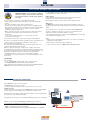
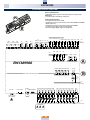
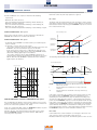
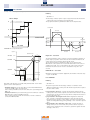
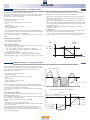
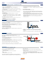
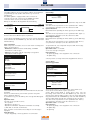
25
EWCM9900
FAN CONTROL
ENABLING
• Control is activated after a delay of 565 - odo
• Parameter 520-Fnty must be non-zero
• a temperature probe or pressure probe must be configured for discharge
control (control probe HP)
YOU can select digital output fan control by setting 520-Fnty = 2 (max. 8
fans).
If 520-Fnty = 1 the fan battery will be controlled by a single analogue
output (control by means of INVERTER).
Fan control is a function of the HP control probe.
Use parameter 548-UMFn to select both pressure control (bar/PSI) and
temperature control (°C/°F). Note that, if using temperature control and
the HP control probe is a pressure transducer, discharge control is a
function of the value converted into temperature of the selected gas, by
the HP control probe.
Behaviour is dual if the HP control probe is a temperature probe and the
control selected with 548-UMFn is pressure control.
Parameter 548-UMFn can be modified during normal operation.
The default discharge control is pressure (bar).
Note: The unit of measure shown on the display may differ from the
control unit.
Three controls can be selected with parameter 301 - FCFn:
0 = Proportional band control (BP)
1 = Dead band control (ZN)
2 = P.I.D. control (PID)
In case of proportional band control, parameter 551-Stty controls the
lateral and central setpoint relative to the control band.
Fans can be activated by reference to 302-FACt:
0 = independently of compressor status;
1 = if at least 1 compressor is on.
INVERTER FAN
To configure fan control by a single analogue output, set parameter 520Fnty = 1:
• Analogue output fan control
• Digital output to activate INVERTER (optional)
• Digital output for INVERTER error (optional)
• Error conditions are signalled by digital inputs (fan thermal switch with
continuous control).
Note: Parameter 521-nFn (number of fans) is not significant in this case
inasmuch as the INVERTER analogue output is used.
INVERTER fan - max. speed
If the discharge controller requires a power greater than 311-InSSP, the
INVERTER will nonetheless be controlled at 311-InSSP.
INVERTER fan - min. speed
• If 309-InLSP = 0 the INVERTER is controlled at the speed defined by the
discharge controller;
• If 309-InLSP is non-zero, there are two options:
- the discharge controller request is less than 309-InLSP but non-zero:
the INVERTER is forced to the default minimum speed set in 309-InLSP.
In this case if the control probe HP < 345-InLPt and delay 565-PAo
(alarm de-activation at switch on) has expired, the INVERTER switches
off and the enabling digital output is de-activated.
- the discharge controller request = 0 the behaviour of the INVERTER is
determined by 330 - InoS:
• If 330-InoS =0 the INVERTER continues to be controlled at the
minimum speed defined by 309-InLSP for the period 328-Inot after
which the INVERTER is switched off and the enabling digital output
is de-activated.
• If 330-InoS =1 the INVERTER contrinues to be controlled at the
minimum speed defined by 309-InLSP
Suction controller request
DIGITAL FANS
To control the fans by digital outputs, set parameter 520-Fnty =2:
309 - InLSP
Digital output fan control
Error conditions are signalled by digital inputs (digital fan thermal switch).
Suction controller actuation
Digital fans - timings
• Parameter 324-don defines the delay, in seconds, between the calls for
two different steps (activation of two different fans).
• Parameter 325-doF defines the delay, in seconds, between the release of
two different steps (de-activation of two different fans).
Time
309 - InLSP
Timer
Timer not expired
Timer expired
Time
328 - Inot
Digital fans - rotation
Parameter 322-rot defines the rotation of fans during calls and releases to
obtain the same number of hours of operation.
• 0 = fixed sequence: the activation sequence is fan 1, 2, 3... with deactivation in the inverse order.
• 1 = rotation: during activation, the fan with least hours of operation is
chosen; during de-activation, the fan with the most hours of
operation. The aim is balance out the hours of operation between all
fans.
Consent relay
Time
ON
OFF
Time
Speed flag forced to minimum
YES
NO
FAN PICKUP
Time
When first switched on, the fans are forced to maximum power for the
time defined by 323-Clt:
• Maximum power is 100% for digital fans
• Maximum power is determined by parameter 311 - InSSP for INVERTER
fans.
If 323 - Clt = 0 there is no pickup.
After pickup, the fans are run as required by the discharge controller.
In case of an alarm which locks out the fan battery, the fans are switched
off in any case.