1
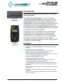
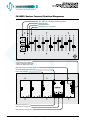
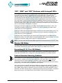
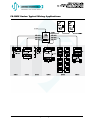
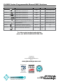
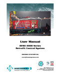
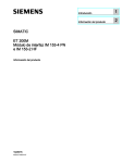
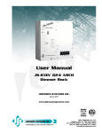
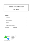
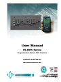
User Manual
CS-DMX Series
Programmable Manual DMX Stations
JOHNSON SYSTEMS INC.
www.johnsonsystems.com
Contents
Warranty...........................................................................................................2
User Manual Copies.........................................................................................2
Introduction.......................................................................................................3
Features...........................................................................................................3
CS-DMX Series Control Station Diagrams.......................................................4
“ON”, “DIM” and “OFF” Buttons with Integral LED’s.........................................5
Master (M) Slider..............................................................................................5
Secondary (3, 6, 9 or 12) Sliders......................................................................5
Control Station Security Feature......................................................................5
Power Supply Requirement..............................................................................6
Control Station Wiring......................................................................................6
DMX Input and Output Wiring..........................................................................6
Wiring an Independent Control Station............................................................7
Wiring a Single or Multiple Entrance Control Stations
to a Master Control Station...............................................................................7
Wiring Two or More Master Control Stations Together with “Take Control”......7
Wiring Two or More Control Stations Together with “Mimic”.............................8
Mounting the Control Station............................................................................8
Calibrate the DMX Output Range.....................................................................8
Configure the Control Station Using a CS-IPRO Wireless
Hand-Held Programmer...................................................................................8
Time Fade........................................................................................................9
Set the Adjustable Time Fade..........................................................................9
Set the Button LED Intensity............................................................................9
Local Lockout Mode Activation.......................................................................10
Remote Lockout Mode Activation...................................................................10
Short Circuit and Overload Protection............................................................10
CS-DMX Series Typical Wiring Applications...................................................11
Warranty
All CS-DMX Series control stations come with a standard one (1) year limited
warranty against defects in parts and workmanship.
User Manual Copies
Additional copies of the most recent version of this manual can be
downloaded at:
http://www.johnsonsystems.com/pdf_files/jsi_cs_dmx_manual_rev_1.pdf.
Note: Refer to the CS-IPRO user manual for detailed programming
information.
2
www.johnsonsystems.com
Introduction
Multi-Station, multi-room manual DMX controls for a full DMX
universe of control!
CS-DMX Series
Programmable Manual
DMX Station
Value, power and complete flexibility in a “green”, user friendly,
cost-effective package! The DMX Series of controls are the most
capable manual “stand-alone” DMX controls available. These field
programmable controls support 512 channels of DMX data with
digitally adjustable fade times. Multiple stations can be daisy-chained
together on the same control wire permitting multiple stations per
room. Each station can be individually programmed with our wireless
infrared hand-held programmer (Model Number: CS-IPRO) permitting
any slider/channel assignments imaginable.
Available from single to 12 channels with master, preset and take
control functions. Two and three button entrance station can be
remotely “locked out” for application where access needs to be
limited. This series of controls will operate on DC supply voltages
up to 18 volts. Adjustable time fade and LED intensity allow
customization for demanding applications. Durable powder-coat finish
is available in either black or white.
CS-IPRO
Wireless Hand-held
Programmer
Features
• Manual DMX at your fingertips.
• Six models/sizes available including two and three button entrance
stations.
• 512 DMX channels of control per station.
• Multiple stations can be daisy-chained on the same DMX line.
• Digitally adjustable fade-times and LED brightness.
• Station programming via low cost, wireless infrared hand-held remote.
• Local or remote/entrance station lockout options.
• Short-circuit and over-current protection.
• Ruggedly built for reliability and longevity.
• Tough, durable powder coat paint on 0.080” aluminum laser cut
faceplate for a scratch resistant non-glare finish.
• Color matched and sized for use with Johnson Systems AP Series
adapter plates where necessary to adapt to existing (larger) electrical
back boxes.
• Metal shaft sliders and machine screw mounting help prevent broken or
missing parts.
• Heavy-duty "high tactile" pushbutton switches are rated for 5 million
operations.
• Optional 6 Port Cascading Installation Merger permits low cost DMX
universe combining.
www.johnsonsystems.com
3
CS-DMX Series Control Station Diagrams
"ON", "DIM", and "OFF" Buttons With Integral LED's
Master (M) Slider
Infared LED Sensor
Secondary (3, 6, 9, or 12) Sliders
6-Position Connector (J1) For:
• Power Supply Input (COM, V+)
• Button Contacts (ON, DIM, RST)
• Master Pot (MP) Analog Output
DMX Output Range Calibration Jumper (JP1)
Security Enable/Disable Jumper (JP2)
Factory Only Jumper(s)
DMX Input Connector (J1)
DMX Output Connector (J2)
DMX Termination Jumper (JP1)
4
www.johnsonsystems.com
“ON”, “DIM” and “OFF” Buttons with Integral LED’s
All CS-DMX Series control stations contain 3 buttons with integral blue LED’s. When a button
is pressed, the control station is triggered into the corresponding state. The button LED’s
indicate the state of the control station. Under normal operation, when a button is pressed, the
corresponding LED will illuminate. If the control station is fading, the LED will flash once per
second until the fade is complete. Pressing a button or adjusting the master slider level while
the control station is fading, cancels the fade and immediately activates the button pressed. The
button LED’s also indicate when local or remote lockout is active, or if there is a short-circuit or
overload condition (refer to page 10 for details). The intensity of the button LED’s can be adjusted
(refer to “Set the Button LED Intensity” on page 9).
Pressing the “ON” button triggers all of the DMX channels patched to the sliders to full on. The
“ON” button corresponds with the “ON” connection on J1 and is optionally connected to other
control stations for various applications.
Pressing the “DIM” button activates DMX output control from the slider potentiometers (pots). The
“DIM” button corresponds with the “DIM” connection on J1 and is optionally connected to other
control stations for various applications.
Pressing the “OFF” button turns off (zero percent (00%) output level) all of the DMX channels
patched to the sliders. The “OFF” button corresponds with the “RST” (reset) connection on J1 and
is optionally connected to other control stations for various applications.
NOTE: The control station will still transmit DMX output levels at zero percent (00%) in the “OFF” state.
Master (M) Slider
The master slider controls the overall maximum DMX output level for the secondary sliders.
It has similar functionality to a grand master slider found on some DMX control consoles.
Secondary (3, 6, 9 or 12) Sliders
Each of the secondary sliders control the DMX output level for all the DMX channels patched
to the slider. Each slider can be configured to control any combination of 512 DMX channels.
Control Station Security Feature
All CS-DMX Series control stations have the capability to enable or disable the security feature.
Once security is enabled, the security key programmed in the control station must match the
security key in the CS-IPRO programmer, to be able to make programming changes to the
control station. The security feature eliminates the possibility for tampering with the control station
programming. The security feature is disabled by factory default.
If the security feature is required, it should be implemented at the time of installation. To enable
the security feature, set the SECURITY jumper (JP2) in the ENABLE position. Once installation of
the CS-DMX control station is completed, refer to the CS-IPRO user manual SECURITY menus
(EDIT KEY, SET KEY and GET KEY) for detailed programming and setup information. The default
8-digit security key for all CS-DMX Series control stations is set at all zeros (00000000).
www.johnsonsystems.com
5
Power Supply Requirement
The control station requires a regulated DC power supply from 10.6VDC to 18VDC. A 12VDC
power supply is recommended. The power supply common (V-) connects to the “COM”
connection on J1 and the power supply positive (V+) connects to the “V+” connection on J1.
Control Station Wiring
CS-DMX Series control stations can be wired for various applications. The control station wiring
can be configured for the functionality required.
A 6-position breakaway connector (J1) is used to connect the power supply (COM, V+), three
switches (ON, DIM, RST), as well as the master pot (MP) analog output (not used with CS-DMX
Series control stations).
The recommended wire for these connections is stranded, #18 AWG copper wire, however
smaller gauge wire may be suitable for some applications where distances are less than
150' (50m). The breakaway connector will accept wire sizes from #28 to #12 AWG.
Breakaway connectors are provided for all wiring terminations. For proper termination, the strip
length should be 0.28" (7mm). A 1/8" (3.2mm) flat head screwdriver should be used to tighten the
connections and torque to 3.5Lb-In (0.4Nm).
DMX Input and Output Wiring
All CS-DMX Series have a 3-position breakaway connector used to receive DMX in (DMX IN) and
a 3-position breakaway connector used to transmit DMX out (DMX OUT). The DMX received on
the DMX in (if applicable) connector is merged with the DMX generated by the control station and
retransmitted through the DMX out connector. Merged DMX data is highest takes precedence
(HTP) for equivalent DMX control channels. There is only a 1-packet (28msec) delay in the
retransmitted DMX from the original DMX received!
For proper termination, the strip length should be 0.28" (7mm). A 1/8" (3.2mm) flat head
screwdriver should be used to tighten the connections and torque to 3.5Lb-In (0.4Nm). Be sure to
isolate and protect all shield wires and comply with standard RS-485 termination practices.
• DMX IN (SHIELD/COMMON, DATA-, DATA+) is terminated on the J1 connector.
• DMX OUT (SHIELD/COMMON, DATA-, DATA+) is terminated on the J2 connector.
• Complies with USITT DMX512-A (ANSI E1.11 - 2008), standard protocol for digital data
control.
• Recommended cable is Beldon 9829, 9842, Cat 5 or equivalent (low-capacitance, twisted pair).
• Wiring must follow a daisy-chain topology.
• Maximum of 32 receiving devices on a single DMX line.
• Maximum cable length is 1,500 feet (455 meters).
• For more information, Google DMX, or visit: http://www.usitt.org/DMX512FAQ.aspx
NOTE: For long DMX lines exceeding 1,000 feet (305 meters) the “DMX TERM” jumper (JP1)
should be in the terminated (upper) position.
NOTE: Be sure the last DMX receiving device (end-of-line) is terminated with a 100Ω to 120Ω
resistor.
6
www.johnsonsystems.com
Wiring an Independent Control Station
An independent control station requires 2 conductors for V+ and common, and a single DMX
cable for the DMX out connection.
CS-DMX-12
COM
DC POWER SUPPLY COMMON (V-) INPUT
V+
DC POWER SUPPLY POSITIVE (V+) INPUT
DMX OUT
Wiring a Single or Multiple Entrance Control Stations
to a Master Control Station
An entrance control station (Part Numbers: CS-SA-ENT2B and CS-SA-ENT3B) is typically
installed at an entrance location and used to trigger a master control station into the “ON”, “DIM”
or “OFF” state. The entrance station(s) and master station mimic each other when a button
is pressed. Wiring between a single or multiple entrance stations and master station requires
2 conductors for V+ and common, and 3 conductors for the switches (ON, DIM and RST), 1
conductor for each switch function. A single DMX cable is required from the master control station
to the DMX receiving device.
CS-SA-ENT3B
CS-SA-ENT3B
COM
COM
COM
COM
ON
ON
ON
ON
V+
DIM
RST
V+
V+
DIM
DIM
RST
RST
CS-DMX-12
COM
V+
V+
DIM
DC POWER SUPPLY COMMON (V-) INPUT
DC POWER SUPPLY POSITIVE (V+) INPUT
RST
DMX OUT
CS-SA-ENT2B
CS-SA-ENT2B
CS-DMX-12
COM
COM
COM
COM
ON
ON
ON
ON
V+
RST
V+
V+
RST
RST
COM
V+
V+
RST
DC POWER SUPPLY COMMON (V-) INPUT
DC POWER SUPPLY POSITIVE (V+) INPUT
DMX OUT
Wiring Two or More Master Control Stations
Together with “Take Control”
When two or more master control stations are controlling the same device (DMX channels), “take
control” is typically required. When a button is pressed on one of the master control stations, it
will automatically “take control” from the other master control stations and put them in the “OFF”
state. Wiring between the master control stations requires 2 conductors for V+ and common, and
1 conductor for reset (RST) “take control”. A DMX cable between the control stations is required,
along with a DMX cable from one of the master control stations to the DMX receiving device.
CS-DMX-12
CS-DMX-12
COM
COM
RST
RST
V+
DMX OUT
V+
COM
V+
DMX IN
www.johnsonsystems.com
DC POWER SUPPLY COMMON (V-) INPUT
DC POWER SUPPLY POSITIVE (V+) INPUT
DMX OUT
7
Wiring Two or More Control Stations Together
with “Mimic”
“Mimic” refers to pressing a button (“ON”, “DIM” or “OFF”) on a control station, and the other
control station(s) are automatically triggered into the same “ON”, “DIM” or “OFF” state. The
analog output(s) could be controlling the same device or completely different device. Wiring
between the control stations requires 2 conductors for V+ and common, and 3 conductors
(2 conductors for Part Number: CS-SA-ENT2B) for the switches (ON, DIM and RST), 1 conductor
for each switch function. A DMX cable between the control stations is required, along with a DMX
cable from one of the master control stations to the DMX receiving device.
CS-DMX-12
COM
COM
ON
ON
V+
DIM
RST
DMX OUT
CS-DMX-12
V+
COM
V+
DIM
DC POWER SUPPLY COMMON (V-) INPUT
DC POWER SUPPLY POSITIVE (V+) INPUT
RST
DMX IN
DMX OUT
Mounting the Control Station
The control station can be mounted on/in a gangable (usually masonry) type of back box
with a minimum depth of 2" (50.8mm) and a preferred depth of 3.5" (88.9mm). A #2 Phillips
head screwdriver is required to secure the control station, using the provided black #6-32 x 1"
(25.4mm) mounting screws.
NOTE: Ensure the back box is earth grounded to protect the control station from electrostatic
discharge.
NOTE: Ensure the back box mounting-hole threads are not damaged. Damaged threads on the
back box can damage the threads on the mounting screws and cause stripping. The back
box threads can quickly be cleaned up by running a #6-32 tap through the mounting hole.
Be sure not to over-tighten the mounting screws or this could result in stripping the back
box mounting-hole threads.
Calibrate the DMX Output Range
All CS-DMX Series control stations are factory calibrated for 0-100% DMX control with a 10.6VDC
to 18VDC power supply. If the control station does not have a full range of DMX control, please
consult a factory representative.
Configure the Control Station Using a CS-IPRO
Wireless Hand-Held Programmer
To configure the control station, a Johnson Systems Inc. Model Number: CS-IPRO wireless handheld programmer is required. The CS-IPRO is required primarily to configure the DMX channel
patch for each of the sliders, however, it provides several other useful features.
Wireless communication between the CS-IPRO and CS-DMX Series control stations is via
bidirectional infrared LED’s. The control station infrared LED window is located between the
master (M) slider and slider 1. The maximum range for sending and receiving data between the
control station and CS-IPRO is 12" (30cm).
NOTE: Refer to the CS-IPRO user manual for detailed programming information.
8
www.johnsonsystems.com
Time Fade
The control station is capable of fading from:
“OFF”
“ON”
“ON”
“OFF”
“OFF”
“DIM”
“DIM”
“OFF”
The control station is capable of pseudo fading from:
“DIM”
“ON”
“ON”
“DIM”
The control station automatically begins fading when a button is pressed. The button LED flashes
on and off once per second to indicate fading.
NOTE: Pressing a button or adjusting the master slider level while the control station is fading,
cancels the fade and immediately activates the button pressed.
Set the Adjustable Time Fade
The time fade can be adjusted from 0 to 60 seconds. The factory default time fade is 5 seconds.
NOTE: Be sure the local and remote lockout modes are deactivated before adjusting the time fade.
Procedure:
• To set the adjustable time fade, press and hold the “ON” button for approximately 10
seconds, until the “ON” LED extinguishes.
• Release the “ON” button and count the number of times the “ON” LED flashes on.
Each time the “ON” LED flashes on, 1 second of time fade is represented.
• Once the required number of times the “ON” LED flashes on is counted, press the “ON”
button to save the time fade and exit.
• To set the time fade to zero (no fading), press and hold the “ON” button for approximately
10 seconds, until the “ON” LED extinguishes. Release the “ON” button and immediately
press the “ON” button again before the “ON” LED flashes on.
Set the Button LED Intensity
The button LED intensity can be adjusted to a preferred intensity level for various environments.
NOTE: Be sure the local and remote lockout modes are deactivated before adjusting the button
LED intensity.
Procedure:
• To enter the button LED intensity adjust mode, press and hold the “ON” and “OFF” buttons
at the same time for approximately 10 seconds, until all the button LED’s illuminate.
• Press the “ON” button to increase the button LED intensity. Press and hold the “ON” button
to accelerate the intensity adjustment.
• Press the “OFF” button to decrease the button LED intensity. Press and hold the “OFF”
button to accelerate the intensity adjustment.
• Once the preferred button LED intensity has been set, press the “ON” and “OFF” buttons at
the same time to exit the button LED intensity adjust mode and save the setting.
NOTE: There is a minimum button LED intensity so the control station will always indicate its
mode of operation/state.
www.johnsonsystems.com
9
Local Lockout Mode Activation
When the local lockout mode is activated, the control station is locked in the “OFF” state.
Any button press is ignored and the “OFF” LED flashes once to indicate local lockout mode is
activated.
Procedure:
• To activate the local lockout mode, press and hold the “OFF” button for approximately
10 seconds, until the “OFF” LED extinguishes.
• To deactivate the local lockout mode, press and hold the “OFF” button for approximately
10 seconds, until the “OFF” LED illuminates.
Remote Lockout Mode Activation
When the remote lockout mode is activated, the control station ignores all remote control station
key presses. The active LED flashes off for 0.1 seconds every 2 seconds to indicate remote
lockout mode is activated.
Procedure:
• To activate the remote lockout mode, press and hold the “DIM” button for approximately
10 seconds, until the “DIM” LED flashes off for 0.1 seconds.
• To deactivate the remote lockout mode, press and hold the “DIM” button for approximately
10 seconds, until the “DIM” LED flashes off for 0.1 seconds.
Short Circuit and Overload Protection
The control station is equipped with short circuit and overload protection. The short circuit limit is
set at 100mA with 0.6W of power dissipation. When a short circuit or overload is detected while in
the “ON” or “DIM” state, all of the button LED’s flash on and off to indicate there is a short circuit
or overload condition. The control station automatically recovers to normal operational state once
the short circuit or overload is removed.
10
www.johnsonsystems.com
CS-DMX Series Typical Wiring Applications
www.johnsonsystems.com
11
CS-DMX Series Programmable Manual DMX Stations
Model
Description
# Wires
Back Box
Minimum PCB Clearance
1 gang, 3 channel manual control
w/master slider, on, preset, and off
2 x #18 AWG
+DMX
CS-DMX-3-?
2 gang
3.60"W x 2.75"H x 2.00"D
9.1cm x 7.0cm x 5.1cm
CS-DMX-6-?
2 gang, 6 channel manual control
w/master slider, on, preset, and off
2 x #18 AWG
+DMX
3 gang
5.50"W x 2.75"H x 2.00"D
14.0cm x 7.0cm x 5.1cm
CS-DMX-9-?
3 gang, 9 channel manual control
w/master slider, on, preset, and off
2 x #18 AWG
+DMX
4 gang
7.30"W x 2.75"H x 2.00"D
18.5cm x 7.0cm x 5.1cm
CS-DMX-12-?
4 gang, 12 channel manual control
w/master slider, on, preset, and off
2 x #18 AWG
+DMX
5 gang
9.10"W x 2.75"H x 2.00"D
23.1cm x 7.0cm x 5.1cm
CS-SA-ENT2B-?
1 gang, 2 button (on/off) entrance station with
adjustable “on” voltage for stand-alone applications
5 x #18 AWG
1 gang
1.80"W x 2.75"H x 2.00"D
4.6cm x 7.0cm x 5.1cm
CS-SA-ENT3B-?
1 gang, 3 button entrance station
w/on, preset, and off
6 x #18 AWG
1 gang
1.80"W x 2.75"H x 2.00"D
4.6cm x 7.0cm x 5.1cm
CS-IPRO
Hand-held Infrared Station Programmer
Wireless
N/A
N/A
DMX-6PIM
DMX 6 Port (6IN/1OUT) Cascading Merger
120VAC
+ 7 DMX or CAT5E
Wall Mount
or Flush
Mount
N/A
2.75"W x 4.95"H x 1.00"D (70cm x 125cm x 25cm)
9.5"W x 12"H x 3.5"D (24cm x 30cm x 9cm)
For other control products and solutions
please visit WWW.JOHNSONSYSTEMS.COM
User Manual
CS-DMX Series
Programmable Manual DMX Stations
Rev. 1
www.johnsonsystems.com