1
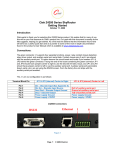
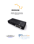
D2000
User Guide
Unit 11 – 33 Riley Road – Woodmead
+ 27 11 612 3660
[email protected]
www.gc-sat.com
Document Part# 100342
Revision: A
May, 2009
Contents
System Overview.............................................................................................................4
Physical Attributes ...........................................................................................................6
Front Panel – D2000 ....................................................................................................6
Back Panel ...................................................................................................................7
Embedded Software ........................................................................................................9
Accessing web pages...................................................................................................9
Web Pages.................................................................................................................10
D2000 Display Features ................................................................................................18
Signal Strength Indicators ..........................................................................................18
Short Code Messages................................................................................................18
Using Trip Plan Features............................................................................................20
Viewing Status Information.........................................................................................22
Quick Position/Mayday Button ...................................................................................23
Adjusting Settings.......................................................................................................24
Creating D2000 profile from SkyRouter .........................................................................25
Customizing Section 1: “D2000 Profile Settings”........................................................25
Customizing Section 2: “Short Code” .........................................................................26
Customizing Section 3: “Trip Plan”.............................................................................26
Assigning & Sending A Profile To A D2000 ...................................................................27
Locating The Assets Management Window ...............................................................27
Adding A Profile To A D2000 .....................................................................................27
Updating Your D2000 With A D2000 Profile...............................................................27
How Do I Know That the Updating Process Was Successful?...................................27
SkyRouter API ...............................................................................................................29
Page 2
Proprietary Notice
Information contained in this document is proprietary and remains the exclusive
property of Blue Sky Network and Gilcom Technologies, Inc.
Warning
Blue Sky Network reserves the right to update this documentation at any time. Users
are directed to our web-site (www.blueskynetwork.com) for the most current version of
this document.
Page 3
System Overview
The Blue Sky Network D2000 terminals and the SkyRouter portal provide global
position reporting, trip planning, two-way messaging, and telemetry reporting.
The SkyRouter Network
The SkyRouter network allows users to communicate with and operate D2000 terminals
all over the globe. The network provides account management features, D2000 unit
configurations as well as an e-mail message interface and web-based tracking.
The SkyRouter network also provides a Web Service interface for data extraction to 3rd
party software. Please contact Blue Sky Network for more information or visit
www.skyrouter.com/DataExchange.
Blue Sky Network D2000 SATCOM Terminals
D2000 terminals can be operated after the terminal has been connected with power and
an antenna. Please refer to the Installation manual, to ready your D2000 for operation.
Web pages (hosted on the D2000 unit) can be accessed using any device with a
standard Ethernet connector and a standard Internet browser (such as Internet Explorer
or Mozilla Firefox).
This user guide
This User Guide describes the D2000 terminal’s physical attributes, its features and
use. A separate User Guide covers the SkyRouter network.
For installation related topics, please consult the D2000
(http://www.blueskynetwork.com/Support/InstallationGuides.php).
Installation Guide
System requirements
The only requirements for accessing the functions of the web pages hosted on the
D2000 is a PC, laptop, or PDA (such as an HP iPaq) with an Ethernet interface and a
standard Internet browser, such as Internet Explorer or Mozilla Firefox. Accessing these
web pages is not required for normal tracking operation, but allows for full two-way
messaging, sending trip plans and more (see page 11 for more information).
Page 4
For illustration only. The SkyRouter network works equally well with any type of mobile asset.
Page 5
Physical Attributes
The Blue Sky Network D2000 is available in 3 versions; Land, Marine and Aviation. The
D2000 includes a two-line, 16-channel LCD interface (to system features and system
information). It also hosts web pages accessed through a built-in Ethernet port on the
back panel. Any standard device such as a laptop or a PDA with an Ethernet connection
and a standard Internet browser can be used.
Front Panel – D2000
B
A
C
D
E
F
A
A. Quick POS Button
D. OK/Accept Button
B. LCD Display
E. Clear Button
C. Menu Navigation Button
F. Numerical Keypad
Page 6
Back Panel
A & B) Antenna Connectors
•
The “Iridium Antenna” TNC connector connects to the Iridium connector on the
antenna. FAA aviation-approved antennas have a TNC connector for Iridium,
while the land and marine antennas have an SMA connector. The corresponding
cables/connectors are provided in the D2000 Kit.
•
The “GPS Antenna” SMA connector connects to the GPS connector on the
antenna.
C) Power Port
•
The D2000 power connector is an EN3 Switchcraft (circular 8-pin) connector that
operates at 10-30VDC. Please see power wiring diagram for supplying power to
the unit.
•
Please note: If power is supplied via the optional cigarette lighter adapter, we
strongly recommend that your vehicle’s cigarette lighter provides a Switched (and
not Constant) power source. This will prevent the D2000 from draining the main
battery while the vehicle is turned off.
D) On/Off Switch
Page 7
E) Serial Port
•
This port is for connecting a “message indicator” can be connected to this port. It
could be an LED light or a small speaker. For more information, please see the
D2000 Installation Guide.
Please note: The DB9F port has limited capability. 3rd party devices such as
sensors need additional software to function. BSN is not responsible for
developing software for such devices.
F) Maintenance Port
•
This port is used for firmware upgrades. This port should be accessed by trained
personnel only.
G) Ethernet Port
•
Software on the D2000 unit is accessed through the Ethernet port on the back
panel. A standard Ethernet cable is required.
•
If proper activity has been established, a green LED will flash on the Ethernet
port.
Page 8
Embedded Software
The D2000 system is capable of GPS position reporting, sending and receiving text
messages and transmission of telemetry data.
The user can access HTML Web Pages that enable:
•
Access to the Trip Plan
•
Access to 2-way e-mail messaging functionality
•
Checking the status of the unit.
•
Changing unit parameters (password protected).This can also be achieved
remotely from the SkyRouter network.
Accessing web pages
Upon attaching the external device to the D2000, access the web pages on the D2000
can be made. One of three approaches can be made to access the pages:
1. After attaching the Ethernet cable, open the web browser and wait for it to
resolve its home page to the default page of the D2000, the Trip Plan web page.
If this does not work try step two.
2. After opening a web browser that didn’t resolve to the default page, try entering
“D2000” in the address bar. If this does not work go to step three.
3. Enter the IP-address of the web server residing on the D2000 in the web
browser’s address bar. The IP-address is: http://192.168.1.120 .
If the web browser still doesn’t resolve to the Trip Center web page, it may be required
to renew the IP configuration of the access device.
Renew IP-configuration
To renew the IP-configuration of an access device running a Windows operating system
open a command line window by selecting: “Start”, “Run” and enter “command” (or
“cmd” for Windows NT, 2000 and XP).
Windows 95, 98, ME:
Windows NT, 2000, XP:
Type the following two commands:
C:> ipconfig /release_all
C:> ipconfig /renew_all
C:> ipconfig /release
C:> ipconfig /renew
For PDA’s please attempt a soft reset to renew the IP configuration of the device.
For other operating systems please consult the specific system documentation.
Page 9
Web Pages
Trip Plan
Special GPS reports: The Trip Plan allows you to send five different special types of
GPS reports: Start, Stop, Available, Picking up, and Dropping off.
Start GPS Message: Click the start message to indicate that a new trip is
starting. The D2000 will immediately attempt to send the report. If the message is
successfully sent over the Iridium network, you will be returned to the Trip Plan
page. If the attempt is unsuccessful you will get an error message. This is true for
all five special GPS message types.
• Stop GPS message: Click the Stop button to send a special GPS report
indicating a trip in progress has stopped.
• Available GPS message: Click the Available button to send a special GPS report
indicating that the asset is available for another trip.
• Picking up GPS Message: Click the Picking Up button to indicate that the asset is
picking up its payload.
• Dropping off GPS Message: Click the Dropping off button to indicate that the
asset is dropping off its payload.
Trip Plan: The Trip Plan section features a complete Trip plan. The Trip plan can be
filled out and sent to SkyRouter for viewing by dispatchers.
•
All time fields should be filled out in the following format (HH:MM) with a leading
0 (zero) for hours 0 through 9.This form will be saved into memory after sending
the Trip Plan, and will be available for viewing until the unit is turned off. After
sending this information by clicking the “Send Trip Plan” button it will appear on
the SkyRouter Trips page.
Note: There is very limited input validation for these fields.
Page 10
Inbox
The Inbox page displays a summary of the text messages currently stored in the D2000.
Information displayed includes: Subject, Sender, and Date/Time.
•
Only a limited subset of headers is displayed in the Inbox. Included in the page
are hypertext links to “next”, “first” and “last” to display other subsets of the inbox
messages.
•
For each text message line there are links to the “Your Message” page displaying
the selected message. Links to the message exist for Subject, Sender, and Date
fields.
•
The D2000 terminals support up to 20 messages in the Inbox.
•
We do not recommend sending a large amount of messages to any unit during a
short time interval (minutes). It may cause the unit to become unstable and reset
with loss of messages as a result.
NOTE: Powering off clears the inbox.
Page 11
Your Message
The complete message content is displayed on the “Your Message” page. This includes
From, Subject, Date/Time and the body of the message.
•
A “Delete” button is included in the “Your Message” page to delete the message.
•
A “Reply” button is included in the “Your Message” page to easily reply to the
message.
•
Upon reading any text message, including previously read messages, the
optional after-market MSG LED (attached via the serial port) is turned off.
Page 12
Compose
The “Compose” page allows the creation of text messages. There are four input fields
To, Address, Subject, and message body.
•
To send a message to a user on the Blue Sky Network website type “user
ID”@skyrouter.com in the “TO:” field. Example: [email protected].
•
To send a message to any other e-mail address, just enter the e-mail address in
the “To:” field.
•
To save an e-mail address in the internal address book check the “Save”
check-box before you send the e-mail. You can save up to 10 e-mail addresses.
The addresses will remain stored in the unit even after you turn the unit OFF.
•
Enter the subject of your message in the subject field and the remainder of the
text in the body. When you are done, click send. The maximum length of the
e-mail is 250 characters.
Page 13
Status
The status page contains information on the current state of the unit.
•
•
•
•
•
•
•
•
•
•
•
•
•
•
•
•
•
Version: This will display the current firmware version that is installed.
Iridium
Signal:
This
will
display
the
Iridium
signal
strength:
0(no signal) - 5(excellent).
Iridium Net Reg: This will display the current Iridium registration status.
IMEI Number: This will display the IMEI (International Mobile Equipment Identity)
Number. This is the number used to identify this specific tracking unit.
GPS Channels: This will display the current number of GPS satellites that you
are connected to at the present time.
Ethernet State: This will display the current state of the Ethernet Interface.
GPS Reports: This will display the current number of GPS Reports that have
been transmitted to SkyRouter since power up.
Text MSGS Received: This will display the current number of text messages
which includes e-mails that have been received.
Text MSGS Sent: This will display the current number of text messages and
e-mails that have been sent.
Sensor Reports: This will display the current number of reports that were sent
through the serial port.
Parameter Updates Received: This will display the current number of updates
that have been received that contain information about the settings.
Parameter Requests Replied: This will display the current number of replies to
settings requests from SkyRouter.
Data Messages Received: This will display the current number of data
messages that have been received.
Data Message Sent: This will display the current number of data messages that
have been sent.
Total Messages: This is a count of the current messages that are being stored in
the inbox.
Free Kbytes: This is a count of the size of available memory in Kilobytes.
Last GPS (Entire Section): This section will contain all information that is
currently being read from the onboard GPS module.
Page 14
Page 15
Settings
The settings page displays various D2000 parameters. A user may change these
parameters, then by entering the correct password and choosing the save option apply
these settings to the D2000 unit.
Explanation of parameters:
GPS Position Report
Turn GPS position reporting ON/OFF
Interval
Set regular GPS reporting interval
Message Polling
This feature is only important if GPS reporting is turned OFF. In that case
message polling will ensure that that other messages get to the unit.
Interval (sec)
Interval for text message checking.
Quick Position
Quick Position is always ON.
Interval (sec)
Reporting interval when Quick Position is activated.
Count
Number of Quick Position messages to be sent.
Speeding
Turn Altitude based reporting ON/OFF
Maximum Speed
Determine the speed at which a “Speeding” event will be transmitted
Perimeter Range
Turn Perimeter Range GPS reporting ON/OFF
Range (ft)
Determine the range within which the unit will start reporting at the perimeter
range interval. The unit will check every “regular GPS reporting interval” to
determine whether the unit has moved more than the Perimeter Range distance
from the previous measurement. If it has not, the perimeter range interval will be
in effect.
Interval (sec)
Perimeter range interval.
Serial Ports 1/2
Turn serial ports ON/OFF
Data Bits
Set data bits
Parity
Set parity
Baud
Set baud rate
Interval
Set transmission interval
Command
Set command to be sent through the serial port to alert the attached equipment
that the unit is ready to receive.
If command “RCVR” is specified, the unit will just read form the serial port buffer
at the set interval and transmit the contents of the buffer.
Page 16
Password
•
The Settings Password is required to change the parameters on the unit. It is not
advised to change the default password, but the option is available if needed.
•
To change the Settings Password, fill out the required fields on the bottom of the
settings page.
NOTE: There is NO WAY to reset the password if it is forgotten. PLEASE BE SURE
TO SAVE THE PASSWORD FOR THE UNIT(S).
Save Settings (Flash/non-Flash)
After changing settings on the unit enter the settings password.
The default password is: 1111
“Save Temporary” will save the settings until the next power cycle.
“Save Permanent” will save the settings to Flash memory and hence keep the settings
after a power cycle.
Restore Defaults
This button resets the setting to the factory defaults.
Reset
Resets all input fields.
NOTE: All setting can also be changed from the SkyRouter portal.
Page 17
D2000 Display Features
Signal Strength Indicators
Iridium Signal Strength
Iridium signal strength is indicated in the top right-hand corner of the display. The
current signal strength is indicated on a scale from 0-5. 0-1 is considered poor. 2-3 is
considered deficient. 4-5 is considered ideal.
GPS Signal Strength
GPS signal strength is indicated on a 0-5 scale much like the Iridium signal strength.
The scale is as follows:
GPS Signal
Receiver status
Dilution of Precision
0
No signal
-
1
2D
HDOP > 3
2
2D
HDOP ≤ 3
3
3D
PDOP > 10
4
3D
10 > PDOP > 5
5
3D
PDOP ≤ 5
Iridium transmission indicator
While the unit is attempting to send or receive messages over the Iridium network, the
keypad will be locked. A blinking cursor in the top left-hand corner of the display will
indicate that a transmission is taking place.
Short Code Messages
The D2000 allows the user to send up to 10 pre-programmed Short Code messages to
dispatch/operators/others via the SkyRouter asset management portal. There are two
methods to send Short Code messages. Users will be able to use the numerical keypad
as a quick reference to a Short Code or they can navigate to a submenu to view and
utilize a complete list of Short Codes. Both methods will be explained in this section.
Quick Keys for sending a Short Code Message
When “Messages” is selected (“>”) from the main menu numbers on the keypad
correspond to your predefined short codes. Pressing a number button on the keypad
will result in a short code being sent, after an acknowledgement.
Example: While the “Message” option is highlighted in the main
menu the user could press the ‘1’ button on the Numerical Keypad
Page 18
followed by pressing the “OK” button, these actions would result in
sending “Short Code 1” to the SkyRouter Web Portal.
Menu Navigation for Short Codes
Navigation through any menu on the D2000 is done by using the Menu Navigation
Button. A complete list of Short Codes available can be found under the “Messages”
menu by selecting “Short Codes”.
Example: If you set Short Code 1 to send a “Start” message, you
would be able to send the message by first highlighting the
“Messages” option by using the Up or Down Menu Navigation
Button. Then, pressing the Right Menu Navigation Button three
times. This would result in that message being sent.
New Message Notification
You will see a message indicator box begin to blink over the “:” in the Iridium signal
indicator (“I:5” blinking to “I█5”) when there is an unread message waiting.
This indicator will stop blinking as soon as any message in the Inbox is read.
NOTE: While there are unread messages in the Inbox, the normal transmission
indicator (blinking cursor in the top left-hand corner of the screen) will not be blinking.
Receiving & Reading Messages
You may read messages received to your inbox on the D2000. Your messages are
stored under the Messages/Read Messages menu.
”INBOX” is displayed on line 1. On line 2 it will display “Message [Current Message
Number] / [Total Messages]”. Then pressing the “OK” button will result in your message
being displayed. Use the Up or Down Menu Navigation button to view the entire
message. To read different messages select a different message number and press
OK.
Page 19
Acknowledge and/or Delete Messages
To acknowledge a message just press the “OK” button while reading the message. You
will be presented with options to acknowledge and/or delete the current message. An
acknowledged message is sent with an empty body and the word “ACKN:” added to the
beginning of the subject of the original message.
Using Trip Plan Features
A simple Trip Plan can be sent to SkyRouter from the D2000. You can send information
such as Origin, Destination, Departure Time, Estimated Time En-route, Distance, Fuel,
& People on board. The information will be displayed in the SkyRouter asset
management portal.
Sending a Trip Plan
To begin the process of sending a Trip Plan enter the Trip Plan submenu. The
information you will be prompted for is dynamic and may be adjusted at anytime by a
SkyRouter corporate account user. Information entered into the Trip Plan will contain
only numerical values. You may edit sections already completed by using the menu
navigation button. After you have completely filled out your Trip Plan, the screen will
display ”OK?”. Once you press the “OK” button your Trip Plan will be sent to the
SkyRouter Web Portal.
Origin
Name tags for numerical values can be assigned on SkyRouter. Talk to your SkyRouter
Administrator for more details.
Destination
Name tags for numerical values can be assigned on SkyRouter. Talk to your SkyRouter
Administrator for more details.
Page 20
Departure Time
This field will accept data in the format of a 24 hour clock. This information will be used
to calculate the ETA displayed on SkyRouter.
Ex. 13:30 (departure set for 13:30 or 1:30PM)
ETE
Estimated time En-route, this field will accept data in the format of hours and minutes.
This information will be used to calculate the ETA displayed on SkyRouter.
Ex: 02:35 (2 hours and 35 minutes)
Distance
This field requires a 1-5 digit number, and is represented in feet.
Ex. 6500 (Distance will be 6500 feet)
FUEL
This field will accept the hours of fuel remaining on the aircraft in hours and minutes
format.
Ex: 2:15 (2 hours and 15 minutes of fuel remaining)
POB
People on board, this field requires a number between 1 and 999.
Ex: 12 (12 people on board)
Page 21
Viewing Status Information
The status submenu will provide you with information about your current position. A list
of available information is shown below. The status menu is the third option down in the
main menu. Scroll down below “Trip Plan”.
Description of Information
Latitude: Latitude is given as an angular measurement in degrees ranging from 0° at
the Equator to ±90° at the poles,+90° for the North Pole or -90° for the South Pole.
Longitude: Longitude is given as an angular measurement ranging from 0° at the Prime
Meridian to +180° eastward and −180° westward.
Altitude: Altitude is given as the elevation above mean sea level and is represented in
feet.
Speed: Speed is given in terms of knots, 1 knot = 1 nautical mile/hour = 1.852 km/h
exactly.
Heading: Heading is represented by the number of degrees where as 0° would be
directly north, 90° is directly east, 180° is directly south, and 270° is directly west.
DOP (Dilution of Precision): When visible satellites are close together in the sky, the
geometry is said to be weak and the DOP value is high; when far apart, the geometry is
strong and the DOP value is low.
Interval (sec): This interval represents the number of seconds between position report
transmissions to SkyRouter.
Reports Sent: This is a count of the reports that have been sent since the D2000 was
supplied power.
IMEI: This is the Iridium modem identification number
Page 22
Quick Position/Mayday Button
Pressing
will activate or deactivate the quick reporting mode.
*Note- The quick position button will flash when it is active.
When the user activates the “Quick Position” button, all other actions will be
discontinued and the system will start sending a special alert. Ground personnel can be
notified via e-mail SMS, pager, or via the SkyRouter asset management portal. Since
the “Quick Position” button will override all other functions, you can press the “Quick
POS” button to begin sending Quick Position Reports immediately. When the “Quick
Position” button is activated the LCD Screen will display “Quick Pos Mode Active”, and
the “Quick Pos” button will flash. To deactivate the “Quick Position” function, press the
“Quick Pos” button again.
Page 23
Adjusting Settings
Display settings can be adjusted in the Setup submenu. A list of options is provided
below.
Brightness Options
Brightness can be set in the range of 1-10, 10 being the brightest. Remember to press
the OK button to save your settings.
Contrast Options
Contrast can be set in the range of 1-10. Remember to press the OK button to save
your settings.
Version Display
The current firmware installed on your D2000 can be displayed by entering the version
submenu.
Page 24
Creating a D2000 profile from SkyRouter
This section will cover how to customize a D2000 profile using the SkyRouter asset
management portal. The D2000 profile allows for customized personal Short Code
options, and Trip Plan options. After logging into your SkyRouter account at a Corporate
Account level you can locate the D2000 profile settings page by clicking the “D2000
Profile” link under the main “Pref” tab, shown below.
Customizing Section 1: “D2000 Profile Settings”
In the “D2000 Profile Settings” section you will find two fields; “Set Selection” & “Set
Name”, see below.
Set Selection: This field is an identifier to which profile you are currently viewing &
editing. You can customize up to five D2000 profiles. Clicking one of the numbered
bullets will refresh your page to display the current saved settings for that profile
selection.
Set Name: For each selection a name must be assigned. Profiles will be assigned by
name to each individual asset.
Page 25
Customizing Section 2: “Short Code”
In the “Short Code” section you will find two main parts; Short Code option activation
and deactivation and your customizable list of Short Codes, see below.
Short Code: This check box activates and
deactivates short codes.
Short Code Settings: There are 10
customizable short codes per profile. There
are predefined short codes available. The
predefined short codes are:
•
Start
•
Stop
•
Available
•
Dropping off
•
Picking up
The predefined short codes can’t be edited.
To customize a new short code select text
and enter the text to be displayed in it’s
corresponding display field.
Customizing Section 3: “Trip Plan”
In the “Trip Plan” section you will find two main parts; Trip Plan option activation and
deactivation and your customizable list of Trip Plan Fields, see below.
Trip Plan: This box will activate or deactivate the trip plan feature.
Trip Plan Field: Checking or un-checking any of these boxes will
enable or disable the user from entering the information into the
D2000.
Saving Your Profile
After you have completed filling out the information that is contained
in your D2000 profile you need to click the save button at the bottom
of the page.
Page 26
Assigning & Sending A Profile To A D2000
Locating The Assets Management Window
After logging into SkyRouter click the main “Asset” tab, see below.
Adding A Profile To A D2000
With the main “Assets” page loaded, click the “edit” link to the left of the Asset, see
below.
After clicking the “edit” link, a gray box will appear with the customizable information
pertaining to your asset. Select one of your profiles from the “D2000 Profile” menu.
Then, click the save button (see below).
If you have successfully added a profile to your asset you will be able to update your
D2000 with that profile.
Updating Your D2000 With A D2000 Profile
After assigning a profile to your asset you can click the “send” link to the far right and
your new profile will be sent to the D2000, see below.
How Do I Know That the Updating Process Was Successful?
First, click the history link to the far right of your asset.
Page 27
Now that you have clicked the “history” link a new page will appear, see below. The
information that appears will tell you the date & time your message was sent. If your
profile was successfully loaded it will be acknowledged with a corresponding date &
time.
Page 28
SkyRouter API
Blue Sky Network has developed a packet data API for 3rd party developers.
Developers can now, with extraordinary ease, develop messaging applications
on top of the SkyRouter platform. Applications can be developed for sending and
receiving messages through the D2000 Ethernet interface and on the ground
SkyRouter provides an interface for sending and retrieving messages.
Please contact Blue Sky Network
www.skyrouter.com/DataExchange.
for
more
information
or
visit
Page 29
More help needed?
Please do not hesitate to contact us either via e-mail or on the phone number listed
below. Thank you for using the SkyRouter network for your Asset communications
needs.
Blue Sky Network, 1298 Prospect Street, Suite 1D, La Jolla, CA 92037
Phone: +1 858 551 3894 | Fax: +1 858 551 3891
E-mail: [email protected] | Web: www.blueskynetwork.com
Page 30