1
The two signal lines (on the twisted pair) are receive/transmit plus (RT+) and
receive/transmit minus (RT-). The shield is connected to signal ground. It is
not directly connected to physical earth.
The cable should be one single run with no T-connections (stubs). Each end of
the cable must be terminated with an 120ohm resistor across the signal lines.
4.4.1 Providing Terminating Resistors
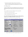
The CA100 is provided a 120ohm resistor for terminating the RS-485 line. The
resistor can be enabled (connected across the RS-485 line) by linking jumper
J12.
There is provision for a terminating resistor on the PC RS485 card. This is not
normally inserted. If the PC is the last device on the RS485 line then insert the
DB9 120ohm terminating connector provided on one of DB9 connectors.
NOTE: There must be exactly one 120ohm terminating resistor at each end of
the RS-485 line.
4.4.2 Bias Resistors
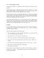
In environments with large amounts of electrical noise, it is necessary that one
pair of bias resistors be connected to the RS-485 cable. One 1.5K resistor is
connected between the RT+ line and +5V, and another between RT- and signal
ground.
Each CA100 is provided with a pair of bias resistors, however it is
recommended that these resistors be disabled, as the PC interface board has its
bias resistors permanently installed.
It is recommended that the bias resistors be enabled on the PC interface board
and disabled on all other devices on the RS-485 line.
NOTE: There must only be one set of bias resistors on the RS-485 line.
4.4.3 The RS485 Ground Fault Fuse
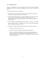
Fuse F1 on the CA100 is a “Ground Fault Fuse” for the RS-485 interface. Its
purpose is to protect the RS-485 electronics from large differences in ground
potential from one CA100 or PC to another. Such differences will normally
only be caused by faults.
If it is necessary to replace the fuse, use a type M205 with a 1A rating.
8