1
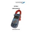
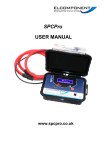
SPCMini USER MANUAL www.spcmini.com SPCMini User's Guide Copyright © 2010 Elcomponent Ltd All Rights Reserved. The information in this document is subject to change without notice. Elcomponent Ltd has made every effort to ensure the accuracy of this manual. However, Elcomponent Ltd makes no warranties with respect to this documentation and disclaims any implied warranties of merchantability and fitness for a particular purpose. Elcomponent Ltd assumes no responsibility for any errors that may appear in this document. Trademarks IBM is a registered trademark of International Business Machines Corporation. Windows is a trademark of Microsoft Corporation. All other product names are copyright and may be trademarks and/or registered trademarks of their respective companies. Symbols: The following symbols may be used in this manual WARNING: Failure to follow the instructions may result in personal injury or damage to the instrument. PC Specification: The SPCMini has a large memory capacity and utilises USB as its communication and data transfer protocol. This requires a PC of the following minimum specification to make best use of the product’s capabilities. Windows: Processor: RAM: Display: Windows XP/ Vista/W7 Pentium 4 or Centrino mobile 2.0 GHz+ 512MB+ 32 bit colour 1024 x 768 minimum 01.08.2012 ii CONTENTS SPCMini “At A Glance” … … INTRODUCTION … … … Description … … … SETTINGS & USE … … … Changing the Battery … … The Clip-On Ammeter … … Making Single Phase Measurements Making 3 Phase Measurements The DataLogger … … Switching the Unit Off … … POWERPACK SOFTWARE … … Loading the Software … … PowerPack Pro “At A Glance” … Communicating with the SPCMini Status … … Set-Up … … … Download … … USING THE GRAPHING PACKAGE … Selecting the Measurement Unit Using the Graph Tools … … Chart Tab … … Zoom … Show Data Values Show Alarm Values Show Gridlines Additional Graph Functions … Export to Microsoft Office Set Graph Options … Summary Tab … … … iii … … … … … … … … … … … … … … … … … … … … … … … … … … … … … … … … … … … … … … … … … … … … … … … … … … … … … … … … … … 01 02 03 04 04 05 05 07 08 11 13 13 14 15 16 17 17 20 21 21 21 21 23 23 24 24 24 24 25 Data Tab … … Selecting Data … Exporting Data Statistics Tab … … Costs Tab … … Adding & Amending Tariffs Alarms Tab … … File Structure … … Report Facility … … … … … … … … … … … … … … … … … … … … … … 26 26 27 27 28 28 29 30 31 APPENDICES Appendix 1 SPC Drivers … Appendix 2 European Settings … … … … 32 37 iv … … … … … SPCMini - ‘At A Glance’ Large jaw provides access for cables up to 40mm diameter Large 3 ½ digit display shows load in amps Selector switch for display current range On/Off / Digital Display Switch ‘Survey Running’ indicator and data overwrite warning indicator USB Socket 1 INTRODUCTION The SPCMini and its dedicated PC software package ‘PowerPackPro’ combine new technology and years of experience into an unbeatable lowcost package. It has a large clear display, a massive ‘Flash’ memory, and set-up and data download is via USB, compatible with virtually any PC running Windows XP or later. The SPCMini is also extremely versatile and will provide accurate results on loads as small as 2 amps, right up to a maximum of 500 amps. The logging interval is fully adjustable. The SPCMini is easy to use – clip it on, check the load with the on-board display, set it to log, press the start button and you’re done! It’s also clever – it won’t overwrite any previous surveys without warning you, and the logger electronics auto-ranges to ensure the highest levels of measurement accuracy at all times. The ‘PowerPackPro’ PC software package has been developed specifically for the SPCMini and is streets ahead of the competition. Designed by Mike Matthews, the architect of our acclaimed MeterRing MM aM&T package it combines outstanding ease-of-use with many powerful features for effective energy management. 2 DESCRIPTION The SPCMini combines the functions of a clip-on ammeter for measuring AC current, with a sophisticated data logger to record the measured current at the desired storage interval. The unit’s communications are via USB which provides connection to the PC, allowing the user to set up and download the logger via the PowerPackPro utility software supplied with the SPCMini. The SPCMini features simple controls (see ‘At A Glance ‘ on page 1) and may be used either as a simple clip-on ammeter or as a datalogger, as detailed below. 3 SETTINGS & USE CHANGING THE BATTERY The SPCMini is powered by a PP3 type 9VDC alkaline battery (Duracell MN1604 or equivalent). The battery powers both the clip-on ammeter display and the datalogger. A fully charged battery will give many hours of display time when the SPCMini is being used as a clip-on ammeter. A low battery condition is indicated by the ‘LOBAT’ warning appearing in the bottom left of the ammeter display. 0.00 LOBAT The battery voltage is also monitored by the PowerPackPro utility software (see page 16) allowing the user to assess the battery condition prior to initiating a survey. The datalogger features extremely efficient low power circuitry as well as a totally secure memory (recorded data are not dependent on the battery condition or presence) and a fully charged battery should provide sufficient energy for a survey lasing 4 weeks or more. However, it is recommended that a new battery be installed before starting a survey. To change the battery, the cover on the back of the unit is removed using a Phillips type screwdriver. The battery is then clipped onto the terminal block, ensuring that the correct polarity is respected. Replace the cover, ensuring that no cables are trapped or misplaced. 4 THE CLIP-ON AMMETER To use the SPCMini in ammeter mode, the selector switch should be set to ‘display’ (down) and the current selector switch set for the desired range. NOTE: If the load to be measured is not known, set the unit to the 500A range and reset it as necessary WARNING: Do not alter the range setting whilst a load is being measured as this could damage the unit. Always remove the SPCMini from the cable before resetting the range switch. Clip the unit around the conductor to be measured and read the current in amps on the LCD display. WARNING: Take care when working near live parts. Ensure that the power is turned off before exposing live parts. The SPCMini should be used on insulated conductors only. MAKING SINGLE PHASE MEASUREMENTS: The SPCMini is a single input device, and is therefore suitable for the direct measurement of single phase supplies. Single phase cables in the UK will conform to the following colour codes: Installations prior to 2005/06 Live Neutral 5 Earth Installations after 2005/06 Live Neutral Earth Appliance Cables L N E In all cases, it is the ‘live’ cable only that must be measured. In the case of appliance cables this is easily achieved utilising the SPC Cable Splitter which is available as an accessory from Elcomponent. NOTE: Clipping the unit around the live and neutral conductors together will not work. The SPCMini must be clipped around the live cable only. 6 MAKING 3 PHASE MEASUREMENTS: Despite its single input limitation, the SPCMini may also be used to make measurements of 3 phase supplies as detailed below. Three phase systems in the UK will conform to the following colour codes: Installations prior to 2005/06 PH 1 PH2 PH3 N Installations after to 2005/06 PH 1 PH2 PH3 N As the current flowing in each of the three phases can differ it is recommended that the SPCMini be utilised in display mode to establish the actual phase loadings, and if they differ, the ‘middle’ loaded phase should be logged. Some loads such as electric motors have all three phases loaded equally. These loads are generally referred to as ‘balanced’ and can be logged using any of the three conductors. ‘Unbalanced’ loads cannot be measured 100% accurately by the SPCMini, but any inaccuracy is minimised by logging the ‘middle’ loaded phase. In all cases it is imperative that the unit is clipped around one phase only. 7 THE DATA LOGGER To use the SPCMini as a data logger it must first be set to the desired storage interval using the PowerPackPro utility software supplied. i. Install the PowerPackPro software onto your PC. ii. Install a PP3 battery into the SPCMini. iii. Switch the SPC Mini on by briefly pressing the ‘On/Off’ button. Both l.e.d.s will flash twice to indicate that the logger is powered up, and the digital display will be energised. The blue l.e.d. will continue to flash to indicate that the unit is in Standby (no logging) mode. The logger is switched of by briefly pressing the ‘on/off button. Both l.e.d.s will flash once and the digital display will be extinguished. Connect the SPC Mini in standby mode to an unused USB port on your PC. Windows will configure the USB interface for first time use. A “Found New Hardware” dialogue box at the bottom left of the screen will confirm “Your New Hardware is now ready for use”. If the hardware interface is not successfully loaded, windows may ask for a disk, or for permission to carry out a web search or the relevant driver. The driver is present on the CD supplied with the product under the “Drivers” Folder. iv. With the logger connected to the USB port of your PC, open PowerPackPro. If a ‘Bluetooth Scan’ window appears, this should be cancelled. Within a few seconds the logger will be found by the PC. 8 v. Press OK and the logger will be added to the tree on the upper left hand side of the desktop. Example of typical tree diagram In rare cases, particularly on Windows 7 machines, the PC may not recognise that the SPC Pro has been connected. If this happens, ensure that the CD is present in your CD drive and the SPC Pro is connected to your PC. Then proceed as follows: vi. Open “Control Panel” from the Windows ‘Start’ button. In XP, select ‘System’ and click the ‘Hardware’ tab, and then device Manager’. In Vista & W7 select ‘Device Manager’ directly. From the Device Manager list, select ‘Other Devices’. Note: There will be a yellow warning triangle showing, which may be identified as ‘SPC Pro’. Click on the yellow triangle, and click ‘Update Driver’ Select the option which allows the driver to be installed from a location on the PC (not the automatic search). Browse to the CD location [DRIVE]:\V.2.**.**\SPC----Drivers\ and click ‘next’. Click install, and exit when complete. Note: It may be necessary to load a second driver for the COM port. If the Device Manager list shows a second yellow triangle, click on this and repeat the above procedure Right click on the highlighted logger and select “Set Up Survey” 9 vii. The set-up window will then appear viii. Enter the survey duration and click ‘set logger. The screen will show: ix. Select “Yes” and the logger will be set ready for the survey 10 NOTE: Setting the logger will synchronise the logger clock to the PC clock time and delete any records in the logger memory. x. The logger is now set and can be switched off at this point. The PC software can now be closed down. The SPC Mini is utilised in the same way as a standard clip-on ammeter. The load to be measured will show in the digital display while the logger is in “standby” mode. The correct range must be selected for the display function to operate properly. WARNING: Refer to connection information in the User Manual before using the logger to make electrical measurements. xi. To start data logging, press and hold the ‘Log’ button until the red ‘logging’ l.e.d. stops flashing, and then release the button. Logging mode is confirmed by the display extinguishing and the ‘logging’ l.e.d. flashing every few seconds. Check the l.e.d. is showing a short flash every few seconds and the display is ‘off’, to verify that logging is actually enabled. NOTE: If the logger memory already contains data that have not been downloaded this action will erase the memory. Releasing the button whilst the l.e.d. is still flashing will retain the data, allowing the user to download it before proceeding. If the button is pressed and held for approximately 5 seconds the l.e.d. will cease flashing, any existing data will be erased and a new survey will commence. xii. When the desired survey period is complete, press and hold the log button until the display is initiated and the ‘log’ l.e.d. ceases to flash. The logger may be switched off if immediate download is not required. NOTE: Any data stored in the datalogger will not be lost when the unit is switched off. They are retained for future download. 11 xiii. SPC Mini is downloaded as follows: Open PowerPackPro on the PC and establish communication with the logger as detailed above. Click ‘download data” and follow the on screen instructions to download and display your survey. 12 POWERPACKPRO SOFTWARE OVERVIEW The SPCMini is shipped complete with a dedicated PC utility program which provides communication, set up and data presentation capabilities. PowerPackPro is designed to run on Windows XP, or later Windows Platforms. PowerPackPro is a task-orientated program and is extremely easy to drive, even for new users. LOADING THE SOFTWARE To load PowerPackPro install the CD and follow the on-screen instructions. NOTE: PowerPackPro is available for free download at www.spcmini.com. Check the website for free upgrades! 13 POWEPACKRO – ‘AT A GLANCE’ Main Toolbar Data Presentation Window List of downloaded Surveys 14 COMMUNICATING WITH THE SPC MINI Click the desktop icon to open PowerPackPro. i. With the logger connected to the USB port of your PC, open PowerPackPro. If a ‘Bluetooth Scan’ window appears, this should be cancelled. Within a few seconds the logger will be found by the PC. ii. Press OK and the logger will be added to the tree on the upper left hand side of the desktop. Example of typical tree diagram 15 Right click the highlighted logger on the tree for the following window: This provides three options: Status (also available via the icon) Battery Voltage should read over 7.5V. If the reading is lower than this, replace the battery. Serial number/Logger Name shows the logger serial number by default. This can be changed to reflect your desired name (up to 14 characters). The status window will show a red bar if logging is ‘off’, green if it is ‘on’. Setup (Also via icon) 16 Enter the survey duration and click ‘set logger. A fully charged battery will provide a minimum of 30 days logging. NOTE: Storage intervals of between 1 second and 60 seconds should be selected for best results. NOTE: Ensure your PC clock time is correct! Download (also available via icon) Check that the logger shown in the ‘available loggers’ window matches the logger you wish to download, or select an alternative if multiple loggers are available. 17 STEP 1 Click ‘next’ to download the data (this does not clear the logger memory. This is only done via the reset/start button on the logger). STEP 2 Click ‘next’ to enter the survey name, location and any relevant notes. STEP 3 Select ‘1 phase’ or ‘3 phase’ to match the survey supply type. NOTE: If the supply type is set to 3 phase, PowerPackPro will assume a balanced load condition. See page 7 for more details on making 3 phase measurements. STEP 4 Enter the supply voltage as a phase to neutral value. If the survey was carried out on a 3 phase 3 wire system (where no neutral is present) it is necessary to enter the value from phase to earth. STEP 5 Select a load type, or enter the power factor of the load if known. STEP 6 If an additional CT was used its ratio can be entered at this point. STEP 7 Select a tariff from the drop down menu for use in cost calculations. NOTE: PowerPackPro is pre-loaded with default single rate and day/night tariffs. Other tariffs may be added by the user (see page 26). 18 Click ‘finish’ to open a graph showing the survey results 19 USING THE GRAPHING PACKAGE PowerPackPro will automatically open a graph after a survey has been successfully downloaded. Graphs may also be opened by clicking on the relevant survey in the survey list, or via the icon. The default graph settings will create a graph using a 30 minute data interval with an initial view of a 1 week period. PowerPackPro is shipped with two sample surveys pre-loaded. Survey 1 is used in the following pages. The above window shows the default view for survey 1. 20 SELECTING THE MEASUREMENT UNIT Click the drop-down list on the toolbar to select the desired unit. NOTE: The Energy/Power/Cost values are defined by the values entered by the user at the download stage. See page 26 for details on editing these values. NOTE: The graph uses a line chart for amps and kW and a bar chart format for the derived values of kWh and cost. USING THE GRAPH TOOLS Chart Tab: Zoom: Click the zoom tool buttons to activate the zoom cursor. Drag the cursor over the desired graph area whilst holding down the left mouse button to define a zoom area. 21 Release the mouse button to display the zoom area NOTE: The zoom function can be repeated as many times as necessary to provide a macro zoom capability. The button reverses the zoom-in process one step per click. Show Data Values: Click the crosshairs button to enable this feature. Place the crosshairs at any point on the data trace to display the value and time stamp below the title bar. Double click on the trace to display this information on the graph itself. 22 To remove data values from the graph, re-select the cursor. Show Alarm Levels: Click the button to display the alarm values on the graph. See page 27 for information on setting alarms. Show Gridlines: 23 Click the button to toggle the graph gridlines on and off. ADDITIONAL GRAPH FUNCTIONS Export to Microsoft Office: Click the Excel or Word buttons on the main toolbar to export the graph image to either of these programs. (This can also be done using the ‘Edit/Select All’ function on the menu bar or from the graph toolbar icon , and copy and paste buttons on the toolbar). Sharing Surveys Click the button on the main toolbar to email the survey to a third party. This will open Outlook with the files already inserted, with a reminder /weblink to the recipient that they will need to have PowerPackPro running on their PC to view the survey. These files should not be opened in Excel. Set Graph Options: The graph may be adjusted to reflect the survey parameters and the desired presentation. Select Tools/Options from the main menu bar to open the options window. 24 Set the analysis data interval and initial chart view to match the desired presentation. SUMMARY TAB: Click the ‘summary’ tab at the bottom of the chart window to open the survey summary page. The following fields may be edited as required. Title Location Created By Voltage Power Factor The ‘supply’ field may be changed from Single Phase to Three-Phase or vice versa via the drop down menu. Notes may be added as desired. Note that any changes made are indicated by the text changing from black to red. The option to save changes appears when exiting from the summary page. Click ‘yes’ to save changes. 25 DATA TAB: Click the ‘data’ tab to display the survey data in tabular format. NOTE: The data displayed will match the graph settings for analysis data interval (see options) and graph period selected. Selecting Data: Hold down the left mouse button and drag the cursor to select data. To select the whole table click the “Edit/Select All’ button on the main menu bar. Selected data may be copied and pasted as required using the relevant buttons on the main toolbar. Exporting Data: Data may be exported in tabular form the Excel or Word by clicking the relevant buttons on the main toolbar or emailed to a third party by clicking the button. STATISTICS TAB: Click the ‘statistics’ tab to display the stats window. 26 27 COSTS TAB: Click the ‘costs’ tab to display the costing window. PowerPackPro is supplied with two preloaded tariffs (Default Single Rate and Default Day & Night Rate). These are provided as examples and do not necessarily reflect actual tariffs. ADDING AND AMENDING TARIFFS: PowerPackPro supports the entry of multiple tariffs with up to 5 time bands. NOTE: Time bands cannot span a date change. If a desired time band runs across midnight it must be entered as two bands. To amend an existing tariff overtype the description field as required and enter the desired cost rates also. Note that costs are entered as P/kWh. Select the desired start/finish times from the drop-down menu. Amended values will change from black to red. Click the ‘recalculate’ button to apply the revised rates to the survey data. To create a new tariff, proceed as above, adding additional bands if required. The option to save changes appears when exiting from the costs page. Click ‘Yes’ to save changes. Enter a new tariff name in the ‘Save Tariff As’ box to create a new tariff, save as the existing name to amend a tariff. 28 ALARMS TAB: Click the Alarm tab. Select the desired parameter from the drop-down menu at top left. Enable high and low alarms via the checkboxes provided. Enter your desired alarm thresholds as required and press the ‘enter’ key to activate. The alarm events will be listed in the main window. NOTE: Alarm thresholds may also be viewed on the chart, with the alarm zones appearing in pink (see page 22). 29 File Structure: To establish the file location of surveys on your PC select the browser on the file tree This will give a window that tells you where the files are located: If you wish to open the folder location press the bar New Folders may also be created by pressing the “Add” button This option also enables you to remove folders and rename them. 30 REPORT FACILITY In addition to the export functions for creating reports PowerPackPro provides a quick report summary. Select “File/Print Report” and change paper orientation to landscape. This will provide a 4 page report displaying the currently displayed graph, survey summary, survey statistics and costings. This method can also be used to save the report as a PDF file. 31 APPENDIX 1 LOADING THE SPC DRIVERS All SPC devices link to the PC via a USB connection. This provides fast reliable communications, and requires no additional configuration by the user. However, in most cases the PC must load the necessary driver files before it will recognise the SPC connected to it. Almost all communication problems can be traced to missing or incorrect drivers. Normally the load process is automatic, but depending on PC settings, web connection and Windows platform, there may be occasions when drivers do not load as they should. In this situation some manual intervention may be necessary. In the event that the PC does not recognise an SPC device, please proceed as detailed below. Windows 7: Windows 7 is designed to obtain any driver files that it needs from the web via the ‘windows update’ function. If the PC has a web connection, and this behaviour has not been disabled, driver file installation is automatic and seamless. To check if automatic driver loading is enabled, click the start button and select ‘devices and printers’. One of the available devices is the PC itself. Right click on the PC icon and select ‘Device Installation Settings’. Ensure the ‘automatic’ option is selected and reconnect your SPC device to a spare USB port. If the PC is connected to the web, the drivers will now load. 32 If no web connection is available the drivers can be loaded manually as follows: Ensure that your SPC Device is connected to the PC Ensure the CD minidisk supplied with your SPC device is installed in the CD drive on your PC. Click the start button and select Control Panel. Click ‘Device Manager”. (You may need to select ‘large icons’ from the ‘viewing’ menu at the top right of the page). From the Device Manager list, select ‘Other Devices’. Note: There will be a yellow warning triangle showing, which may be identified as ‘SPC xxx’. Click on the yellow triangle, and click ‘Update Driver’ Select the option which allows the driver to be installed from a location on the PC (not the automatic search). Browse to the CD location [DRIVE]:\V.*.**.**\SPC----Drivers\ and click ‘next’. Click install, and exit when complete. Note: It may be necessary to load a second driver for the COM port. If the Device Manager list shows a second yellow triangle, click on this and repeat the above procedure 33 Windows Vista: Windows Vista is designed to obtain any driver files that it needs from the web via the ‘windows update’ function. If the PC has a web connection, and this behaviour has not been disabled, driver file installation is automatic and seamless. To check if automatic drivers loading is enabled click the start button and select ‘control panel’ and click the ‘system’ icon (you may need to select ‘classic view’ from the sidebar) Select ‘advanced system settings’ from the sidebar and click the hardware tab and select ‘Windows Update Driver Settings’ to display the following screen Ensure that ‘Check for drivers automatically’ is selected and reconnect your SPC device to a spare USB port. If the PC is connected to the web, the drivers will now load. 34 If no web connection is available the drivers can be loaded manually as follows: Ensure that your SPC Device is connected to the PC Ensure the CD Minidisk supplied with your SPC device is installed in the CD drive of your PC Click the start button and select control panel and click the device manager icon (you may need to select classic view from the side bar) From the Device Manager list, select ‘Other Devices’. Note: There will be a yellow warning triangle showing, which may be identified as ‘SPC Pro’. Click on the yellow triangle, and click ‘Update Driver’ Select the option which allows the driver to be installed from a location on the PC (not the automatic search). Browse to the CD location [DRIVE]:\V.*.**.**\SPC----Drivers\ and click ‘next’. Click install, and exit when complete. Note: It may be necessary to load a second driver for the COM port. If the Device Manager list shows a second yellow triangle, click on this and repeat the above procedure Windows XP: The later versions of Windows XP Pro (Service Packs 2 & 3) are designed to obtain any driver files that are needed from the web via the ‘windows update’ function. If the PC has a web connection, and this behaviour has not been disabled, driver file installation is automatic and seamless. To check if automatic drivers loading is enabled click the start button and select ‘control panel’ and click the ‘system’ icon. Select the hardware tab and click the ‘Windows Update’ button to display the following screen 35 Select either of the first two options to enable Windows Update reconnect your SPC device to a spare USB port. If the PC is connected to the web, the drivers will now load. If the above option is not present, proceed as follows: Ensure that your SPC Device is connected to the PC Ensure the CD Minidisk supplied with your SPC device is installed in the CD drive of your PC Open “Control Panel” from the Windows ‘Start’ button. In XP, select ‘System’ and click the ‘Hardware’ tab, and then ‘Device Manager’. From the Device Manager list, select ‘Other Devices’. Note: There will be a yellow warning triangle showing, which may be identified as ‘SPC Pro’. Click on the yellow triangle, and click ‘Update Driver’ Select the option which allows the driver to be installed from a location on the PC (not the automatic search). Browse to the CD location [DRIVE]:\V.*.**.**\SPC----Drivers\ and click ‘next’. Click install, and exit when complete. Note: It may be necessary to load a second driver for the COM port. If the Device Manager list shows a second yellow triangle, click on this and repeat the above procedure. 36 APPENDIX 2 EUROPEAN SETTINGS PowerPack Pro should be set for English Regional and Language Settings . Instructions for carrying this out follows below: WINDOWS 7 Select Control Panel and “Clock, Language, and Region” Selection Region & Language / Change the date, time or number format Format should be English (United Kingdom) and set as below dd/MM/yyyy 37 Select “Additional Settings”. Ensure that the Decimal symbol is a full stop (.) this can simply be overwritten in the box below. Secondly, ensure that the list separator is a comma (,). Select “Currency”. Ensure that the Decimal symbol is a full stop (.) this can simply be overwritten in the box below. Secondly, ensure that the list separator is a comma (,). At the present time PowerPackPro displays in £ only. 38 Next, select “Time”. Ensure time format is HH:mm:ss Finally, select “Date”. Ensure that date settings are dd/MM/yyyy 39 WINDOWS XP Select Control Panel and “Regional & Language Options” Regional Options Format should be English (United Kingdom) 40 Select “Customize”/Numbers Ensure that the Decimal symbol is a full stop (.) this can simply be overwritten in the box below. Secondly, ensure that the list separator is a comma (,). Select “Currency”. Ensure that the Decimal symbol is a full stop (.) this can simply be overwritten in the box below. Secondly, ensure that the list separator is a comma (,). At the present time PowerPackPro displays in £ only. 41 Next, select “Time”. Ensure time format is HH:mm:ss Finally, select “Date”. Ensure that date settings are dd/MM/yyyy 42 WINDOWS VISTA Select Control Panel and “Region & Language”. Under “Formats” tab select English (United Kingdom) 43 Select “Customize this format” / Numbers. Ensure that the Decimal symbol is a full stop (.) Secondly, ensure that the list separator is a comma (,). Next, select “Currency”. Ensure that the Decimal symbol is a full stop (.) Secondly, ensure that the list separator is a comma (,). 44 Next, select “Time”. Ensure time format is HH:mm:ss Finally, select “Date”. Ensure that date settings are dd/MM/yyyy 45