1
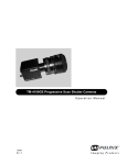
TM-4100CL Series Progressive Scan Shutter Cameras
Operation Manual
69-1199
Rev. B
See the Possibilities
Page ii
Page iii
Notice
The material contained in this manual consists of information that is proprietary to JAI, Inc., and may only be used by the purchasers of the product. JAI, Inc. makes no warranty for the use of its product and assumes no responsibility for any errors
which may appear or for damages resulting from the use of the information contained herein. JAI, Inc. reserves the right to
make changes without notice.
Microsoft, Windows XP, Windows 2000, Windows 98, Windows 95, Windows NT, and Windows Explorer are either registered trademarks or trademarks of Microsoft Corporation in the United States and/or other countries.
Warranty
All of our solid-state cameras sold in North America have a full three-year warranty. Those sold elsewhere have a full one-year
warranty. If any such product proves defective during the warranty period, JAI, Inc. will repair the defective product without
charge for parts and labor or will provide a replacement in exchange for the defective product. This warranty shall not apply to
any damage, defect or failure caused by improper use or inadequate maintenance.
Certifications
CE Compliance
The TM-4100CL series of cameras has been certified to conform to the requirements of Council Directive 89/336/EC for electromagnetic compatibility and to comply with the following European Standards:
Immunity:
Emissions:
EN50082-2/1997
CISPR22: 1997/EN55011: 1998 Class B
All PULNiX products bearing the CE mark have been declared to be in conformance with the applicable EEC Council Directives. However, certain factory-installed options or customer-requested modifications may compromise electromagnetic compatibility and affect CE compliance. Please note that the use of interconnect cables that are not properly grounded and shielded
may affect CE compliance.
Contact PULNiX Applications Engineering Department for further information regarding CE compliance.
FCC
UL
®
ST
I
A
SS
O CIA TI O
N
RM
FILE #
A3942
REG
MEMBER
FI
TED IM
MA
O
NG
GI
A
AU
T
This equipment has been tested and found to comply with the limits for a Class A digital device, pursuant to Part 15 of the
FCC Rules. These limits are designed to provide reasonable protection against harmful interference when the equipment is
operated in a commercial environment. This equipment generates, uses and can radiate radio frequency energy and, if not
installed and used in accordance with the instruction manual, may cause harmful interference to radio communications. Operation of this equipment in a residential area may cause harmful interference, in which case the user will be required to correct
the interference at his own expense.
ERED
JAI, INC.
ISO-9001
Page iv
WARNING
Changes or modifications to this unit not expressly approved by the party responsible for
FCC compliance could void the user’s authority to operate the equipment.
TM-4100CL Series Operation Manual
JAI, Inc.
625 River Oaks Parkway
San Jose, CA 95134
Tel:(408) 383-0300
Tel:(800) 445-5444
Fax:(408) 3283-0301
E-mail: [email protected]
www.jai.com
Page v
Table of Contents
TableofContents . . . . . . . . . . . . . . . . . . . . . . . . . . . . . . . . . . . . . . . . . . . . v
ListofFigures . . . . . . . . . . . . . . . . . . . . . . . . . . . . . . . . . . . . . . . . . . . . . . .vii
ListofTables . . . . . . . . . . . . . . . . . . . . . . . . . . . . . . . . . . . . . . . . . . . . . . . . x
1 Introduction . . . . . . . . . . . . . . . . . . . . . . . . . . . . . . . . . . . . . . . . . . 2
1.1
1.2
1.3
2
Product Description . . . . . . . . . . . . . . . . . . . . . . . . . . . . . . . . . . . . . . . . 2
Features . . . . . . . . . . . . . . . . . . . . . . . . . . . . . . . . . . . . . . . . . . . . . . . . 2
System Configuration . . . . . . . . . . . . . . . . . . . . . . . . . . . . . . . . . . . . . . 4
Installation
2.1
Getting Started
2.1.1
2.1.2
2.1.3
2.2
3
........................................... 5
........................................... 5
Unpacking Instructions . . . . . . . . . . . . . . . . . . . . . . . . . . . . . . . . . . . . . . . . . . .5
Components List . . . . . . . . . . . . . . . . . . . . . . . . . . . . . . . . . . . . . . . . . . . . . . . .5
Accessories and Options . . . . . . . . . . . . . . . . . . . . . . . . . . . . . . . . . . . . . . . . .5
Camera Setup
............................................ 5
2.2.1
2.2.2
2.2.3
2.2.4
2.2.5
2.2.6
Heat Dissipation . . . . . . . . . . . . . . . . . . . . . . . . . . . . . . . . . . . . . . . . . . . . . . . .5
Connector Pin Configurations . . . . . . . . . . . . . . . . . . . . . . . . . . . . . . . . . . . . . .6
Camera Link Cable . . . . . . . . . . . . . . . . . . . . . . . . . . . . . . . . . . . . . . . . . . . . . .7
Power Supplies and Power Cable Setup . . . . . . . . . . . . . . . . . . . . . . . . . . . . .8
Attaching the Analog Video Output
. . . . . . . . . . . . . . . . . . . . . . . . . . . . . . . .10
Attaching the Camera Lens . . . . . . . . . . . . . . . . . . . . . . . . . . . . . . . . . . . . . .10
Operation
. . . . . . . . . . . . . . . . . . . . . . . . . . . . . . . . . . . . . . . . . . 11
3.1.1
3.1.2
3.1.3
Digital I/O Connector (Camera Link)
. . . . . . . . . . . . . . . . . . . . . . . . . . . . . . . 11
Analog Output Connector . . . . . . . . . . . . . . . . . . . . . . . . . . . . . . . . . . . . . . . . 11
Power and External Sync Connector . . . . . . . . . . . . . . . . . . . . . . . . . . . . . . . 11
3.1
3.2
3.3
3.4
3.5
Camera Rear Panel
Progressive Scanning . . . . . . . . . . . . . . . . . . . . . . . . . . . . . . . . . . . . .
Electronic Shutter . . . . . . . . . . . . . . . . . . . . . . . . . . . . . . . . . . . . . . . .
Integration . . . . . . . . . . . . . . . . . . . . . . . . . . . . . . . . . . . . . . . . . . . . . .
Asynchronous Reset . . . . . . . . . . . . . . . . . . . . . . . . . . . . . . . . . . . . . .
3.5.1
3.5.2
3.6
3.8
3.9
. . . . . . . . . . . . . . . . .16
. . . . . . . . . . . . . . . . . . . . . . . . . . . . . . . . . . . . . . . . . . . . 16
Full Progressive Scan . . . . . . . . . . . . . . . . . . . . . . . . . . . . . . . . . . . . . . . . . . .16
Partial Scan . . . . . . . . . . . . . . . . . . . . . . . . . . . . . . . . . . . . . . . . . . . . . . . . . .16
External Sync and Pixel Locking . . . . . . . . . . . . . . . . . . . . . . . . . . . . . 17
Camera Timing Charts . . . . . . . . . . . . . . . . . . . . . . . . . . . . . . . . . . . . 18
3.9.1
Video Output Diagram
3.10 Serial Communication Kit
4
5
. . . . . . . . . . . . . . . . . . . . . . . . . . . . . . . . . . . 15
Programmable Look-Up Table (LUT) and Knee Control
Scan Modes
3.7.1
3.7.2
11
12
12
13
Internal Shutter Speed Control (TM-4100CL) . . . . . . . . . . . . . . . . . . . . . . . . .13
External VINIT With Pulse Width No-Delay Shutter and ROI (Read-out Inhibit)
(TM-4100CL) . . . . . . . . . . . . . . . . . . . . . . . . . . . . . . . . . . . . . . . . . . . . . . . . .14
Dynamic Range Control
3.6.1
3.7
. . . . . . . . . . . . . . . . . . . . . . . . . . . . . . . . . . . . . . 11
. . . . . . . . . . . . . . . . . . . . . . . . . . . . . . . . . . . . . . . . . .23
. . . . . . . . . . . . . . . . . . . . . . . . . . . . . . . . . . 24
TM-4100CL Command List . . . . . . . . . . . . . . . . . . . . . . . . . . . . . 25
Troubleshooting
. . . . . . . . . . . . . . . . . . . . . . . . . . . . . . . . . . . . . 27
5.1
Problems and Solutions
5.1.1
5.1.2
5.1.3
. . . . . . . . . . . . . . . . . . . . . . . . . . . . . . . . . . . 27
Symptom: No Video . . . . . . . . . . . . . . . . . . . . . . . . . . . . . . . . . . . . . . . . . . . .27
Symptom: Dark Video . . . . . . . . . . . . . . . . . . . . . . . . . . . . . . . . . . . . . . . . . . .27
Symptom: Non-synchronized Video . . . . . . . . . . . . . . . . . . . . . . . . . . . . . . . .27
Table of Contents
Page vi
5.2
6
7
Information and Support Resources
Appendix
. . . . . . . . . . . . . . . . . . . . . . . . . . . . . . . . . . . . . . . . . . . 29
6.1.1
6.1.2
TM-4100CL Physical Dimensions . . . . . . . . . . . . . . . . . . . . . . . . . . . . . . . . . 30
Spectral Response
. . . . . . . . . . . . . . . . . . . . . . . . . . . . . . . . . . . . . . . . . . . . 31
6.1
Specifications
Introduction
7.1
. . . . . . . . . . . . . . . . . . . . . . . . . . . . . . . . . . . . . . . . . 33
. . . . . . . . . . . . . . . . . . . . . . . . . . . . . . . . . . . . . . 33
Before Installing the Dual-Tap AccuPiXEL Series Camera-Control Software 33
Installing the Software . . . . . . . . . . . . . . . . . . . . . . . . . . . . . . . . . . . . . . . . . . 34
Installing the Camera Link API .dll (clserXXX.dll) . . . . . . . . . . . . . . . . . . . . . 35
Running Dual Tap AccuPiXEL . . . . . . . . . . . . . . . . . . . . . . . . . . . . . . . . . . . . 36
Uninstalling the Software . . . . . . . . . . . . . . . . . . . . . . . . . . . . . . . . . . . . . . . . 36
Verify the Camera is Connected . . . . . . . . . . . . . . . . . . . . . . . . . . . . . . . . . . 37
Graphical User Interface
8.1
8.2
8.3
8.4
8.4.2
8.4.3
8.4.4
8.4.5
8.4.6
8.4.7
8.4.8
. . . . . . . . . . . . . . . . . . . . . . . . . . . . . 42
Choose the desired mode from the mode screen when the dual-tap AccuPixel
camera control software starts: click the GO button. . . . . . . . . . . . . . . . . . . . 42
Check Current Camera Setting . . . . . . . . . . . . . . . . . . . . . . . . . . . . . . . . . . . 42
Exposure Control . . . . . . . . . . . . . . . . . . . . . . . . . . . . . . . . . . . . . . . . . . . . . . 42
Gain Control
. . . . . . . . . . . . . . . . . . . . . . . . . . . . . . . . . . . . . . . . . . . . . . . . . 45
Ref. Voltage . . . . . . . . . . . . . . . . . . . . . . . . . . . . . . . . . . . . . . . . . . . . . . . . . . 46
LUT (Look-Up Table) . . . . . . . . . . . . . . . . . . . . . . . . . . . . . . . . . . . . . . . . . . . 46
Video Depth . . . . . . . . . . . . . . . . . . . . . . . . . . . . . . . . . . . . . . . . . . . . . . . . . . 48
Report . . . . . . . . . . . . . . . . . . . . . . . . . . . . . . . . . . . . . . . . . . . . . . . . . . . . . . 48
Main Menu: “File”
8.5.1
8.5.2
8.5.3
8.6
8.7
8.8
CamLink Mode
. . . . . . . . . . . . . . . . . . . . . . . . . . . . . . . . . . . . . . . . . . . . . . . 40
GigE Mode . . . . . . . . . . . . . . . . . . . . . . . . . . . . . . . . . . . . . . . . . . . . . . . . . . . 41
Operating The Control Software
8.4.1
8.5
. . . . . . . . . . . . . . . . . . . . . . . . . . . . . . . 38
GUI Features
. . . . . . . . . . . . . . . . . . . . . . . . . . . . . . . . . . . . . . . . . . . 38
Starting Dual-Tap Accupixel Software . . . . . . . . . . . . . . . . . . . . . . . . . 39
Using the COM, CL, and GigE modes . . . . . . . . . . . . . . . . . . . . . . . . 39
8.3.1
8.3.2
. . . . . . . . . . . . . . . . . . . . . . . . . . . . . . . . . . . . . . . . 49
Load and Save Page . . . . . . . . . . . . . . . . . . . . . . . . . . . . . . . . . . . . . . . . . . . 49
Save Page . . . . . . . . . . . . . . . . . . . . . . . . . . . . . . . . . . . . . . . . . . . . . . . . . . . 49
Read Page . . . . . . . . . . . . . . . . . . . . . . . . . . . . . . . . . . . . . . . . . . . . . . . . . . . 50
Main Menu Option
. . . . . . . . . . . . . . . . . . . . . . . . . . . . . . . . . . . . . . . 50
Main Menu “Connectivity” . . . . . . . . . . . . . . . . . . . . . . . . . . . . . . . . . . 51
Main Menu “About” . . . . . . . . . . . . . . . . . . . . . . . . . . . . . . . . . . . . . . . 51
8.8.1
9
. . . . . . . . . . . . . . . . . . . . . . . . . . . . . . . . . . . . . . . . . . . 29
Software Installation
7.1.1
7.1.2
7.1.3
7.1.4
7.1.5
7.1.6
8
. . . . . . . . . . . . . . . . . . . . . . . . . . 28
Exit
. . . . . . . . . . . . . . . . . . . . . . . . . . . . . . . . . . . . . . . . . . . . . . . . . . . . . . . . . 53
Dual-Tap AccuPiXEL Series Camera Serial Commands
Table of Contents
. . . . . . . 54
Page vii
List of Figures
FIGURE 1.
CL (Camera Link) System Configuration
................................. 4
FIGURE 2.
3M Camera Link Cable
FIGURE 3.
12P-02S Interface Cable (optional)
FIGURE 4.
No-Delay Shutter
FIGURE 5.
No-Delay Shutter and Read-Out Inhibit
FIGURE 6.
Scan Modes
FIGURE 7.
Physical Dimensions
FIGURE 8.
Spectral Response
FIGURE 9.
The Setup icon installs Dual Tap AccuPIXel v 2.6.0
FIGURE 10.
AccuPIXel Setup screen
FIGURE 11.
Follow the installation directions
FIGURE 12.
Back of a dual-tap AccuPiXEL camera.
FIGURE 13.
Starting dual-tap AccuPiXEL from the desktop
FIGURE 14.
Initial Dual Tap AccuPiXEL screen.
. . . . . . . . . . . . . . . . . . . . . . . . . . . . . . . . . . . . 39
FIGURE 15.
Starting the Coyote screen grabber.
. . . . . . . . . . . . . . . . . . . . . . . . . . . . . . . . . . . 40
FIGURE 16.
Choose the desired frame driver DLL
FIGURE 17.
The error message if the .dll application is missing.
FIGURE 18.
The Report button provides camera setting information in the TX/RX frame.
FIGURE 19.
Manual and Async exposure control
FIGURE 20.
Exposure Control, Shutter Speed
FIGURE 21.
Select PWC from Shutter Speed in the Async mode.
FIGURE 22.
Scan Area options.
FIGURE 23.
Ref. Voltage slider
FIGURE 24.
Positive or Negative image
FIGURE 25.
The knee setting does not activate until the Send Knees button is clicked
FIGURE 26.
10-bit video output deactivates the LUT frame.
FIGURE 27.
Automatic camera report
.............................................. 8
..................................... 9
. . . . . . . . . . . . . . . . . . . . . . . . . . . . . . . . . . . . . . . . . . . . . . . . . . 14
. . . . . . . . . . . . . . . . . . . . . . . . . . . . . . . . . 15
. . . . . . . . . . . . . . . . . . . . . . . . . . . . . . . . . . . . . . . . . . . . . . . . . . . . . . 16
. . . . . . . . . . . . . . . . . . . . . . . . . . . . . . . . . . . . . . . . . . . . . . . 30
. . . . . . . . . . . . . . . . . . . . . . . . . . . . . . . . . . . . . . . . . . . . . . . . 31
. . . . . . . . . . . . . . . . . . . . . . . 34
. . . . . . . . . . . . . . . . . . . . . . . . . . . . . . . . . . . . . . . . . . . . 35
. . . . . . . . . . . . . . . . . . . . . . . . . . . . . . . . . . . . . . 35
. . . . . . . . . . . . . . . . . . . . . . . . . . . . . . . . . 37
. . . . . . . . . . . . . . . . . . . . . . . . . . . 39
. . . . . . . . . . . . . . . . . . . . . . . . . . . . . . . . . . 41
. . . . . . . . . . . . . . . . . . . . . . . 41
. . . . 42
. . . . . . . . . . . . . . . . . . . . . . . . . . . . . . . . . . . 42
. . . . . . . . . . . . . . . . . . . . . . . . . . . . . . . . . . . . . 43
. . . . . . . . . . . . . . . . . . . . . . 44
. . . . . . . . . . . . . . . . . . . . . . . . . . . . . . . . . . . . . . . . . . . . . . . . 44
. . . . . . . . . . . . . . . . . . . . . . . . . . . . . . . . . . . . . . . . . . . . . . . . . 46
. . . . . . . . . . . . . . . . . . . . . . . . . . . . . . . . . . . . . . . . . . 46
. . . . . . 47
. . . . . . . . . . . . . . . . . . . . . . . . . . . 48
. . . . . . . . . . . . . . . . . . . . . . . . . . . . . . . . . . . . . . . . . . . . 48
List of Figures
Page viii
FIGURE 28.
Load Page
. . . . . . . . . . . . . . . . . . . . . . . . . . . . . . . . . . . . . . . . . . . . . . . . . . . . . . . 49
FIGURE 29.
Save Page
. . . . . . . . . . . . . . . . . . . . . . . . . . . . . . . . . . . . . . . . . . . . . . . . . . . . . . . 50
FIGURE 30.
Video output order
FIGURE 31.
Buffer Size
FIGURE 32.
Camera Model
FIGURE 33.
CPU Firmware Version
List of Figures
. . . . . . . . . . . . . . . . . . . . . . . . . . . . . . . . . . . . . . . . . . . . . . . . . 51
. . . . . . . . . . . . . . . . . . . . . . . . . . . . . . . . . . . . . . . . . . . . . . . . . . . . . . . 51
. . . . . . . . . . . . . . . . . . . . . . . . . . . . . . . . . . . . . . . . . . . . . . . . . . . . 52
. . . . . . . . . . . . . . . . . . . . . . . . . . . . . . . . . . . . . . . . . . . . . . 52
Page ix
List of Tables
TABLE 1.
12-Pin Connector
............................................ 6
TABLE 2.
Connector and Pin-out Configurations
TABLE 3.
TM-4100CL Command List
TABLE 4.
TM-4100CL Camera Specifications Table
............................ 7
. . . . . . . . . . . . . . . . . . . . . . . . . . . . . . . . . . . 25
. . . . . . . . . . . . . . . . . . . . . . . . 29
List of Tables
Page x
List of Tables
May 1, 2007
TM-4100CL Series Progressive
Scan Shutter Cameras
Operation Manual
1
Introduction
1.1 Product Description
The PULNiX TM-4100CL series1 consists of dual-tap output, high-resolution, high-speed monochrome
progressive scan CCD cameras. 2The interline-type CCD permits full vertical and horizontal resolution
of very high speed shutter images and applications. The electronic shutter, which has speeds to 1/16,000
sec., can be reset asynchronously by external pulse control. The frame rate is 15 fps. A square imager
format with uniform square pixels provides superior image definition in any orientation. On-chip micro
lenses provide increased sensitivity.
The TM-4100CL has a full dynamic range control function, which can be set at externally selectable
look-up table (LUT)3 knee slopes to convert 10-bit input to 8-bit output, thereby optimizing the CCD’s
full dynamic range in the normal output signal range. As dual-tap outputs camera, the TM-4100CL has
dual-channel auto-block level balancing and auto-gain balancing functions. The camera has a dual-tap,
10-bit or 8-bit Camera Link output. All the key functions are controlled via Camera Link serial
communication interface.
Multi-camera operation requires synchronized data and clock phases from each camera as a standard
feature. The TM-4100CL has a phase lock loop (PLL) to synchronize on external horizontal drive (Hd)
for multi-camera operation that is offered as standard.
1. The TM-4100CL is available with either 8-bit processing or 10-bit processing. You must specify
your choice of configurations when you purchase the camera.
2. The TM-4100CL series consists of the TM-4100CL (monochrome), RM-4100CL (monochrome
RoHS), the TMC-4100CL (color), and the RMC-4100CL (color RoHS). Unless otherwise noted,
all information contained in this manual is relevant to both models.
3. The TM-4100CL 8-bit output camera has an LUT, which is not included on the 10-bit camera.
TM-4100CL Series Progressive Scan Shutter Cameras
Page 2
TM-4100CL Series Progressive Scan Shutter Cameras
Applications for the TM-4100CL include machine vision, medical imaging, intelligent transportation
systems, high-definition graphics, on-line inspection, gauging, character reading, archiving, and highsecurity surveillance.
1.2 Features
•
Miniature size and light weight
The printed circuit boards in the TM-4100CL have been arranged based on a new design
philosophy. This creates modular electronics for the camera, giving it flexibility. In addition, the
use of miniature solid-state components results in a compact, lightweight camera that is 50.8mm x
50.8mm x 81.5mm in dimensions, and weighs only 155 grams.
•
Imager
The TM-4100CL uses a dual-tap progressive-scan interline transfer CCD that has the following
features:
- Resolution of 2048 x 2048 active pixels for excellent image quality.
- 7.4 x 7.4 µm square pixels for precise dimensional measurement.
- High-speed electronic shutter capability for high dynamic resolution of moving objects that
eliminates the need for a mechanical shutter.
- Progressive-scan CCD eliminates interlace deterioration of image and increases ease of
computer interface.
- High sensitivity and low noise at fast scanning. The CCD has an excellent S/N ratio that is
greater than 48dB.
- The CCD has a built-in microlens for increased quantum efficiency.
•
Electronic shutter
The TM-4100CL has a substrate drain-type shutter mechanism which provides superb pictures at
various speeds without smearing. For more information, please see Section 3.3, “Electronic
Shutter,” on page 11.
•
Asynchronous reset
The TM-4100CL captures async reset images and provides single-shot video output with single
FDV. This makes it simpler for an ordinary framegrabber to capture the async reset images. The
TM-4100CL’s asynchronous reset is flexible and accepts external horizontal drive (HD) for phase
locking. When the VINIT (5V) pulse is applied to CC1, it resets the camera's scanning and purging
of the CCD.
The TM-4100CL has two modes to control the asynchronous reset and shutter speed:
- External VINIT with pulse width. The duration between pulse edges controls the shutter
speed externally.
- Internal shutter speed control. The speed control varies from 1/125 to 1/16,000 sec. The
video signal and FDV starts with internal V reset timing related to shutter speed.
Introduction
Page 3
TM-4100CL Series Progressive Scan Shutter Cameras
•
Output
The TM-4100CL has a dual tap 10-bit or 8-bit Camera Link output. The analog output is
714 mVp-p composite video (75 ohms) on all models.
•
Dual-Channel Auto Black Level Balancing and Auto Gain
The TM-4100CL, as a dual-tap output camera, has dual-channel auto black level balancing and
auto gain balancing functions.
•
Integration
The TM-4100CL is capable of capturing high-resolution integration images. Its CCD imager can be
exposed for longer than the normal scan timing of 1/15 sec. This integration feature provides extra
sensitivity for applications in dark environments. The progressive scan imager permits a full frame
of resolution in non-interlace format. Integration is achieved by applying INTEG signal to CC2
control of Camera Link or by feeding VINIT pulse width control up to 1 sec of the pulse width in
async pulse width control mode for the frames to be integrated.
•
Warranty
Please contact your factory representative for details about the warranty.
1.3 System Configuration
FIGURE 1.
CL (Camera Link) System Configuration
Figure 1 below presents a typical system configuration for the Camera Link version.
26CL-02-26
CAMERA LINK
1
Power and
Ext. Sync
12P-02S
2
3
9
8
10
11
4
7
12
5
POWER
6
VIDEO
or
PD-12P (series)
power supply
Computer with
Camera Link™
frame grabber
Introduction
Page 4
TM-4100CL Series Progressive Scan Shutter Cameras
2
Installation
The following instructions are provided to help you to set up your camera quickly and easily. We
suggest that you read through these instructions before you unpack and set up your camera system.
2.1 Getting Started
2.1.1
Unpacking Instructions
We recommend that you save the original packing cartons for the cameras and accessories in case you
need to return or exchange an item.
We also recommend that you bench-test any equipment being sent to another location for field
installation to assure that everything is fully operational as a system.
2.1.2
Components List
Please begin by checking your order against the Components List shown below to assure that you have
received everything as ordered, and that nothing has been overlooked in the packing materials. If any
item is missing, please contact your PULNiX representative immediately.
•
TM-4100CL camera
•
Camera-specific data sheet
•
Camera-appropriate operation manual (if ordered)
•
Dual-tap AccuPiXEL camera-control software
2.1.3
Accessories and Options
Following is a list of additional accessories and options that may be required for your application.
Please check with your PULNiX representative before you install your camera to determine what you
might need.
•
PD-12U series power supply
•
12P-02S power cable
•
26CL-02-26 Camera Link cable
2.2 Camera Setup
2.2.1
Heat Dissipation
The TM-4100CL is a compact 2K by 2K camera. Since all the electronics have been packed in a
compact package, the outer case of the camera can become hot due to heat dissipation. For optimal
performance, PULNiX recommends using a cooling fan to set up a positive air flow around the camera
and following the precautions below.
Installation
Page 5
TM-4100CL Series Progressive Scan Shutter Cameras
•
Mount the camera on a large heat sink (camera bracket) made out of heat-conductive material like
aluminum.
•
Make sure the flow of heat from the camera case to the bracket is not blocked by a non-conductive
material like plastic.
•
Make sure the camera has enough open space around it to facilitate the free flow of air.
Please contact JAI, Inc. at (800) 445-5444 or send an E-mail to [email protected] if you have any
questions.
2.2.2
Connector Pin Configurations
2.2.2 (a)
12-Pin Connector
The TM-4100CL has a 12-pin Hirose connector for power input and signal integration. Pin #1 is Ground
and pin #12 is +12V DC. The pin-out table is shown below. Serial communication camera control is
done via the Camera Link connector on the rear panel of the camera.
TABLE 1.
12-Pin Connector
Pin
1
Description
Pin
Description
1
GND
7
NC/VD in*
2
+12V DC
8
Strobe
3
GND (analog)
9
NC/HD in*
4
Video out
10
NC/RXD (RS-232)a
5
GND (digital)
11
NC/Integration Control*
6
NC/VINIT in*
12
NC/TXD (RS-232)*
2
3
9
11
4
8
10
7
12
5
6
a. Option
2.2.2 (b)
Digital I/O Connector
The TM-4100 has a 26-pin connector on the rear panel to output Camera Link data. The connector pinout is shown in Table 2 on page 6.
13
26
1
14
Installation
Page 6
TM-4100CL Series Progressive Scan Shutter Cameras
TABLE 2.
Connector and Pin-out Configurations
Camera Link Connector
Pin
#
Description
1
GND
2
Tx OUT 0-
3
I/O
Pin
#
Description
I/O
14
GND
Out
15
Tx OUT 0+
Out
Tx OUT 1-
Out
16
Tx OUT 1+
Out
4
Tx OUT 2-
Out
17
Tx OUT 2+
Out
5
Tx CLK OUT -
Out
18
Tx CLK OUT+
Out
6
Tx OUT 3-
Out
19
Tx OUT 3+
Out
7
SerTC+
In
20
SerTC-
In
8
SerTFG-
Out
21
SerTFG+
Out
9
VINIT- /CC1-
In
22
VINIT+
In/CC1+
10
INTEG+/CC2+
In
23
INTEG-
In/CC2-
11
EX-HD-/CC3-
In
24
EX-HD+
In/CC3+
12
EX-VD+/CC4+
In
25
EX-VD-
In/CC4-
13
GND
26
GND
Note:SerTC: Serial To Camera
SerTFG: Serial to framegrabber
2.2.2 (c)
Analog Output Connector
The TM-4100CL has a BNC connector on the rear panel to output analog
video signal (Channel “A” only at 40 MHz). Analog output is available to
drive auto-iris lenses and troubleshooting only. Analog output is not
suitable for monitors or fame grabbers.
2.2.3
Camera Link Cable
The 26CL-02-26 cable assembly has been standardized as the Camera Link cable. This cable has a 26pin connector on both ends. This is a straight-through cable and the pin-out configuration is shown in
Table 2 on page 6. Contact PULNiX for cable lengths other than 2 meters.
Installation
Page 7
TM-4100CL Series Progressive Scan Shutter Cameras
3M Camera Link Cable
2
16
3
17
4
18
5
19
6
20
7
21
8
22
9
23
10
24
11
25
12
26
13
11
24
23
8
21
20
6
19
5
3
16
2
15
1
4
18
7
9
10
12
13
15
25
1
22
14
2X
Thumbscrews
26
26 Position
High Density
Mini D Ribbon
(MDR) Male Plug
Cable
17
26 Position
High Density
Mini D Ribbon
(MDR) Male Plug
14
FIGURE 2.
2X
Thumbscrews
Note:For CL versions, serial communication for camera control is done via the Camera Link
connector on the rear panel of the camera.
2.2.4
2.2.4 (a)
Power Supplies and Power Cable Setup
Power Supplies
The TM-4100CL camera requires 12V DC power that is obtained through the 12-pin connector located
on the rear panel of the camera. PULNiX recommends the following power supplies:
PD-12UU
100-240V AC/12V DC
1.2A universal voltage power supply,
US Plug
PD-12UUP
PD-12UU with12-pin connector
US plug
PD-12UE
PD-12UU
European plug
PD-12UEP
PD-12UU with 12-pin connector
European plug
For users providing power through the 12-pin connector, the PD-12P, PD-12UEP and PD-12UUP
power supplies are available with the 12-pin mating connector already attached to the leads from the
power supply. The PD-12UU and PD-12UE power supplies can be connected to the PULNiX power
cable via a terminal strip or directly.
When wiring the PD-12UU and PD-12UE power supplies directly, please note the following:
•
The lead ends must be twisted together and tin-soldered for strength and electrical continuity.
•
Shrink tubing or a similar insulator should be used to prevent exposed leads from touching and
shorting.
•
The +12V lead is marked with a red stripe or white lettering; be sure not to reverse the leads.
•
All connections must be properly insulated to prevent shorting.
Installation
Page 8
TM-4100CL Series Progressive Scan Shutter Cameras
2.2.4 (b)
PULNiX Power Cables
If you are using PULNiX power cables such as the 12P-02S, please refer to the 12-pin connector pin-out
diagram below. The cable pin-out diagram is shown in Figure 3 below. The color-coded leads use Gray
for Ground and Yellow for +12V.
12P-02S Interface Cable (optional)
FIGURE 3.
+12 V
GND (Gray)
Power (Yellow)
Video Out (Red Coax)
HD In (White Coax)
VD In (Black Coax)
Male
Analog Ch. A only
}
External sync input
12P-02S Interface Cable
Pin#
Lead Color
Function
Pin#
Lead Color
Function
1
Gray
GND
7
Black coax
VD Input*
2
Yellow
+12V DC
8
White coax shield
Strobe out
3
Red coax shield
(analog)
9
White coax
HD Input*
4
Red coax
Video Out
10
Brown
RXD (RS-232)*
5
Orange coax shield
(digital)
11
Blue
Integration*
6
Orange coax
VINIT INa
12
Black coax shield
TXD (RS-232)*
a. Optional
Note: Make sure that the unused leads are not touching and that there is no possibility that exposed
wires could cause the leads to short.
2.2.4 (c)
Building Your Own Power Cable
Refer to the 12-pin connector pin-out in Figure 3 on page 8. Connect the Ground lead to pin #1, and the
+12V DC lead to pin #2 of the 12-pin connector. Power must be DC-regulated, and of sufficient current
to properly power the camera.
2.2.4 (d)
Attaching the Power Cable to the Connector
The 12-pin connector is keyed and will only fit in one orientation. Follow these directions to properly
attach the power cable to the camera connector:
1.
Rotate the connector while applying slight pressure until the keyways line up.
2.
Press the connector into place until firmly seated.
3.
Plug the power cord into the 100V AC socket. This will power the camera up.
Installation
Page 9
TM-4100CL Series Progressive Scan Shutter Cameras
2.2.5
Attaching the Analog Video Output
When connecting the TM-4100CL to an analog framegrabber or a monitor, use the BNC connector on
the rear panel of the camera. The input of the monitor should be balanced for 75 ohms termination.
Standard RG-59 type coaxial cable should carry a full video signal for up to 500 feet. The TM-4100CL
has a two-row binning mode that can be used to display real-time images on PULNiX’s PVM-942 or
PVM-1242 monitors. These monitors are specially modified to accept a 30Hz progressive scan image.
The multi-conductor cable 12P-02S from PULNiX can be used to transmit analog video, power, sync.
signals, and serial communication. The mini coaxial leads in PULNiX multi-conductor cables are
designed for short runs of no longer than 50 feet.
Note: Make sure that no extraneous wires are visible which could cause a short.
2.2.6
Attaching the Camera Lens
The TM-4100CL camera accepts 1.2" or larger format size C-mount lenses. To attach the C-mount lens1
to the camera, carefully engage the threads and rotate the lens clockwise until it firmly seats on the
mounting ring. Do not force the lens if it does not seat properly. Please note that some lenses with
extremely long flangebacks may exceed the mounting depth of the camera.
1. C-mount to F-mount and C-mount to K-mount adapters are available for larger format lenses
(35mm). Check with local photography dealers for these lens adapters.
Installation
Page 10
TM-4100CL Series Progressive Scan Shutter Cameras
3
Operation
3.1 Camera Rear Panel
CAMERA LINK
1
2
3
9
11
4
8
10
7
12
5
6
POWER
3.1.1
VIDEO
Digital I/O Connector (Camera Link)
Refer to Section 2.2.3 on page 6 for information on digital output connectors.
3.1.2
Analog Output Connector
The camera has a BNC connector on the rear panel to output analog video signal.
3.1.3
Power and External Sync Connector
Refer to Section 2.2.2 (b on page 5 for information on the power and external sync. connectors.
3.2 Progressive Scanning
Standard TV-system scanning is 525 lines interlace scanning as specified in the RS-170 protocol. Every
other horizontal line (odd lines and even lines) is scanned at a 60Hz rate per field, and the scanning is
completed with two fields (one frame) at 30Hz rate. Because of the interlace scanning, the vertical
resolution of CCD cameras is limited at 350 TV lines, regardless of the horizontal resolution. When
electronic shutter is applied, the CCD can hold only one field of charge at each exposure. This means
that the vertical resolution of the electronic-shutter camera is only 244 TV lines. The situation is the
same for an HDTV-format camera, since it has interlaced scanning and the vertical resolution of the
shuttered image is 500 lines.
The TM-4100CL uses a state-of-the-art progressive scanning interline transfer CCD which scans all
lines sequentially from top to bottom at one frame rate. Like a non-interlace computer screen, it
generates a stable, crisp image without alternating lines and provides full vertical TV resolution of 1000
lines (a normal TV monitor display may not be able to show 1000 lines due to monitor resolution of
30Hz scanning).
Operation
Page 11
TM-4100CL Series Progressive Scan Shutter Cameras
The interline transfer architecture is also important to generate simultaneous shuttering. This is different
from full frame transfer architecture which requires a mechanical shutter or strobe light in order to
freeze the object motion.
The TM-4100CL outputs the progressive-scanned image with an electronic shutter in two different
formats:
1.
Progressive-scanning digital and analog output
The CCD signal goes through A/D and D/A converters and through 10-bit in, 10-bit or 8bit out look-up table (LUT).
The analog output is the same as 75 ohms, 714m Vp-p format available from BNC and
12-pin connector. The digital output is available via the Camera Link connector.
2.
Partial Scan Mode
By selection, the camera has centered 1000 lines, 500 lines, and 250 lines. Partial scan
mode, 1000 lines, partial scan’s frame rate is 28fps. 500 lines is 50 fps, 250 lines is 80
fps.
3.3 Electronic Shutter
The TM-4100CL has a substrate drain-type shutter mechanism which provides a superb picture at
various speeds without smearing. A built-in manual shutter speed control selects the electronic shutter
rate of 1/60 (non-async mode only), 1/125, 1/250, 1/500, 1/1,000, 1/2,000, 1/4,000, 1/8,000, or 1/16,000
second.
With VINIT high (5V), the CCD keeps discharging. With a negative pulse to VINIT, the camera resets
and purges the charge momentarily. Then it starts integrating for the period of shutter control set by
either an external pulse width or internal shutter control. Progressive scanning permits a full 1000 lines
of vertical resolution, as compared to a conventional CCD camera which captures only half the vertical
lines per shutter.
3.4 Integration
The CCD imager of the TM-4100CL can be exposed for longer than the normal scan timing of 1/15 sec.
This integration feature provides extra sensitivity for dark-environment applications. The progressivescan imager permits a full frame of resolution in non-interlace format. Integration is achieved by
controlling CC2 Camera Control line through the Camera Link cable to low (GND) or providing pulsewidth control up to 1/15 frames. Please refer to Figure 2.2.2 on page 5 for pin-out information on the
12-pin connector.
Operation
Page 12
TM-4100CL Series Progressive Scan Shutter Cameras
3.5 Asynchronous Reset
ASYNC RESET
VINIT
VD
SG (TRANSFER GATE)
DISCHARGE PULSE
FDV
PROGRESSIVE OUTPUT
VIDEO
Stand-by Image
Shutter Video
Stand-by Image
The TM-4100CL camera includes two modes to control the asynchronous reset and shutter speed:
•
Internal Shutter Speed Control
•
External VINIT with Pulse Width
3.5.1
Internal Shutter Speed Control (TM-4100CL)
EXT. VINIT
HD
INT. VINIT with shutter speed control
Discharge
Exposure time set by shutter speed
Transfer Gate
Strobe
FDV
Analog Video Sync
The video signal starts with internal VINIT. The camera operates the reset and shutter in the same way
as the external pulse width control mode. When the external VINIT pulse is applied, internal VINIT is
latched to HD and the internal VINIT is delayed to set up the shutter speed period. The shutter speed is
controlled by communication software from “1” to “8.” Video output timing starts right after the
internal VINIT and single shots, FDV is output at the internal VINIT timing.
Operation
Page 13
TM-4100CL Series Progressive Scan Shutter Cameras
3.5.2
External VINIT With Pulse Width No-Delay Shutter and ROI (Read-out
Inhibit) (TM-4100CL)
For multiple-camera applications such as 2D or 3D measurement and multi-angle inspection,
simultaneous image capturing at an exact shutter timing for all cameras is a critical requirement. The
TM-4100CL’s asynchronous pulse-width control mode provides no-delay shutter as standard.
Regardless of the internal pulse timing, the camera discharges at the VINIT leading edge and transfers
charges at the trailing edge of the pulse. Even though each camera runs with slightly different H and
data clock timing, the image capturing is exactly simultaneous.
FIGURE 4.
No-Delay Shutter
HD
INT. VINIT after trailing edge of EXT. VINIT
Discharge
Exposure time set by pulse width
Transfer Gate
Strobe
FDV
Analog Video Sync
Vsync
The TM-4100CL camera also has read-out-inhibit control (ROI) to control the vertical clock start
(Async Shutter #9). When ROI is low, V-clock is stopped and the transferred charges remain in the
vertical shift registers, which work like CCD memory. When the ROI is high, it clocks out the CCD
data. This helps a single framegrabber process multiple images in pipeline processing (sequential
process).
Note: When the ROI function is not used, make sure that the INTEG/ROI CCL input is kept logic
high during Async. pulse width control mode.
Operation
Page 14
TM-4100CL Series Progressive Scan Shutter Cameras
FIGURE 5.
No-Delay Shutter and Read-Out Inhibit
VINIT (External Pulse Width Control Trigger)
No-Delay Shutter (All cameras)
Discharge
No-delay Exposure
Transfer Gate
ROI pulse width: Min. 1H to 1frame
ROI Control: Camera #1
Camera #1 Video
FDV/Vsync
Max. 1H delay
ROI Control: Camera #2
Camera #2 Video
3.6 Dynamic Range Control
Blooming adj. = 13. 5 V
Lens: F=5.6
mV
Vsub = 8 V
Max. Digital dynamic range at 3 dB amp
600
CCD OUTPUT VOLTAGE
Vsub = 10 V
Vsub = 12 V
400
Vsub = 14 V
Vsub = 16 V
200
Digital saturation at 16 dB amp
Vsub = 18 V
Analog saturation at 20 dB amp
0
0
20
40
60
80
LUMINANCE
100
120
140
160
FL
The typical interline transfer CCD has fixed noise levels based on dark current (thermal or KT noise),
pattern noise, and the operating clock speed. In general, the level of the 20 MHz pixel clock CCD at
room temperature is around 20 to 50 electrons. The maximum capacity of CCD charges is limited by the
well capacity at saturation. The range is limited by the structure and the pixel size.
The TM-4100CL uses a CCD with 7.4 µm x 7.4 µm pixel and two-phase vertical shift register structure.
The well capacity is 40,000 electrons. The theoretical dynamic range is 40,000:30 = 1333:1 (60 dB).
Operation
Page 15
TM-4100CL Series Progressive Scan Shutter Cameras
A typical CCD camera does not use the full dynamic range due to the nominal gain and the output
specification such as RS-170. The typical CCD camera’s gain is set at 16 to 22 dB and the RS-170 video
level is 714 mV. Using 20 dB gain for the calculation, CCD output is limited to 714/10 = 71.4 mV.
Since the CCD’s saturation voltage is 400 mV to 500 mV, it uses less than 1/5 of the full dynamic range.
Machine vision and outdoor applications, cannot afford to miss image information behind the
saturation, which is why the dynamic range adaptation is critical.
3.6.1
Programmable Look-Up Table (LUT) and Knee Control
The TM-4100CL has a built-in LUT (look-up table) for dynamic range control.
At a specific gain setting, the offset (minimum level.... dark point) and A/D reference top voltage
(maximum level... saturation point) are set to 10-bit A/D input so that the full dynamic range of the
CCD is utilized at 10-bit references as the input and the LUT output is converted into 8-bit to adjust the
gamma correction.
The look-up table has two knee points (variable gamma selection) that allow the 10-bit input to be
segmented into three regions. The look-up table selection can be made by knee curve direct input.
3.7 Scan Modes
The TM-4100CL supports the following scan modes:
FIGURE 6.
Scan Modes
line 1
line 2
n
n+1
3.7.1
Center
1000, 500, 250
Full Progressive Scan
Normal scanning mode the TM-4100CL is for 2048 x 2048 pixels. The standard speed with dualchannel output is 15 frame/sec at the pixel clock of 40 MHz. The progressive scan reads every line from
top to bottom and, unique in an interlace-scan camera, all lines are obtained per image capturing with
electronic shutter.
3.7.2
Partial Scan
TM-4100CL has centered 1000 lines, 500 lines and 250 lines partial scan mode.
Operation
Page 16
TM-4100CL Series Progressive Scan Shutter Cameras
3.8 External Sync and Pixel Locking
The TM-4100CL accepts an external sync of standard HD and VD at TTL level for general locking to a
system sync and clock.The frequency requirement is as follows:
Full Progressive Scan:
fHD = 30.769 KHz ± 2%
fVD = 14.79 Hz ± 2%
(Internal Master clock = 80.00 MHz,
Pixel clock = 40.00 MHz)
100L Partial Scan:
fHD = 30.769 KHz ± 2%
fVD = 27.97 Hz ± 2%
500L Partial Scan:
fHD = 30.769 KHz ± 2%
fVD = 49.63 Hz ± 2%
250L Partial Scan:
fHD = 30.769 KHz ± 2%
fVD = 79.92 Hz ± 2%
Note: The external sync is not available in two-row binning.
Operation
Page 17
TM-4100CL Series Progressive Scan Shutter Cameras
3.9 Camera Timing Charts
Model: TM-4100
Operation Mode: Dual Tap Output
Master Clock: 80.000 MHz, M=12.5 nsec
Pixel Clock: 40.000 MHz, P= 25.0 nsec
1. Pixel Clock and Digital Data
Pixel Clock
A
Data
Tcd
Tdc
Thd
Tcd: Clock to Data Ready
Tdc: Data Ready to Next Clock
Thd: Data Hold Time
Tcd = 12.5 nsec, Tdc = 12.5 nsec, Thd = 7 nsec.
2. Horizontal Signals Timing
fHD = [ 30.78 KHz]
tHD = [ 32.5 µsec]
External HD
A [ 100 P],( 2.50 µs)
Internal HD
B [ 1200 P], ( 30.0 µs)
C [ 1300 P], ( 32.5 µs)
LDV
G [ 0 P], ( 0.0 µs)
D [ 276 P], ( 6.90 µs)
E [ 1024 P], ( 25.6 µs)
F [ 1300 P], ( 32.5 µs)
Digital Data
I [ 1024 P], ( 25.6 µs)
H [ 276 P], ( 6.9 µs)
Analog Video
N [ 100 P], ( 2.50 µs)
K [ 1024 P], ( 25.6 µs)
J [ 176 P], ( 4.40 µs)
M [ 100 P], ( 2.50 µs)
L [ 100 P], ( 2.50 µs)
Operation
Page 18
TM-4100CL Series Progressive Scan Shutter Cameras
Model: TM-4100
Operation Mode: Dual Tap Output
Full Scan
14.79 Frames/second
Master Clock: 80.000 MHz, M= 12.5 nsec
Pixel Clock: 40.000 MHz, P= 25.0 nsec
3. External Reset Timing and Vertical Signals Timing
External VD
A [ 2080 H], (67.6 msec)
B [ <1 H], ( <32.5 µs)
C [ 9 H], (0.29 ms)
Internal VD
D [ 2071 H], ( 67.3 ms)
E [ 2080 H], ( 67.6 ms)
G [ 32 H], ( 1.04 ms)
FDV
H [ 2048 H], ( 66.56 ms)
F [ 1 H], ( 32.5 µs)
J [ 32 H], ( 1.04 ms)
Digital Data
K [ 2048 H], ( 66.56 ms)
M [ 29 H], ( 0.94 ms)
Analog Video
L [ 3H], ( 97.5 µs)
N [ 3H], ( 97.5 µs)
O [ 2048 H], ( 66.56 ms)
P [ 3H], ( 97.5 µs)
4. Async Reset Timing
VINIT Trigger
Q: Internal VD Shift = 1H + async shutter speed / VINIT pulse width
Q [Variable], ( µs)
R [ 9 H], ( 0.29 ms)
Internal VD
S [ 2071 H], ( 67.3 ms)
T [ 2080 H], ( 67.6 ms)
FDV
V [ 33 H], ( 1.0725 ms)
Digital Data
X [ 33 H], ( 1.0725 ms)
W [ 2048 H], ( 66.56 ms)
AA [ 29 H], (0.94 ms)
Y [ 2048 H], ( 66.56 ms)
Analog Video
Z [ 4H], ( 130 µs)
Strobe
Operation
CC [ 2048 H], ( 66.56 ms)
Page 19
TM-4100CL Series Progressive Scan Shutter Cameras
Model: TM-4100
Operation Mode: Dual Tap Output
Centered 1000Ls PS
27.97 Frames/second
Master Clock: 80.000 MHz, M= 12.5 nsec
Pixel Clock: 40.000 MHz, P= 25.0 nsec
5. External Reset Timing and Vertical Signals Timing
External VD
A [ 1100 H], ( 35.75 msec)
C [ 9 H], (0.29 ms)
B [ <1 H], ( <32.5 µs)
Internal VD
D [ 1091 H], ( 35.4575 ms)
E [ 1100 H], ( 35.75 ms)
G [ 100H], ( 3.25 ms)
FDV
H [ 1000 H], ( 32.5 ms)
F [ 1 H], ( 32.5 µs)
J [ 100H], ( 3.25 ms)
Digital Data
K [ 1000 H], ( 32.5 ms)
M [ 97 H], ( 3.1525 ms)
Analog Video
O [ 1000 H], ( 32.5 ms)
L [ 3H], ( 97.5 µs)
P [ 3H], ( 97.5 µs)
N [ 3H], ( 97.5 µs)
6. Async Reset Timing
VINIT Trigger
Q: Internal VD shift = 1H + async shutter speed / VINIT pulse width
Q [Variable], ( µs)
R [ 9 H], ( 0.29 ms)
Internal VD
S [ 1091 H], ( 35.4575 ms)
T [ 1100 H], ( 35.75 ms)
V [ 101 H], ( 3.2825 ms)
Digital Data
W [ 1000 H], ( 32.5 ms)
X [ 101 H], ( 3.2825 ms)
Y [ 1000 H], ( 32.5 ms)
AA [ 97 H], ( 3.1525 ms)
Analog Video
Z [ 4H], ( 130 µs)
CC [ 1000 H], ( 32.5 ms)
BB [ 3 H], ( 97.5 µs)
Strobe
Operation
Page 20
TM-4100CL Series Progressive Scan Shutter Cameras
Model: TM-4100
Operation Mode: Dual Tap Output
Centered 500Ls PS
49.63 Frames/second
Master Clock: 80.000 MHz, M= 12.5 nsec
Pixel Clock: 40.000 MHz, P= 25.0 nsec
7. External Reset Timing and Vertical Signals Timing
External VD
A [ 620 H], ( 20.15 msec)
C [ 9 H], (0.29 ms)
B [ <1 H], ( <32.5 µs)
Internal VD
D [ 611 H], ( 19.8575 ms)
E [ 620 H], ( 20.15 ms)
G [ 120H], ( 3.90 ms)
FDV
F [ 1 H], ( 32.5 µs)
H [ 500 H], ( 16.25 ms)
J [ 120H], ( 3.90 ms)
Digital Data
K [ 500 H], ( 16.25 ms)
M [ 117 H], ( 3.8025 ms)
Analog Video
O [ 500 H], ( 16.25 ms)
L [ 3H], ( 97.5 µs)
P [ 3H], ( 97.5 µs)
N [ 3H], ( 97.5 µs)
8. Async Reset Timing
Q: Internal VD shift = 1H + async shutter speed / VINIT pulse width
Q [Variable], ( µs)
VINIT Trigger
R [ 9 H], ( 0.29 ms)
Internal VD
S [ 611 H], ( 19.8575 ms)
T [ 620 H], ( 20.15 ms)
V [ 121 H], ( 3.9325 ms)
FDV
Digital Data
W [ 500 H], ( 16.25 ms)
X [ 121 H], ( 3.9325 ms)
Y [ 500 H], ( 16.25 ms)
AA [ 117 H], ( 3.8025 ms)
Analog Video
CC [ 500 H], ( 16.25 ms)
Z [ 4H], ( 130 µs)
BB [ 3 H], ( 97.5 µs)
Strobe
Operation
Page 21
TM-4100CL Series Progressive Scan Shutter Cameras
Model: TM-4100
Operation Mode: Dual-Tap Output
Centered 250Ls PS
79.92 Frames/second
Master Clock: 80.000 MHz, M=12.5nsec
Pixel Clock: 40.000 MHz, P= 25.0 nsec
9. External Reset Timing and Vertical Signals Timing
External VD
A [ 385 H], ( 12.5125 msec)
C [ 9 H], (0.29 ms)
B [ <1 H], ( <32.5 µs)
Internal VD
D [ 376 H], ( 12.22 ms)
E [ 385 H], ( 12.5125 ms)
G [ 135H], ( 4.3875 ms)
FDV
F [ 1 H], ( 32.5 µs)
H [ 250 H], ( 8.125 ms)
J [ 135H], ( 4.3875 ms)
Digital Data
K [ 250 H], ( 8.125 ms)
M [ 132 H], ( 4.29 ms)
Analog Video
O [ 250 H], ( 8.125 ms)
L [ 3H], ( 97.5 µs)
P [ 3H], ( 97.5 µs)
N [ 3H], ( 97.5 µs)
10. Async Reset Timing
Q: Internal VD shift = 1H + async shutter speed / VINIT pulse width
VINIT Trigger
Q [VariableH], ( µs)
R [ 9 H], ( 0.29 ms)
S [ 376 H], ( 12.22 ms)
Internal VD
T [ 385 H], ( 12.5125 ms)
FDV
V [ 136 H], ( 4.42 ms)
Digital Data
X [ 136 H], ( 4.42 ms)
W [ 250 H], ( 8.125 ms)
AA [ 132 H], ( 4.29 ms)
Y [ 250 H], ( 8.125 ms)
Analog Video
Z [ 4H], ( 130 µs)
CC [ 250 H], ( 8.125 ms)
BB [ 3 H], ( 97.5 µs)
Strobe
Operation
Page 22
TM-4100CL Series Progressive Scan Shutter Cameras
3.9.1
Video Output Diagram
Model: TM-4100
Operation Mode: Dual-Tap Output
Master Clock: 80.000 MHz, M=12.5 nsec
Pixel Clock: 40.000 MHz, P= 25.0 nsec
1. Horizontal Timing
fHD = [ 30.78 KHz]
tHD = [ 32.5 µsec]
A [ 1300 P], ( 32.5 µs)
B [ 276 P], ( 6.90 µs)
LDV
C [ 1024 P], ( 25.6 µs)
Line N-1
Line N
Line N+1
<A> (Default)
... ...
Data Clock
... ...
... ...
Channel A Data
1024
... ...
1
2
3
4
... ...
1021
1022
1023
1024
... ...
... ...
1025
1026
1027
1028
... ...
2045
2046
2047
2048
... ...
Channel B Data
2048
<B>
... ...
Data Clock
... ...
... ...
Channel A Data
1024
... ...
1
2
3
4
... ...
1021
1022
1023
1024
... ...
... ...
2048
2047
2046
2045
... ...
1028
1027
1026
1025
... ...
Channel B Data
1025
<C>
... ...
Data Clock
... ...
... ...
Channel A Data
2047
... ...
1
3
5
7
... ...
2041
2043
2045
... ...
2
4
6
8
... ...
2042
2044
2046
2047
... ...
Channel B Data
2048
Operation
2048
... ...
Page 23
TM-4100CL Series Progressive Scan Shutter Cameras
3.10 Serial Communication Kit
The Camera Link version’s control software is included in the AccuPiXEL Camera Control software.
For a detailed description of the software’s operation, see “Dual-Tap AccuPiXEL Series CameraControl Software” on page 33.
Operation
Page 24
TM-4100CL Series Progressive Scan Shutter Cameras
4
TM-4100CL Command List
The LVDS-version camera can be controlled via RS-232 commands. The Start character is always “:”
and the End character is always “CR” (return). For example, to set Asynchronous Pulse Width Mode,
send the command :SA9“CR” to the camera. The following table contains RS-232 commands that can
be used to control the camera.
TM-4100CL Command List
TABLE 3.
Command
Parameters
End of
Command
Ack
Response
Description
Camera Control
:VRA=
DDD
<cr>
:o<cr>
Set reference voltage for ch A (DDD = 9 bit
in hex <1 sign bit + 8 data bits>)
:VRB=
DDD
<cr>
:o<cr>
Set reference voltage for ch B (DDD = 9 bit
in hex <1 sign bit + 8 data bits>)
:MGA=
DDD
<cr>
:o<cr>
Set CDS gain for ch A (DDD = 000 - 2FF)
:MGB=
DDD
<cr>
:o<cr>
Set CDS gain for ch B (DDD = 000 - 2FF)
:VRA?
<cr>
:oVA[DDD]<cr>
Enquire reference voltage for ch A
:VRB?
<cr>
:oVB[DDD]<cr>
Enquire reference voltage for ch B
:MGA?
<cr>
:oGA[DDD]<cr>
Enquire CDS gain for ch A
:MGB?
<cr>
:oGB[DDD]<cr>
Enquire CDS gain for ch B
Test Pattern & Auto Balancing & Data Output Order
:TPTN
<cr>
:o<cr>
Enable/Disable Test Pattern (N=1 Enable,
N=0 Disable)
:EABL
<cr>
:o<cr>
Enable auto gain balance
:DABL
<cr>
:o<cr>
Disable auto gain balance
:ABL?
<cr>
:oAB[N]<cr>
Check if auto gain balance is enable (N=1
Enable, N=0 Disable)
:EACL
<cr>
:o<cr>
Enable auto black level balance
:DACL
<cr>
:o<cr>
Disable auto black level balance
:ACL?
<cr>
:oAB[N]<cr>
Check if auto black level balance is enabled
(N=1 Enable, N=0, Disable)
<cr>
:o<cr>
Video Data Output Order (s=A, B, C)
:VDO
N
S
Shutter Control
:MSH=
S
<cr>
:o<cr>
Set Manual Shutter (S= 0 - 9)
:DSH=
DDD
<cr>
:o<cr>
Set Direct Shutter (DDD=000 - 81F)
:ASH=
S
<cr>
:o<cr>
Set Async Shutter (S= 0 - 9)
<cr>
:o[shtr]<cr>
Enquire current shutter mode and number
:SHR?
TM-4100CL Command List
Page 25
TM-4100CL Series Progressive Scan Shutter Cameras
Command
Parameters
End of
Command
Ack
Response
Description
:GM45
<cr>
:o<cr>
Set gamma (.45) table
:LINR
<cr>
:o<cr>
Set linear table
Lookup Table
:KNEE=
X1Y1X2Y
2
<cr>
:o<cr>
"Set knees (X1,Y1,X2,Y2 = 00 - FF)"
:SLUT
N
<cr>
:o<cr>
Set positive knee or negative knee (0=positive, 1=negative)
<cr>
:o[lut]<cr>
Enquire current LUT setting
:LUT?
Memory Pages
:WRPG
N
<cr>
:o<cr>
Write Page N (N = 0 - 6; Page 0 is factory
setting and not allowed to change by customer)
:LDPG
N
<cr>
:o<cr>
Load Page N (N = 0 - 6)
:RDPG
N
<cr>
:o[settings]<cr>
Read (Report) Page N (N = 0 - 6)
<cr>
:o[settings]<cr>
Report Current Overall Settings
<cr>
:o<cr>
"Set Mode (M = A,B,C,D)"
<cr>
:oMD[mode]<cr>
Enquire current scan mode
:CAM?
<cr>
[CamMode]
Enquire Camera Model
:VER?
<cr>
[version]
Enquire current version of firmware
:RPST
Scan Mode
:SMD
M
:SMD?
Miscellaneous
Note: If a command is not accepted for any reason, the camera will return a Nack response
"":e""<cr>.
TM-4100CL Command List
Page 26
TM-4100CL Series Progressive Scan Shutter Cameras
5
Troubleshooting
5.1 Problems and Solutions
Following are troubleshooting tips for common problems. In general, problems can easily be solved by
following these instructions. If the following remedies fail to offer a solution to your problems, please
contact a PULNiX representative.
5.1.1
Symptom: No Video
Remedies: Check that the following are properly connected and operational.
•
Power supplies
•
Power cables
•
Main power source
•
Shutter control
•
Async mode
•
Lens
•
Digital output cable
•
Analog video cable
5.1.2
Symptom: Dark Video
Remedies: Check that the following are properly connected and operational.
•
Shutter selection
•
Iris opening on the lens
5.1.3
Symptom: Non-synchronized Video
Remedies: Check that the following are properly connected and operational.
•
Proper mode output
•
framegrabber software camera selection
Troubleshooting
Page 27
TM-4100CL Series Progressive Scan Shutter Cameras
5.2 Information and Support Resources
For further information and support:
Phone:
(408) 383-0300
(800) 445-5444
Fax:
(408) 383-0301
E-mail:
[email protected]
Mail:
JAI, Inc.
625 River Oaks Parkway
San Jose, CA 95134
Web Site:
www.jai.com
Troubleshooting
Page 28
TM-4100CL Series Progressive Scan Shutter Cameras
6
Camera Specifications
6.1 Specifications
TABLE 4.
TM-4100CL Camera Specifications Table
Feature
TM-4100CL
Imager
1/2” progressive scan interline transfer CCD
Active Area
15.15mm x 15.15mm
Active Pixels
2048 (H) x 2048 (V)
Cell Size
Display Mode
(Active Pixels)
7.4µm x 7.4µm
A
B
C
D
Sync
Data Clock Output
2048 (H) x 2048 (V) @ 15 Hz
2048 (H) x 1000 (V) @ 28Hz (partial scan)
2048 (H) x 500 (V) @ 50Hz (partial scan)
2048 (H) x 250 (V) @ 80Hz (partial scan)
Internal/External auto switch
HD/VD, 4.0 Vp-p impedance 4.7 ohms
VD=14.79Hz±2%, non-interlace
HD=30.78kHz±2%
40.00 MHz
Resolution
Digital: 2048 (H) x 2048 (V),
(Analog: over 800 TV lines (H) x 1600 TV lines (V))
S/N Ratio
48dB min.
Min. Illumination
Video Output
TM-4100
AGC
Gamma
Lens Mount
Power Requirement
Operating Temp.
Vibration
Shock
Size (W x H x L)
Weight
Optional Functions
Optional Accessories
I/O CL cable
Power Cable
Power Supply
Camera Specifications
1.0 lux, f=1.4 (no shutter) @ 15 fps
Sensitivity: 16µV/eAnalog: 714 mVp-p composite video, 75 ohms (900 mV white clip), Ch A
only
Digital output: 8-bit x 2 Camera Link
10-bit x 2 Camera Link optional
OFF
Programmable LUT (1.0 std.)
C-mount (use >1” format lenses or larger)
12V DC, ± 10%, 600mA (current measured at 25°)
-10°C to 45°Ca
7 Grms (10Hz to 2000Hz) Random
70G
50.8mm x 50.8mm x 85.1mm
152 grams, 5.4 oz (without tripod)
Adjustable back-focus front end, 10-bit output
26CL-02-26 (2m), 26CL-05-26 (5m)
12P-02S
PD-12UUP series (includes power connector)
Page 29
TM-4100CL Series Progressive Scan Shutter Cameras
a. Refer to Section 2.2.1 on page 4 for information on camera heat dissipation. Image quality will degrade with
increasing temperature.
6.1.1
FIGURE 7.
TM-4100CL Physical Dimensions
Physical Dimensions
50.8 [2.00]
CAMERA LINK
25.4 [1.00]
POWER
VIDEO
Dual-Tap AccuPiXEL
7.0 [0.28]
25.4 [1.00]
73.4 [2.89]
85.1 [3.35]
50.8 [2.00]
1"-32
22.0 [0.87]
8X 21.6 [0.85]
11.0 [0.43]
25.6 [0.97]
8X M3 X
6.5 [0.26]
1/4" -20
2X M6
4X
18.0 [0.71]
Camera Specifications
Page 30
TM-4100CL Series Progressive Scan Shutter Cameras
6.1.2
FIGURE 8.
Spectral Response
Spectral Response
0.4
0.35
Absolute Quantum Efficiency
0.3
0.25
0.2
0.15
0.1
0.05
0
400
450
500
Camera Specifications
550
600
650
700
750
Wavelength (nm)
800
850
900
950
1000
May 1, 2007
Dual-Tap AccuPiXEL Series
Camera-Control
Software
Operation Manual
TM/TMC/RM/RMC-41000CL
7
Introduction
The dual-tap TM-4100CL AccuPiXEL series cameras are high-resolution, progressive scan cameras
with JAI -proprietary LUT control and other excellent features. The software for these cameras was
developed to function as standard software for the entire dual-tap AccuPiXEL series, and can open
either the RS-232 serial port (COM) or Camera Link. Camera Link users must physically install the
Camera Link framegrabber board into the PC. They must also install the Camera Link API (Cam2Net)
(clserXXX.dll) software. These cameras are specially designed to capture images in progressive scan
(non-interlace) format, producing a full frame of electronic shutter images, as well as normal images.
7.1 Software Installation
Following are instructions to install the dual-tap AccuPiXEL series camera-control software on a PC.
7.1.1
Before Installing the Dual-Tap AccuPiXEL Series Camera-Control
Software
Before installing the dual-tap AccuPiXEL series camera-control software, please note the following
requirements.
•
Dual Tap AccuPiXEL series camera control software is tested with Microsoft Windows 2000, and
Windows XP operating systems.
•
The software requires one available communication port that is not in conflict with other peripherals such as the mouse or modem.
•
Installation of the software requires 2.4 MB of free space on the PC hard disk.
Dual-Tap AccuPiXEL Series Camera-Control Software
Page 34
Dual-Tap AccuPiXEL Series Camera-Control Software
7.1.2
Installing the Software
To install the dual-tap AccuPiXEL series camera-control software, obtain the software from the JAI
web site and run “Setup.exe.” The installer will direct you to install the application code.
If dual tap software is already installed on your computer, uninstall the software using the steps in the
Uninstall section.
Note:The link to the framegrabber must be configured after the new software installation. The
program asks for the location.
1.
To obtain the Dual Tap software visit the JAI Inc. web site at http://www.jai.com
2.
Click the Support link
3.
Click the Software Downloads link under the Customer Support menu
4.
Select the camera model number
5.
Select either Open or Save on the install dialog box
Note: The file is compressed, and uses the decompression program installed on your computer.
WinZip is used in this example.Windows XP has an unzip capability as part of the operating
system.
6.
Open the file.
7.
Double click on the Setup icon.
Note:It is not necessary to decompress the DualTapAccuPiXEL.CAB file
FIGURE 9.
The Setup icon installs Dual Tap AccuPIXel v 2.6.0
8.
Follow the Setup instructions.
Introduction
Page 35
Dual-Tap AccuPiXEL Series Camera-Control Software
FIGURE 10. AccuPIXel Setup screen
Note: Change the installation directory if desired.
FIGURE 11. Follow the installation directions
7.1.3
Installing the Camera Link API .dll (clserXXX.dll)
To install the Camera Link control software with framegrabber software, please consult the
framegrabber company or JAI Inc.
Introduction
Page 36
Dual-Tap AccuPiXEL Series Camera-Control Software
7.1.4
Running Dual Tap AccuPiXEL
Click Start=>All Programs=>DualTapAccuPiXEL=>DualTapAccuPiXEL to run the software
The Dual Tap software fails to start if the framegrabber .dll file (clserc2n.dll if you are using Cam2Net
software) is missing. This may happen because the link to the .ddl is lost when the previous version of
dual tap software is uninstalled, or if a framegrabber has not been installed. If JAI Cam-2-Net software
is being used and was installed with the default pathway, the screen grabber is located at
C:\Windows\System32. If necessary use the Window Search feature to find the needed .dll file.
Probably the most effective search is to look for the .dll extension. The screen grabber installation
includes the essential .dll file.
7.1.5
Uninstalling the Software
Uninstall old versions of the dual-tap software before installing the new version. To uninstall the old
version of the dual-tap AccuPiXEL series camera-control software from the control panel, follow the
steps below. The newest version of the software can also be uninstalled in the same manner.
1.
Open “Add or Remove Programs” in the control panel.
2.
Select dual-tap AccuPiXEL software from the list of the installed software.
Introduction
Page 37
Dual-Tap AccuPiXEL Series Camera-Control Software
3.
Click the “Change/Remove” button
7.1.6
Verify the Camera is Connected
FIGURE 12. Back of a dual-tap AccuPiXEL camera.
CAMERA LINK
POWER
VIDEO
The camera must have the cabling properly connected and any required adapters installed and
configured to allow the software to perform the operations on the interface. CL cabling is described
Table 1.3 on page 3.
Introduction
Page 38
Dual-Tap AccuPiXEL Series Camera-Control Software
8
Graphical User Interface
8.1 GUI Features
The following is a list of camera functions that PC serial commands can control. The dual-tap
AccuPiXEL series Camera Link cameras use differential serial communication through the Camera
Link connector on the rear panel of the camera.
•
Exposure Control
•
Mode
Shutter Speed
Binning
Scan Area
Direct
Gain Control
- A (dB)
- B (dB)
•
Ref. Voltage
- A
- B
•
LUT
-
Positive
Negative
Table
X1, X2, Y1, Y2
Send Knees
Graphic Knee Adjustment
•
Channel Balance
•
Report
- TX, RX
•
Video Depth
- 8-bit
- 10-bit
•
Control Signals
8.2 Starting Dual-Tap Accupixel Software
After installing the dual-tap AccuPiXEL software start the program in Microsoft Windows XP by going
to: Start->All Programs->DualTapAccuPiXEL 2.6.0. Click on DualTapAccuPiXEL 2.6.0.
Graphical User Interface
Page 39
Dual-Tap AccuPiXEL Series Camera-Control Software
FIGURE 13. Starting dual-tap AccuPiXEL from the desktop
8.3 Using the COM, CL, and GigE modes
When the software starts a small window displays on the screen. Select the way you want the software
to access the camera. The CL is offered in various configurations, and may not start in COM-Port or
GigE mode depending on the product ordered. The CamLink selection will work .
FIGURE 14. Initial Dual Tap AccuPiXEL screen.
8.3.0 (a)
•
Using Coyote to work with AccuPiXEL software.
If you experience any difficulty with the dual-tap GigE setup it is possible to set up the GigE interface using the Coyote software. Coyote automatically configures the IP address and the user
accepts the configuration by clicking on OK.
- To configure the IP address using Coyote click Start=>JAI A.S=>Cam2Net=>Launch
Coyote Application (this path is applicable only if the default software location was used
during install).
- Click the detect button of the Coyote screen
Graphical User Interface
Page 40
Dual-Tap AccuPiXEL Series Camera-Control Software
FIGURE 15. Starting the Coyote screen grabber.
•
Coyote finds the compatible adapters.
•
The user selects the desired adapter, and clicks okay.
•
Coyote offers an IP address. The user clicks OK to accept the address.
Note: See the specific camera manual or the Coyote installation documentation for greater
detail on Coyote software installation.
8.3.1
•
CamLink Mode
When CamLink mode is selected, the camera searches for the driver to the framegrabber. Click the
GO button. Choose the dll for the desired framegrabber.
Note: The dual-tap AccuPiXEL software automatically opens the CameraLink directory if it is
installed in the default location, since this where the .dll software is located.
Graphical User Interface
Page 41
Dual-Tap AccuPiXEL Series Camera-Control Software
FIGURE 16. Choose the desired frame driver DLL
•
If the framegrabber that corresponds to the dll is not present, an error message displays.
FIGURE 17. The error message if the .dll application is missing.
•
Click Start=>All Programs=>DualTapAccuPiXEL=>DualTapAccuPiXEL to open the Dual Tap
software.
8.3.2
GigE Mode
GigE mode provides an easily connectable, high-bandwidth imaging solution. Video data is sent as data
packets over an industry-standard GigE network. Point-to-point (unswitched) transmission is up to 100
meters. With gigabit Ethernet switches, the transmission distance is virtually unlimited.
It is necessary to start the framegrabber software before the GigE mode recognizes the camera.
Note: If the Cam2Net framegrabber is used the GigE mode is not supported for the CL camera.
Graphical User Interface
Page 42
Dual-Tap AccuPiXEL Series Camera-Control Software
8.4 Operating The Control Software
8.4.1
Choose the desired mode from the mode screen when the dual-tap
AccuPixel camera control software starts: click the GO button.
8.4.2
Check Current Camera Setting
Click the “Report” button to get the current camera setting from the camera.
FIGURE 18. The Report button provides camera setting information in the TX/RX frame.
8.4.3
Exposure Control
The exposure control allows you to select Manual or Asynchronous modes using the appropriate radio
button.
8.4.3 (a)
Manual and Async
•
Async mode opens and closes the shutter based on the camera settings until it is shut off or reset.
•
Manual mode opens and closes the shutter based on manual or mechanical triggers.
FIGURE 19. Manual and Async exposure control
8.4.3 (b)
Shutter Speed
The software offers several selections under Exposure Control when Manual is selected. Pre-set shutter
speed goes from 1-8. The fastest programmed shutter speed is 8. Generally each shutter number is twice
as fast as the previous shutter speed (so a setting of 3 would be twice as fast as 2, and half as fast as 4).
Graphical User Interface
Page 43
Dual-Tap AccuPiXEL Series Camera-Control Software
FIGURE 20. Exposure Control, Shutter Speed
Direct Shutter
Manual mode makes Direct Shutter available. Using Direct Shutter allows user exposure configuration
based on the number of lines. The number of lines available depends on the camera CCD. The direct
slider becomes active to allow setting the number of number of lines, by using the slider or entering a
number in the text box above the slider.
Select Direct Shutter in the Shutter Speed drop-down list box while in Manual mode to activate the
Direct slider. You can customize shutter speed by designating the number of lines being exposed.
Manual shutter speed 0 is no shutter mode; Async shutter speed 0 is Async No Shutter mode; Async
shutter speed 1~8 is Async normal shutter mode; Async shutter speed 9 is Async no delay shutter mode
(pulse width control). Scroll Bar Direct Shutter allows you to select shutter speed for direct shutter
count by the video line.
Pulse Width Control
PWC mode allows shutter control using an external trigger. The setting should be less than the
combined exposure and trigger time for a single frame. All of the Exposure Control settings are
available when the PWC shutter speed is selected. PWC is available only in Async mode.
Graphical User Interface
Page 44
Dual-Tap AccuPiXEL Series Camera-Control Software
FIGURE 21. Select PWC from Shutter Speed in the Async mode.
Binning
Binning is not available for the TM4100CL.
Scan Area
There are pre-set scan areas for some cameras. Select a scan area using the drop-down list box. Preset
scan areas have a letter designator. Cameras may have several scan areas available (A, B, C, D).
1.
2048 (H) x 2048 (V) @ 15 Hz
2.
2048 (H) x 1000 (V) @ 28Hz (partial scan)
3.
2048 (H) x 500 (V) @ 50Hz (partial scan)
4.
2048 (H) x 250 (V) @ 80Hz (partial scan)
FIGURE 22. Scan Area options.
Graphical User Interface
Page 45
Dual-Tap AccuPiXEL Series Camera-Control Software
8.4.4
8.4.4 (a)
Gain Control
Gain
Gain refers to how and how much an electronic signal is amplified. The Gain Control box allows you to
change the Gain value by moving the slider or entering the value directly into the text box.
8.4.4 (b)
Gain Auto Balancing Button
Click the “ChBalanceD” or “ChBalanceE” button to enable Gain Auto balancing. Once it is finished,
the software will disable gain auto balancing automatically. The button changes from D to E, depending
what channel was most recently balanced.
Graphical User Interface
Page 46
Dual-Tap AccuPiXEL Series Camera-Control Software
8.4.5
Ref. Voltage
Ref. Voltage is used to adjust the black level. Channel A voltage is the master, channel B is the slave.
To change the value, move the slider or enter the value directly into the box. The camera automatically
adjusts Channel B offset voltage, every other frame. The lower the number, the lower the black level.
Most users attempt to adjust the black level so that any interference is just below the black level and
does not become part of the final image. The camera should warm up for half an hour before adjusting
reference voltage.
FIGURE 23. Ref. Voltage slider
8.4.6
LUT (Look-Up Table)
Use the radio button to select either a normal, “positive” image, or a reversed, “negative” image.
FIGURE 24. Positive or Negative image
The Knee Control box allows you to set your own knee value to each LUT. For more detail regarding
knee control, please refer to the appropriate hardware operation manual or data sheet.
8.4.6 (a)
LUT (Look-Up Table) Selection
The LUT Selection box allows you to choose between linear or gamma 0.45 output.
Graphical User Interface
Page 47
Dual-Tap AccuPiXEL Series Camera-Control Software
Linear Selection
The Linear option gathers light in a proportional manner. In the preceding figure on page 46 the LUT is
configured to speed the light gathering capability at the beginning of the exposure.
Gamma Selection
The Gamma.45 option is designed to cause the camera to gather light in a manner that produces a result
very similar to what the human eye sees. The heavier curved blue line represents the Gamma.45 LUT
adjustment.
Knees
The knee setting allows two adjustments in the light gathering configuration of the LUT to allow for
corrected video as it is captured. It is possible to set knees on any of the drop down settings, although
selecting the menu settings without adjusting the knees sends the defaults if the Send Knees button is
clicked. You may enter X1, Y1, X2, Y2 values directly to adjust the knee curve, this is a useful way to
copy the setting off another camera. When you have chosen the value you want and are ready to set this
value to the camera, click the “Send Knees” button.
FIGURE 25. The knee setting does not activate until the Send Knees button is clicked
.
Graphical User Interface
Page 48
Dual-Tap AccuPiXEL Series Camera-Control Software
8.4.7
Video Depth
The LUT can improve 8-bit feed. If the camera is 10-bit, a 10-bit output is already being achieved and is
not adjustable. If 10-bit is selected the LUT area becomes inactive, as shown in the following figure. If
the video output button does not appear the video is not adjustable due to the hardware options.
FIGURE 26. 10-bit video output deactivates the LUT frame.
8.4.8
8.4.8 (a)
Report
Automatic Report
The report frame of the window often verifies recent actions without being prompted. An example of an
action that is displayed without an inquiry (pressing the Report button) would be changing the camera to
the Gamma.45 setting, or many of the other actions in the LUT table, such as setting a negative or
positive image, or sending knees.
FIGURE 27. Automatic camera report
Graphical User Interface
Page 49
Dual-Tap AccuPiXEL Series Camera-Control Software
8.4.8 (b)
Report Button
Press the Report button for a complete description of the current camera configuration. Use the
“Description” column of the Camera Command List provided for each camera model allows you to
interpret the results.
8.5 Main Menu: “File”
8.5.1
Load and Save Page
Click on the File menu and choose Load Page to load a saved set of camera parameters. The 1 slot
contains the power up default settings.
FIGURE 28. Load Page
8.5.2
Save Page
Click on the File menu and choose Save Page to change a saved set of camera parameters. The zero slot
is used to store factory default settings, and can not be overwritten without supplying a password. The 1
slot contains the power up default settings, and can be changed to allow different power up defaults. The
remaining five pages can be used as desired to save configurations.
Graphical User Interface
Page 50
Dual-Tap AccuPiXEL Series Camera-Control Software
FIGURE 29. Save Page
8.5.3
Read Page
Click on the File menu and choose Read Page to read the EEPROM for a specific page. Using this
command does not change the saved configuration.
8.6 Main Menu Option
Click on the “Option” menu and choose “Password” to gain access to load page 0 of the camera
parameters. Contact JAI Inc. at 1-800-445-5444 for password access. The password allows access to the
EEPROM to rewrite factory default settings.
Graphical User Interface
Page 51
Dual-Tap AccuPiXEL Series Camera-Control Software
8.6.0 (a)
Test Pattern
From the main menu, select “Option” and click ‘Test Pattern” to view or disable the test pattern. This
menu option is disabled if a monitor is not connected to the camera’s video output.
8.6.0 (b)
Pixel Output Order
From the main menu, select “Option” and “Video Data Output Order” then choose “<--- <---” or “<--- -->” or “<<------”
“<--- <---” = First video data are pixel no. 1 and no. 1025.
“<--- --->” = First video data are pixel no. 1 and no. 2848.
“<<------” = First video data are pixel no. 1 and no. 2.
FIGURE 30. Video output order
8.7 Main Menu “Connectivity”
Click on the “Connectivity” menu to view the buffer size. Some framegrabbers have a small buffer size
and require a special communication algorithm. Use the “Receive Buffer Size” menu to set the buffer
size. If you have trouble communicating with the camera, then select the “Receive buffer is small”
option.
FIGURE 31. Buffer Size
8.8 Main Menu “About”
8.8.0 (a)
Camera Model
From the main menu, select “About” and click “Camera Model” to check the camera information. The
details display in the information frame near the bottom of the window.
Graphical User Interface
Page 52
Dual-Tap AccuPiXEL Series Camera-Control Software
FIGURE 32. Camera Model
8.8.0 (b)
CPU Firmware Version
From the main menu, select “About” and click “CPU Firmware Version” to check the CPU firmware
information.
FIGURE 33. CPU Firmware Version
8.8.0 (c)
About Control Software
From the main menu, select “About” and click “About Control Software” to check the software
information.
Graphical User Interface
Page 53
Dual-Tap AccuPiXEL Series Camera-Control Software
Control Software Version
8.8.1
Exit
From the main menu, select “File,” and click “Exit” to exit the software.
Graphical User Interface
Page 54
Dual-Tap AccuPiXEL Series Camera-Control Software
9
Dual-Tap AccuPiXEL Series Camera Serial Commands
The dual-tap AccuPiXEL series cameras can be controlled by serial command either via RS-232 or
Camera Link. SeeTable 3 on page 24.
Dual-Tap AccuPiXEL Series Camera Serial Commands
Page 55
See the Possibilities
JAI, Inc.
625 River Oaks Pkwy.
San Jose, CA 95134
Tel: 408-383-0300
Tel: 800-445-5444
Fax: 408-383-0660
Email: [email protected]
www.jai.com
69-1199
Rev. B