Download "user manual"
Transcript
Operating Instructions Laser Particle Sizer analysette 22 COMPACT Fritsch GmbH Manufacturers of Laboratory Instruments Industriestrasse 8 D - 55743 Idar-Oberstein Telephone: Fax: E-Mail: Internet: +49 (0)6784/ 70-0 +49 (0)6784/ 70-11 [email protected] http://www.fritsch.de On 21 November 2003, Fritsch GmbH, manufacturers of laboratory instruments were awarded the certificate by the TÜVcertification body. Through an audit it was proven that Fritsch meets the requirements of DIN EN ISO 9000:2000. The attached statement of conformity indicates the directives with which the "analysette 22 COMPACT II" laser particle sizer complies entitling it to bear the CE mark. Device number 22.3000.00; 22.3500.00; 22.3600.00 Valid from serial number 700 Edition 06/2004 Index 001 Contents page 1 General / Introduction..............................................................1 1.1 1.2 1.3 Notes on the Operating Instructions..................................................... 1 Explanation of symbols used on the machine and in the operating manual ................................................................. 2 Short Description of the Machine ......................................................... 3 1.3.1 Construction and Operating Method ................................................................ 3 1.4 Technical Data...................................................................................... 5 2 Operational Safety ...................................................................6 2.1 2.2 2.3 2.4 2.5 2.6 Notes on General Safety ...................................................................... 6 Notes on device safety ......................................................................... 7 Operating Staff ..................................................................................... 7 Protective Devices................................................................................ 7 Danger Points....................................................................................... 7 Electrical Safety.................................................................................... 7 2.6.1 2.6.2 General ............................................................................................................ 7 Overload Protection ......................................................................................... 7 3 Installation ................................................................................8 3.1 3.2 3.3 3.4 3.5 Unpacking............................................................................................. 8 Transport .............................................................................................. 8 Securing Device ................................................................................... 8 Erection................................................................................................. 8 Electrical Connection............................................................................ 9 3.5.1 3.5.2 3.5.3 Electrical Fuses................................................................................................ 9 Stability of the Mains Voltage........................................................................... 9 Adaptation to the Mains Supply ....................................................................... 9 4 Machine for wet dispersion...................................................10 4.1 4.2 4.3 4.4 4.5 Connection to water supply ................................................................ 10 Flexible squeeze valve ....................................................................... 11 Preparation of the Measuring Unit...................................................... 12 Connection of the wet measuring cell ................................................ 12 Operation of Wet Dispersing Unit....................................................... 13 4.5.1 4.5.2 4.5.3 4.5.4 Filling the Measuring Cell............................................................................... 13 Beam Adjustment........................................................................................... 13 Preparation of a Measurement....................................................................... 14 Execution of a Measurement ......................................................................... 14 4.6 Cleaning ............................................................................................. 15 4.6.1 4.6.2 4.6.3 Cleaning the Machine .................................................................................... 15 Cleaning the Measuring Cell .......................................................................... 15 Cleaning the Ultrasonic Bath.......................................................................... 17 5 Installing the dry dispersing unit..........................................18 5.1 Scope of delivery ................................................................................ 18 5.1.1 5.1.2 5.1.3 5.1.4 5.1.5 5.1.6 5.1.7 Attaching the nozzle to the measuring unit .................................................... 18 Connecting the dust exhaust electrically ........................................................ 19 Connecting compressed air ........................................................................... 19 Connecting dust exhaust ............................................................................... 20 Connecting to the computer ........................................................................... 21 Establishing the mains connection................................................................. 21 Setting the pressure....................................................................................... 21 5.2 5.3 Cleaning measuring cell windows of the ”Dry Dispersing Unit“ ......... 22 Measuring with the ”Dry Dispersing Unit“........................................... 25 6 7 Checking Communication.....................................................26 Accessories ............................................................................26 7.1 7.2 "analysette 22 WINDOWS" Program ................................................. 26 Small-Quantity Dispersing Unit .......................................................... 26 8 Maintenance ...........................................................................27 8.1 Selection of Liquids for Suspensions ................................................. 27 9 Warranty..................................................................................27 analysett 22 „COMPACT“ Contents page 10 Troubleshooting Checklist....................................................28 10.1 10.2 10.3 10.4 10.5 Checklist ............................................................................................. 28 Transferability of Measurement Results............................................. 28 Selection of Liquids for Suspensions ................................................. 28 Dispersing Samples with Poor Wettability.......................................... 30 Measuring of Samples with Low Solubility ......................................... 30 analysett 22 „COMPACT“ 1 General / Introduction 1.1 Notes on the Operating Instructions • • • • • • • • • The copyright on these technical documents resides with Fritsch GmbH, Manufacturers of Laboratory Instruments. These operating instructions may not be reproduced without the permission of Fritsch GmbH, Manufacturers of Laboratory Instruments. Study the operating instructions carefully. The operating staff must be familiar with the contents of the operating instructions. Please observe the notes on personal safety. Considerable attention was paid to the safety of the user when the laser particle sizer was being designed. However, it is impossible to eliminate all risks. In order to prevent danger to the user, the advice contained in these instructions should be followed. The symbols in the right-hand margin elucidate the dangers referred to in the text. Some symbols warning the user of possible dangers may also be attached to the machine. Warning symbols have triangular borders. These operating instructions are not a complete technical description. Only those details necessary for the operation of the machine and for preservation of its serviceability are described. analysett 22 „COMPACT“ page 1 1.2 Explanation of symbols used on the machine and in the operating manual Caution! Warning: Danger zone! Comply with operating instructions! Caution! High voltage! Caution! Risk of explosion! Caution! Inflammable materials! Caution! Warning: Laser beam! Wear eye shield! Water squirt forbidden! analysett 22 „COMPACT“ page 2 1.3 Short Description of the Machine "analysette 22" COMPACT Laser Particle Sizer The "analysette 22" laser particle sizer is a universally applicable machine for determining the particle size distribution of suspensions, emulsions, solids and aerosols. It is primarily used in research and development and in process and quality control. "analysette 22“ COMPACT uses FRITSCH's patented converging laser beam for determination of the particle size distribution. 1.3.1 Construction and Operating Method Construction The measuring unit contains a semi-conductor laser diode (wavelength approx. 635nm, laser power output <1mW, laser class 1). Warning notes on laser radiation can be found inside the machine. The entire optical and electrical construction is mounted on an aluminium base plate. Instead of the measuring cells for measurement in suspension, a nozzle arrangement for blowing out the sample and a suction device can be fitted for dry dispersed samples. Both the multi-element detector with 31 individual elements and the associated preamplifier are located, along with the appropriate protection, on the right-hand side of the measuring unit. The measuring unit also accommodates the driving system for shifting the measuring cell or the nozzle arrangement into the two end positions. The dispersing unit has a high-grade steel vessel with a capacity of approx. 250 ml for receiving the samples, which is designed like an ultrasonic bath. The ultrasound power output is around 40 watts and can be optionally switched on or off. An electro-optical level detector monitors the liquid level in the ultrasonic bath. A stirrer in the bath serves for further dispersion and homogenisation. The speed of the stirrer can be regulated. A centrifugal pump flange, mounted below the bath, transports the suspension through the entire measuring circuit. Because of the high flow speed of the suspension, you can also measure larger particles of higher density correctly. However, because of the centrifugal principle, your mechanically sensitive samples will also be treated as gently as possible. The inflow and outflow of the suspension and the automatic rinsing and filling are controlled automatically by electromagnetic control valves. Do not use easily inflammable liquids such as alcohols, ketones, benzene, etc. Do not allow any liquids to flow into the machine. analysett 22 „COMPACT“ page 3 Method of Operation Laser diffraction instruments utilise the physical principle of diffraction of electromagnetic waves for the determination of particle size distribution. The light of a parallel laser beam is deflected through fixed solid angles, which depend on the diameter and optical properties of the particles. Traditionally, a convergent lens focuses the scattered light in a ring on the focal plane, where a detector measures the Fourier spectrum (light energy distribution). The particle size distribution is calculated in accordance with the Fraunhofer or Mie theory using complex mathematical methods. FRITSCH uses its own, patented optical construction, the "reverse Fourier optical system". The sample is brought into a converging laser beam, and the distance from the measuring cell to the detector is equivalent to the focal length of the convergent lens in traditional applications. The measuring range is changed by simply shifting the measuring cell along the optical axis. There is no need to change lens systems or readjust the machine. With this construction, the entire measuring range can be covered by a single method. The adaptation of different equivalent diameters for different systems (e.g. additional detectors, complex lens systems, additional optical systems, etc.) is not required. Coarser particles can be measured by increasing the distance between the measuring cell and the detector; reducing the distance makes it possible to measure small particles down to the submicron region without complex lens changes. analysett 22 „COMPACT“ page 4 1.4 Technical Data Module Measuring range Measuring time Measuring unit COMPACT 22.3XXX.00 0.3 - 300 µm approx. 10 s Liquid dispersing unit 22.3500.00 Dry dispersing unit 22.3600.00 approx. 0.1 – 2cm³ in 400 ml liquid 5 – 50cm³ 0.1A 0.5A 0.05A 20W 120W 10W Sample quantity/ liquid quantity Current consumption Power consumption Dimensions (mm) (WxDxH) 640 x 520 x 390 Weight Net: 65kg Gross: 90kg Operating Noise The noise level is 42dB (A). Voltage Single-phase alternating current of 230 V ± 10%. Electrical Fuses Fuse below mains switch (machine side) and in machine side Replacement: 2 x miniature fuse 1.25A T 5 x 20 mm Replacement: 1 x miniature fuse 400mA T 5 x 20 mm analysett 22 „COMPACT“ page 5 2 Operational Safety 2.1 Notes on General Safety • • • • • • • • • • • • • Read the operating instructions carefully. The device may only be used for the purpose described in chapter 1.3 Short Description of the Machine. Use only original accessories. Safety of the machine can be jeopardised if accessories other than the original are used. The operating staff must be familiar with the contents of the operating instructions. To this end, it must be ensured inter alia that the operating instructions are attached to the machine. Do not remove information signs from the machine. While working with the machine, the staff should, at all times, behave in a manner that will minimise the risk of accidents. Unauthorised conversion of the machine or any part will result in the loss of the conformity with European directives, as declared by Fritsch and the Fritsch warranty will no longer apply. When oxidisable materials such as metals, organic materials, wood, coal, plastics, etc. are being measured, there is a risk of spontaneous ignition (powder explosion) if the fine fraction exceeds a certain percentage. Special safety measures (e.g. measurement in suspension) should therefore be taken and work should be supervised by an expert. In addition, the threshold limit values of the current safety regulations should be observed, and, if applicable, ventilation should be provided or the machine should be operated below an extractor. The machine is not protected for use in explosive atmospheres and is not suitable for measurement of explosive or inflammable materials or materials which provoke fires. The machine should not be used in an electrically conductive, dusty or humid environment. Do not allow any liquids to flow into the machine. Do not use inflammable liquids such as alcohols, ketones, benzene, etc. analysett 22 „COMPACT“ page 6 2.2 Notes on device safety In the measuring unit of “analysette 22”, there is a helium neon laser with a capacity of <1 mW. “analysette 2” COMPACT is thus classified as Class 1 and the laser beam can be operated within the scope of the safety regulations of the German Trade Supervision without additional, external safety equipment. Before using the device, the user should be informed of the dangers involved while dealing with laser beams. The laser can be switched on only with a normal switch-on and switch-off button on the side of the measuring unit corresponding with the regulations. Warning indications regarding laser beams are found on the outside of the front side of the protective cover and inside the machine on the optical tube. • Never look at the laser beam. • Absolutely avoid bringing in objects reflecting in the laser beam. • Wear safety goggles while carrying out maintenance or adjustment work on the open leaser beam. (< 10 mW, 632.8 nm). • Only an authorised person is permitted to use a machine equipped with a laser beam. • The user of the machine should first be informed of the dangers involved while dealing with laser beams. • Do not remove indications and danger signs from the machine. 2.3 Operating Staff • • 2.4 The machine should be used only by authorised persons and serviced and repaired only by trained experts. Persons suffering from health problems or fatigue or under the influence of medication, drugs or alcohol should not operate the machine. Protective Devices Protective devices such as covers should be used only for the intended purpose and should not be made unserviceable or removed. 2.5 Danger Points There is a danger of crushing the cell holder when the measuring cell is being shifted. Laser beam capacity < 1mW, laser class 1, do not look at the beam. 2.6 Electrical Safety Caution!!! Connect the measuring unit to a mains cable protected with a residual-current-operated circuit breaker. 2.6.1 General The mains switch disconnects the machine from the mains supply at both the poles. 2.6.2 Overload Protection The mains supply fuse is used for overload protection. analysett 22 „COMPACT“ page 7 Attention laser beam, do not look into the ray when the cover is open. 3 Installation 3.1 Unpacking • • 3.2 Open the transport box at the top and remove all the packed parts. Compare the contents of the consignment with your order. Transport If the machine is to be transported over any significant distance, it should be packed in the transport box. 3.3 Securing Device During transport, the machine is protected by the transportation lock specially identified on the machine. Remove it before using the machine. It is imperative that the securing device be removed before the machine is used for the first time, as the auto-alignment will otherwise not function or can be destroyed! 3.4 Erection • • • • • • • Place the machine on a level, stable surface, indoors. It is not necessary to fasten the machine on the erection site. Please avoid severe heat (sunlight, heating systems and the like), dusty environments and entry of dust into the interior of the measuring unit, and extreme air humidity (>85%). During the operation of the machine, the ambient temperature should not be higher than 35°C or lower than 10°C. The machine can be stored at temperatures between 1°C and 40°C. If it is expected that the temperature is going to be lower than the allowed temperature range, e.g. during transport, it is imperative that the entire suspension circuit (dispersing unit, hoses and measuring cell in the measuring unit) is rinsed thoroughly with pure ethanol beforehand and the rinsing liquid is then removed completely. The under-cooled machine should not be switched. After under-cooling the machine to temperatures below 10°C, you must wait for it to warm up to the ambient temperature before switching it on; condensation in the machine can lead to malfunctions and damages. Characters and graphics on the display can be seen easily if you set the computer up at a site such that sunlight and artificial light do not fall directly at the screen. In some cases, simply turning the display "away from the light" can help; this will increase the contrast and fight fatigue. To facilitate operation of the machine, while installing it you should ensure that it is easily accessible. You should be able to reach the measuring cell easily when you open the measuring unit. analysett 22 „COMPACT“ page 8 • 3.5 The machine should not be set up at a site that is not protected from water. Select another site if there is a risk of a layer of water forming on the ground, in the event of an error. If no other site is available, the entire machine should be raised (place blocks below the machine). Electrical Connection Before connecting the machine, compare the voltage and current values shown on the identification plate with the values of the mains supply to which it is to be connected. See chapter 1.4 Technical Data. Caution!!! Connect the measuring unit to a mains cable protected with a residual-current-operated circuit breaker. 3.5.1 Electrical Fuses The fuses are located in the connectors (cooling device connector) of the measuring unit and can be pulled out after the cover adjacent to the connectors is opened. Replacement: 2 x miniature fuse 1.25A T 5 x 20mm, Replacement: 1 x miniature fuse 400mA T 5 x 20mm 3.5.2 Stability of the Mains Voltage Machines with electronic components require stable supply voltages (+/- 5% deviation). For weak mains supplies or those not free of interference (voltage peaks due to inductive load changes or switched-mode power supply units), we recommend that a voltage regulator and filter (order no. 20.6000.00) be connected in series. 3.5.3 Adaptation to the Mains Supply It is not possible to switch over the voltage range on the machine. For voltages other than 230 V, you must use a series transformer. Contact company for voltages other than 230 V. analysett 22 „COMPACT“ page 9 4 Machine for wet dispersion 4.1 Connection to water supply A 3/4“ screw connection and a 1/2“ hose adaptor with an approx. 3 m hose is supplied with the machine. Split the hose in two parts such that it reaches the home water connection as well as the drain. Attach the screw connection to your home water connection. Connect the other end of the hose to the "In“ connection of the machine, which can be found on the side of the machine. The maximum permissible water supply pressure is 0.5 bar! Use a fine filter with a pressure reducer (not supplied). Fasten the hose with hose clips! Caution!!! The pressure reducer is not included in the delivery! Connect the other piece of the hose to the "Out“ connection and lay the end of in the drain. Make sure that no water flows alongside. 1 - The "In“ connection is always the LEFT connection. 2 – The "Out“ connection is always the RIGHT connection. analysett 22 „COMPACT“ page 10 4.2 Flexible squeeze valve The machine has an internal flexible squeeze valve for the rinse process. This valve switches over between the drain and the weighing systems. Generally, the flexible squeeze valve is maintenance free. The possibly required maintenance intervals for this flexible squeeze valve strongly depend on how abrasive your sample is. Change the hose if you notice any leakages. You must remove the entire hood for this purpose. Connect the replacement hose to the intake of the squeeze valve. The hose system must be fitted exactly as it was before. Therefore, note the exact position of the new hoses before removing the old ones. Wrongly connected hoses could cause the machine to malfunction. "Drain“ hose: rear connection of the squeeze valve "Weighing system" hose: front connection of the squeeze valve. Caution!!! The hose is a special accessory. Replace it only with an original hose. Depending on the condition of the substances measured, the tightness of the silicone hoses should be checked regularly. analysett 22 „COMPACT“ page 11 4.3 Preparation of the Measuring Unit With the cable supplied, connect the communication port of the measuring unit (9-pole sub-D socket) to an RS232 port of your computer. Connect the measuring unit to the mains voltage with the cable supplied. Do not switch on the measuring unit as yet. 4.4 Connection of the wet measuring cell Two 9x6mm PVC hoses, each measuring 150mm in length, are supplied with the machine. If there is no built-in measuring cell, remove the measuring cell from the extra packaging and join the hose pieces to the dispersing unit connections. Fix the hose with the hose clips supplied with the machine ("Snapper“). Use the hose clips for a watertight, secure connection. The machine can be destroyed, if water enters it. Attention: Danger!! Fit the measuring cell in pre-assembled holder of the measuring unit. Fix the measuring cell in the intake by turning the screw on the holder. The lower connection of the measuring cell goes to the lower connection of the dispersing unit, the upper connection goes to the upper connection of the dispersing unit. Observe the flow direction: The liquid should flow into the measuring cell from below. Fix the hoses with hose clips. Lay the hoses inside the measuring unit in such a manner • that the movement of the measuring cell is not affected • that the hoses do not enter the laser beam • that the hoses are not bent • that the hoses do not cross analysett 22 „COMPACT“ page 12 To correct the position of the hoses, you must change their length in the measuring unit, or rotate them slightly, before putting on the hose clips. Before the first measurement, please check the position of the supply hoses for the measuring cell during shifting of the cell. The measuring unit must be switched off while connection is being established. Then switch on the measuring unit! The machine should not be set up at a site that is not protected from water. Select another site if there is a risk of a layer of water forming on the ground, in the event of an error. If no other site is available, the entire machine should be raised (place blocks below the machine). 4.5 Operation of Wet Dispersing Unit 4.5.1 Filling the Measuring Cell In the analysette 22 COMPACT control window, select only the rinsing process option prior to the measurement, set the number to one, and select "Transmit data" and "Measurement". The ultrasonic bath will then rinse itself and fill itself with clear measuring liquid. The level sensor automatically closes the valve. The circulating pump conveys the liquid into the dispersing unit – connecting hoses – measuring cell circuit. Observe the first rinsing process and check whether the correct level is achieved. Do not allow any liquids to flow into the machine. 4.5.2 Beam Adjustment The COMPACT version has an auto-alignment function. After filling the measuring cell, only select the option “Auto-alignment” in the analysette 22 COMPACT control window “Beam intensities”. The laser beam is subsequently positioned on the sensor and you can carry out your first measurements. 4.5.2.1 Checking Focussing For checking beam adjustment and focussing, see the analysette 22 user manual for WINDOWS, chapter Beam Adjustment. On the left-hand side of the base plate of the measuring unit, directly in front of the beam exit of the laser diode, you can see a brass block with a hexagon socket screw key. You can adapt the focal length of the laser diode to your system with this screw. Caution!!! The focal length is pre-adjusted at the factory. Screw adjustments should be made only in accordance with instructions. analysett 22 „COMPACT“ page 13 4.5.3 Preparation of a Measurement Please consult the instruction manual for the analysette 22 for Windows program. 4.5.4 Execution of a Measurement All the following parameters should be programmed in the analysette 22 COMPACT control window. Background Measurement In order to eliminate the effect of the measuring liquid in case of measurement in suspension, or the influence of dust in the measuring area in case of measurement in an air stream, background measurement should be carried out before every measurement, especially if the measuring range has been changed. Any contamination from previous measurements is measured and its effect on the current result is eliminated. The values of the background measurement are used as the basis for the calculation of all subsequent measurements. They are lost when the machine is switched off. Values can be obtained again only by carrying out background measurements again. Sample Addition You should aim for beam absorption of 7 to 15 %. The measurement is started automatically as soon as the specified value is reached. Measurement and Evaluation When the measurement is completed, the raw data is stored in the EPROM of the measuring unit. The particle size distribution (PSD) still must be calculated from this data. For this calculation, select "Download data". The "analysette 22 for Windows" program will then load the raw data from the measuring unit and calculate the PSD. The results are stored in the current results directory under the file name specified in the "analysette 22 COMPACT control window" (see "Saving a File" in the "analysette 22 for Windows" manual). analysett 22 „COMPACT“ page 14 4.6 Cleaning 4.6.1 Cleaning the Machine The machine can be wiped clean with a damp cloth. Do not allow any liquid to flow into the machine. 4.6.2 Cleaning the Measuring Cell Normally, it is sufficient to rinse the measuring cell with clear liquid. To remove stubborn residues, you can also add a cleaning agent to the rinsing liquid. Usually a few drops of a surface-active domestic agent (washing liquid, e.g. PrilTM or liquid soap) will suffice. Mechanically bonded contamination can be rinsed out by addition of approx. 2 g of fine abrasive agent (domestic scouring agent ARATM, VIMTM, ...). Oily residues can be rinsed out with a slightly alkaline cleaning agent. Before starting work in the machine, switch off the measuring unit and pull out the mains plug. Disassembly In the course of time, it can become necessary also to clean the inside of the measuring cell. This is the case when, with the measuring cell positioned at the extreme left (with the laser beam switched on), many small points of light, which cannot be removed even by repeated rinsing, are to be seen on the insides of the windows, or when the windows are covered by a dull layer. Release the cell from the holder by turning the screw on the measuring cell holder. Before opening the cell, empty the entire measuring circuit. Remove the measuring cell and take it out through the top of the machine. Switch the measuring unit off and then push the dispersing unit to the rear so that the electrical connection is separated. It is not necessary to remove the hose clips. If the hoses are very dirty or porous, it is certainly appropriate to disconnect the hoses or cut them off after taking out the measuring cells, if there is difficulty in disconnecting them. In this way you can avoid dirtying the inside of the measuring unit. Lay the measuring cell flat on the table and take the cell-opening tool in your hand. This tool fits the cover ring with precisely three elevations. Turn the tool using the ring. After turning approx. 45° you can take the ring away. Underneath you will see the O-ring and the installed cell glass. Both can be removed manually. analysett 22 „COMPACT“ page 15 Cleaning the measuring cell glasses Cleaning of the window requires a lot of care. The windows may only be touched with the hand at the edges, they have a very sensitive anti-reflective coating on their outer side Lift the windows from their cell halves carefully and place them on an optical paper with the outer side facing down. The method, given below, is a proven method for cleaning windows: Rinse the windows with a spray bottle with distilled water as long as impurities are no longer visible. Then place the special paper on the inside of the window and sprinkle it with distilled water and a drop of tensid (Pril), so that the paper sticks to the glass surface. Now for "Wiping off" the surface, just smooth off the paper parallel to the surface, without pressing the paper against the glass. You should repeat this smoothening off from the glass surface with fresh paper, until you see no more impurities. You can “soak” extremely stubborn sample residues with a tensid (e.g. Pril) and wipe it with the special paper very, very carefully. Subsequently, rinse the window clean with a spray bottle and carefully dab on the dry special paper. Until reinstallation in the measuring cell, you should keep the window carefully covered. Wash the sealing ring under flowing, particle-free (distilled) water and then dry with soft, fluff-free paper. Assembly Assemble in the reverse order. Turn the ring until the raised points a re located under the brass screws. The glasses are optimally clamped in this way and the cell is watertight. The principle is similar to a bayonet clasp. When you have assembled the cell, push the dispersing unit back on the measuring unit (see point 4.4 Connection of the wet measuring cell). Do not install the cell but first lay it on the bottom of the measuring unit. Switch on the circulating pump by selecting the check box "Pump" on the file index "Options" or selecting "Pump on" from "Beam intensities". Carefully check whether the measuring cell is once more watertight following assembly. If it is not, IMMEDIATELY switch off the measuring unit and disassemble the measuring cell once more. Caution!!! Never add samples in excess of the upper measurement values with a size of more than 300 micrometres. The measuring cell channels may be overloaded and the measurements distorted. This process is irreversible and leads to malfunctions in the measuring cell as this part cannot be disassembled. analysett 22 „COMPACT“ page 16 4.6.3 Cleaning the Ultrasonic Bath The holder for the stirrer motor can be lifted off as a unit. Carefully pull the entire holder upwards. This could be difficult as the retaining force of the electrical contacts must first be overcome. After removing the entire holder, you can clean the ultrasonic bath with a cloth. Clean the level sensor daily. This optical detector may be subject to lime or sample residue deposits and provide incorrect information (e.g. the ultrasonic bath is no longer being filled or liquid may overflow on filling). Wipe the bottom of the detector with a cloth). Seen from above, the detector is located above the ultrasonic bath and is protected from above by a plastic cover for M16 screws (see Figure "Cleaning of ultrasonic bath"). The lower part is always immersed in the filled ultrasonic bath and indicates when the bath is filled. Overflowing of liquids is dangerous. Switch off measuring unit immediately and pull out the mains plug. Wet areas must be dried immediately. analysett 22 „COMPACT“ page 17 5 Installing the dry dispersing unit 5.1 Scope of delivery Please see whether the delivery contains the following accessories: - 1 control box for dust exhaust - 1 hose for local compressed air 5.1.1 Attaching the nozzle to the measuring unit First of all, fit the fully installed dry nozzle with the hose connections in the measuring unit. The compressed air connection has a quick coupler. Fix the hose and push it lightly so that it touches the quick coupler. This fixes the hose. Attention!!! If you don't push the hose until it touches the quick coupler, it can loosen when in operation and the compressed air will escape. By pressing the outer ring, you can pull the hose out of the quick coupler. Fitting the measuring cell in the holder properly and tightening the set screw sufficiently, automatically positions the sample suction tube of the measuring cell in front of a funnel, which is connected to the dust exhaust on the side of the machine. Pay attention to both the bolt screws, which must perfectly fit into the respective holes for the measuring cell in the holder in the inner measuring unit. The bolt screws don't fit properly, if the measuring cell is not installed properly. analysett 22 „COMPACT“ page 18 Fix the measuring cell with the screws. 5.1.2 Connecting the dust exhaust electrically Both, the wet as well as the dry dispersing units are controlled automatically. All the commands sent from the computer to the dry dispersing units are received and translated by a central control system. Connect the control box for the dust exhaust to the machine with the round plug-in connector cable 5.1.3 Connecting compressed air Lastly, the compressed air connections have to be made. At the rear side of the dispersing unit, there is a air connection for compressed air. Your pneumatic system needs to supply an air quantity of at least 8m³/h (app. 140l/min) analysett 22 „COMPACT“ page 19 5.1.4 Connecting dust exhaust Connect the dust exhaust control box to your mains and plug-in the power connector from your dust exhaust system to the socket of the control box (max. 16A). The dust exhaust control box can be supplied with an adapter to suit country-specific mains plugs. 5.1.4.1 Technical data of the dust exhaust for the dry dispersing unit The following specifications are reference values and can vary depending on the dust exhaust used. Power input: max. 1100 Watt Air supply: 40 l/s Vacuum: 23kPa Suction power: 270W Filter surface: 2400 cm² Dust bag capacity: 9.0l analysett 22 „COMPACT“ page 20 5.1.5 Connecting to the computer Connect the measuring unit via RS232 cable to the computer. 5.1.6 Establishing the mains connection Connect the measuring unit to the mains supply. 5.1.7 Setting the pressure On the front side of the machine, there is a valve for reducing the pressure. A solenoid valve opens during the measurement and shifts the compressed air to the nozzle. Set the pressure with the butterfly valve depending on the material. The maximum operating range of the nozzle lies between 1 and 4 bars. Do not set the compressed air to a low value, as the system does not function with low pressure. In case of very pressure, more water is produced in the circuit, and this should be avoided. Before setting the pressure, pull the black knob on top of the regulator. analysett 22 „COMPACT“ page 21 5.2 Cleaning measuring cell windows of the ”Dry Dispersing Unit“ If you are an experienced user, you can clean the windows inside the measuring unit. If you have just started, please remove the complete nozzle including the cover and clean the measuring cell windows outside the measuring unit. This has to be done if a message ”Background Error“ or ”Clean Measuring Cell“ appears on the screen. Please check your ”Beam Alignment“ after every 20 measurements to control the light intensities. If you see increasing channels in the fine range (to the right of your ”Beam Alignment“ window) with more than 50% of total height, you should clean the windows. Move the measuring cell to a middle cell position. To achieve this please set your measuring range to an opposite range of the actual selected range, e.g. ”Full Range“ is selected and the measuring cell is positioned in the range of 0.3 – 45 µm (right cell position). Set your measuring range to ”2 to 300 µm“, activate ”Background Measurement“ only and press ”Start Measurement“. The cell will be moved to the opposite position now. Press ”Stop Measurement“ if the middle cell position is reached. The cell windows are made of sapphire glass. Carry out the cleaning carefully, although the surface cannot be scratched in general. Please use soft paper tissues or lens cleaning paper from your photo shop to clean the windows. Loosen the screw of the measuring cell holder and remove the complete nozzle with the cover. analysett 22 „COMPACT“ page 22 Normally it is sufficient to just loosen one screw of the measuring cell (upper or lower one) and remove the other screw completely. The plate, with which the window is held to defined distances, can be turned 180 degrees to the back very easily. analysett 22 „COMPACT“ page 23 
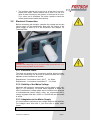
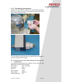
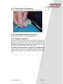
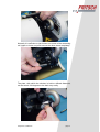
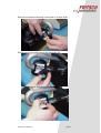
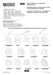
Remove and clean the windows. Insert them in reverse order. Do the same for the other side of the measuring cell. analysett 22 „COMPACT“ page 24 5.3 Measuring with the ”Dry Dispersing Unit“ In order to start measuring, the dust exhaust is first switched on through the dust exhaust control box. Then, the compressed air is switched on and followed by the vibrating feeder. In order to stop measuring, the steps are repeated in the reverse order. The feeder does not run during background measurement. The background measurement takes about 20 seconds as the measurement cycle is first cleaned each time. Immediately after the ”Background Measurement“ and before starting measurements, the feeder is switched on and controlled to predefined settings. After finishing with the measurements, the data is automatically downloaded and the particle size distribution is calculated. With the vibrating feeder you can set the ”Feed Rate“, which means the vibration amplitude and ”Quantity“, which means the distance between the funnel and the vibrating channel. Please make sure that the quantity is set as low as possible and the feed rate is as high as possible. This ensures the supply of a small sample layer to the nozzle and results in optimum conditions. The dry dispersing unit is a fully automatic system. Manual setting of the vibrating feeder with the keyboard does not store the settings for measurement. All manual settings are lost while measuring. If you want to pre-set the feeder, select the function ”Help“, ”Service“ and ”Manual Settings“ to save your specific presets for the measurement, e.g. ”Feed Rate“ and ”Quantity“. Normally, even this is not necessary. If you set the absorption between 2 and 5 percent, the vibrating feeder will supply as much sample as possible to meet this precondition. Firstly, the amplitude is increased and then after reaching a value of 99, the quantity too is increased in single steps. The settings for this measurement are stored in the result file and can be reloaded. In order to add sample material, set the feeder in the program (“Help“, ”Service“, ”Manual Settings“) to ”Feed Rate“ 0 and ”Quantity“ 0, and fill your sample material into the funnel. Set a small ”Quantity“ (depending on the adhesive power of your sample, normally to 0.3 to 1) and a medium ”Feed Rate“ of 50%. After pressing ”Start Measurement“, measurement is carried out with the pre-set values. analysett 22 „COMPACT“ page 25 6 Checking Communication After you have established the serial communication between the measuring unit and the computer, you should check the communication. For this, open the associated program "analysette 22 for windows" and select "Set system configuration" in the "Configuration" menu. In the "Set system configuration...“ window, select "Compact version wet". Subsequently, in the frame that appears at the top to the right-hand side, select the RS 232 interface of your computer to which you have connected the cable from the measuring unit. The "analysette 22 COMPACT" has an auto-alignment, which does not necessitate the manual adjustment of the laser beam. The beam intensity is NOT shown during a measurement, the index card is inactive. Caution: If the measuring cell is dirty, it can lead to higher intensities on the outer channels or the sensor channel are alternately displayed high and low. Then, auto-alignment possibly does not function any longer. It is absolutely essential to clean the glasses. The motors moving the sensor along the X and Y-axes may be destroyed. If, after approx. 3 minutes the beam adjustment has not been optimised, then the auto-alignment is interrupted with an error message. Do not restart auto-alignment under any circumstances, instead CALL FRITSCH SERVICE: The motors moving the sensor along the X and Y-axes may be destroyed. 7 Accessories 7.1 "analysette 22 WINDOWS" Program All functions of COMPACT version can be programmed and controlled with the "analysette 22 for WINDOWS“ program package. See the "analysette 22 for Windows" user's manual. 7.2 Small-Quantity Dispersing Unit See the "analysette 22 for Windows" user's manual. analysett 22 „COMPACT“ page 26 8 Maintenance Apart from regular cleaning, the analysette 22 COMPACT requires no maintenance. Before starting work in the machine, switch off the measuring unit and pull out the plug. 8.1 Selection of Liquids for Suspensions As, in the entire machine, the measuring liquid can come into contact with materials that are not chemically resistant, certain organic liquids and saturated inorganic salt solutions should not be selected. (The measuring liquid comes into contact with stainless high-grade steel, glass, Teflon and Viton (FPM and FKM) and Perbunan. The standard connecting hoses consist of PVC or polyethylene.) Only water is approved by Fritsch as suspension liquid for the dispersing unit. Before other measuring liquids are used, it is imperative that you first contact Fritsch. 9 Warranty The warranty card included with this machine, when it was delivered, must be completed and returned to the supplier for the warranty to become effective. The option of online registration is available. For further information, please refer to your warranty card or visit our Homepage http://www.fritsch.de Fritsch GmbH, Manufacturers of Laboratory Instruments, IdarOberstein and its "Application Technology Laboratory" or the respective area representatives will be glad to give advice and assistance. In the event of an enquiry, it is necessary to provide the details embossed on the identification plate. analysett 22 „COMPACT“ page 27 10 Troubleshooting Checklist 10.1 Checklist Malfunction Indicators not glowing Possible Cause Not connected to mains Master switch Mains fuse Elimination of Error Plug-in the mains plug Switch on master switch Replace mains fuse 10.2 Transferability of Measurement Results If the measurement of particles is used to ascertaining which of its assumed properties are real, the person conducting the measurement is not just an observer and the measurement equipment not just his tool; both are active participants. Therefore, in the determination of particle size distributions both participate in the achievement and type of result as well. While developing measurement equipment, the designer strives towards eliminating the influence of the operator for the most part. On the other hand, it is not possible to exclude the individual effect of the applied physical measurement method or its performance in the equipment. For example, if particle size distributions are determined using the sedimentation method (scanning photo sedimentograph "analysette 20") and the evaluation of a diffraction image, we must expect results that deviate at least slightly from one another. When particle sizes are measured using the analysis of a diffraction image, all dimensions of irregular particles are "seen" and accordingly taken into account in the result. Here, for example, the longitudinal extension of needle-shaped samples is also determined. The particle configuration has to be taken into account when comparing or transferring particle size distributions ascertained using different measurement methods. 10.3 Selection of Liquids for Suspensions Since the measuring liquid in the unit (dispersing and measuring unit) only comes into contact with materials which are chemically largely resistant, certain organic liquids or saturated inorganic salt solutions can be selected - without damaging the unit. (The measuring liquid comes into contact with high-quality stainless steel, glass, Teflon and Viton (FPM or FKM). The standard connecting tubes are made of Tygon.) A liquid suitable for measuring samples not compatible with water can be selected from the following listing: Basically we must warn against the use of explosive or inflammable liquids - they should not be recommended. The listing below is only to indicate the chemical compatibility of the unit vis-à-vis liquids. analysett 22 „COMPACT“ page 28 Monohydric, dihydric or trihydric alcohols (ethyl alcohol, isopropanol, glycol or glycerol, excl. methanol), mineral and organic oils (petroleum and soybean oil, nut oil, olive oil) It is imperative that you consult the factory before planning the use of other measuring liquids. The following may not be used: Ketones (acetone, propanone, butanone, cyclohexanone), ether, fluorochlorocarbons, amines, freone 21-32, methanol, aniline, benzol, chlorinated hydrocarbons acetic acids and its derivatives, undiluted acids and bases. Even samples that are present in oil (oils similar to machine oil, for example) do need not be measured in oil as well. Example: toner in machine oil The sample is first dispersed in ethylene glycol with a drop of a surface-active agent ("Pril") in the ultrasonic bath. A mixture in 1:1 proportion with water is then prepared and this is placed in the ultrasonic bath of the laser particle sizer "analysette 22". Example: crude cocoa mass The crude cocoa mass is generally measured in acetone or benzene (familiar from the straining operation). The measurement in the "analysette 22" can also be performed in peanut oil, for example. Since peanut oil is safe to use with foodstuffs, the "waste oil" can be used as lubricant on the rollers, thus solving the problem of disposal. Example: slightly magnetic materials In general, particle size distributions of magnetic materials in suspension are not measured because of the reciprocal attraction between the individual particles. On the one hand, the high sensitivity of the "analysette 22" makes it possible to suspend materials in very low concentrations, although at relatively large distances between the individual particles, and, on the other hand, the high performance of the centrifugal pump permits this to be done with high viscosity liquids. In the example presented here, strontium ferrite was measured in a suspension of glycerine and water at a ratio of 1:1. If relatively large particles or particles of relatively high density are to be measured, the percentage of glycerine can be simply raised to a ratio of 7:3. In general, liquids with a viscosity of 30 cPoice can still be circulated by the pumping system of the dispersing unit. analysett 22 „COMPACT“ page 29 10.4 Dispersing Samples with Poor Wettability Despite their water-repellent properties, hydrophobic samples can be dispersed if made into a paste beforehand with a liquid surface-active agent ("Pril") and then dispersed in water while being constantly stirred. In addition, agglomerates are dispersed more easily and more quickly in an external ultrasonic bath, since the total sample there is subjected to the ultrasonic. In the circuit of the dispersing unit, only the portion of the sample in the bath is in the area of the ultrasonic. In the case of soil samples, for example, a 0.1 – 0.5% sodium pyrophosphate solution is recommended to promote dispersion. The sample thus prepared can be measured in pure water. 10.5 Measuring of Samples with Low Solubility Samples exhibiting low solubility in liquid can also be measured in the laser particle sizer "analysette 22". Here, it is advisable to prepare a saturated measuring liquid. In such a solution the particle size cannot change by dissolving. Hence the measurement results cannot be corrupted. (However the saturated solution has to be filtered prior to use.) Where very expensive products are involved, it may also be beneficial to identify a replacement substance, which assumes the function of "saturating" the measuring liquid. analysett 22 „COMPACT“ page 30