1
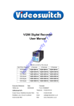
VDC Digital Recorder
User Manual
Products covered by this manual
4
9
(with Ethernet)
(with Ethernet)
VDC-9G80
VDC-4G80E
VDC-9G80E
VDC-4G160
VDC-9G160
VDC-4G160E
VDC-9G160E
VDC-4G250
VDC-9G250
VDC-4G250E
VDC-9G250E
Cameras / Hard Drive
Capacity
4
9
80 Gbytes
VDC-4G80
160 Gbytes
250 Gbytes
Document Reference
Date
Firmware
Vdc601a.doc
05/01/2004
VDC001A9
Videoswitch
Units 15 & 16 Redfields Industrial Park
Telephone
01252-851510
Redfields Lane
Fax
01252-851296
Church Crookham
Email
[email protected]
Hants GU52 0RD
Web
www.videoswitch.co.uk
VDC Digital Recorder
Vdc601a.doc
VDC Digital Recorder
Contents:
Start Here ............................................................................................................................................ 1
1
1.1
Connecting Up ........................................................................................................................................................................2
1.2
Setting Date and Time ............................................................................................................................................................3
1.3
Recording ...............................................................................................................................................................................3
1.4
Routine Checks ......................................................................................................................................................................3
1.5
Care of the Hard Drive............................................................................................................................................................3
1.6
Critical Alerts...........................................................................................................................................................................4
1.7
Power On Reset .....................................................................................................................................................................4
2
Viewing Live Images .......................................................................................................................... 5
2.1
Viewing Full Screen Images ...................................................................................................................................................5
2.2
Quad Display ..........................................................................................................................................................................5
2.3
9-way Multi-Screen (VDC-9 only) ...........................................................................................................................................5
2.4
Auto-Sequencing ....................................................................................................................................................................6
2.5
Inhibiting Alarms .....................................................................................................................................................................6
3
4
5
6
7
8
9
Time/Date Search ............................................................................................................................... 7
Playback Controls .............................................................................................................................. 8
Sweep Mode........................................................................................................................................ 9
Event List........................................................................................................................................... 10
Writing Incidents to CD.................................................................................................................... 11
Replaying a CD ................................................................................................................................. 12
Information Screens......................................................................................................................... 13
9.1
Drive Information ..................................................................................................................................................................13
9.1.1
9.2
Re-Scan Drives.................................................................................................................................................................13
Image Information.................................................................................................................................................................14
9.2.1
9.2.2
Live ...................................................................................................................................................................................14
Play...................................................................................................................................................................................14
9.3
System Information...............................................................................................................................................................15
10
11
Using the Menu................................................................................................................................. 16
Menu Reference................................................................................................................................ 18
11.1
Date/Time .............................................................................................................................................................................18
11.2
Record ..................................................................................................................................................................................18
11.2.1
Days..................................................................................................................................................................................18
11.2.2
Cameras ...........................................................................................................................................................................19
11.2.3
11.3
Quality...............................................................................................................................................................................19
Display ..................................................................................................................................................................................19
11.3.1
Camera Titles ...................................................................................................................................................................19
11.3.2
Auto Sequence Dwell .......................................................................................................................................................19
11.3.3
Record Brightness ............................................................................................................................................................19
11.3.4
11.4
Record Colour Boost ........................................................................................................................................................20
Alarms...................................................................................................................................................................................20
11.4.1
Activity Detection ..............................................................................................................................................................20
11.4.2
Alarm Hold Time ...............................................................................................................................................................20
11.4.3
Video Loss Alert................................................................................................................................................................20
11.4.4
Hard Drive Alert ................................................................................................................................................................20
11.4.5
11.5
Clear Event List ................................................................................................................................................................20
Network.................................................................................................................................................................................21
11.5.1
Dial-Up Type.....................................................................................................................................................................21
11.5.2
IP Address ........................................................................................................................................................................21
11.5.3
Sub-Net Mask ...................................................................................................................................................................21
11.5.4
Gateway............................................................................................................................................................................21
11.5.5
11.6
Port ...................................................................................................................................................................................21
Config ...................................................................................................................................................................................21
11.6.1
Upgrade from CD..............................................................................................................................................................21
11.6.2
Restore Factory Config.....................................................................................................................................................21
11.6.3
Erase Hard Drive ..............................................................................................................................................................21
11.6.4
Password ..........................................................................................................................................................................22
Vdc601a.doc
VDC Digital Recorder
11.6.5
12
13
System Address ............................................................................................................................................................... 22
Changing the Hard Drive.................................................................................................................. 23
PSTN and ISDN Dial-Up.................................................................................................................... 24
13.1
Fitting the VDC/PSTN or VDC/ISDN Option ........................................................................................................................ 24
13.2
Using the VDC/PSTN or VDC/ISDN Option ......................................................................................................................... 24
14
Specifications ................................................................................................................................... 25
14.1
14.1.1
14.1.2
Connector Pin-Outs.............................................................................................................................................................. 25
Alarms .............................................................................................................................................................................. 25
Keyboard .......................................................................................................................................................................... 25
14.2
Image Capture and Storage ................................................................................................................................................. 26
14.3
Physical and Environmental ................................................................................................................................................. 26
14.3.1
Power Requirements........................................................................................................................................................ 26
14.3.2
Dimensions and Weight ................................................................................................................................................... 26
14.3.3
Temperature and Humidity............................................................................................................................................... 26
14.3.4
Ventilation ........................................................................................................................................................................ 26
14.3.5
Safety ............................................................................................................................................................................... 26
Vdc601a.doc
VDC Digital Recorder
1
Start Here
REMOVABLE HARD DRIVE
HARD DRIVE LOCK
DISC POWER (RED)
DISC ACTIVITY (GREEN)
FAN 1 OK (GREEN)
CD WRITER
FAN2 OK (GREEN)
OPEN CD DRAWER
SYSTEM POWER (RED)
The VDC Digital Recorder provides a one-box solution for multiplexing, digital recording of video images
from up to 9 cameras. It also includes a CD writer for backup and options for remote viewing via a dial-up or
Ethernet connection.
•
All you need for a digital recording system is the VDC recorder, up to 9 cameras and a display
monitor. This set-up will permit the video images from all the cameras to be recorded onto hard disc
for a period of typically 31 days. Beyond that time, the oldest images will be over-recorded by new
images. The number of days is selected the user and the VDC automatically calculates the update
rate to achieve this target.
•
Any images available on the hard disc can be played back without interrupting the recording
process. The active SEARCH facility allows images to be found by time and date.
•
The SWEEP mode allows the contents of the hard drives to be rapidly scanned for the easy location
of particular areas of interest even when the date and time is not known.
•
An EVENT list records alarms generated by the built-in activity detection and by external alarms
(e.g. PIR detectors). Events may be instantly recalled and replayed.
•
For permanently archiving images, a CD writer is included as standard in all VDC recorders. An
INCIDENT list is used to mark any sections of video that you wish to archive onto CD. A CD-R disc
provides a permanent record suitable for police use.
•
Incidents stored onto CD may be played back in any VDC, a VDM, or on a PC (no software
installation required)
•
The CD drive is also used to install firmware updates to the system. These will be made available on
CD and on the Internet if new features become available.
•
The removable hard drive provides the user with the ability to upgrade the drive capacity at any
time. Additionally, it also means minimal “down time” if the drive fails in service; a replacement drive
can be sourced and plugged in without the need for disconnecting the system.
Vdc601a.doc
1
VDC Digital Recorder
1.1
Connecting Up
PSTN or ISDN (OPTION)
ALARMS
ETHERNET (OPTION)
CAMERA INPUTS
REMOTE KEYBOARD
MAINS POWER INPUT
MAINS VOLTAGE SELECT
MONITOR OUTPUT
•
•
•
•
•
•
•
•
•
Connect the video input of the Monitor to the monitor output of the VDC using a BNC cable
Make sure that the monitor termination is switched on (i.e. to 75 Ohms)
Connect the first camera to Camera Input 1 on the VDC using a BNC cable
Connect the next camera to Camera Input 2 on the VDC using a BNC cable
Connect the next camera to Camera Input 3 on the VDC using a BNC cable
Connect the next camera to Camera Input 4 on the VDC using a BNC cable
Make sure that the voltage select switch is set to suit the mains supply voltage prior to applying
power otherwise damage may occur. The setting required in UK and Europe is 230Vac.
Connect the mains power using the IEC cable supplied using an IEC to 13A plug cable (provided)
When power is applied, the system will perform a self-test prior to displaying live images.
Vdc601a.doc
2
VDC Digital Recorder
1.2
Setting Date and Time
For proper operation of the VDC Digital Recorder is essential that the date and time are set correctly.
If the system clock has an invalid date or time when the VDC is powered up (or at any time during
operation), the date and time setting window will be automatically displayed
If this occurs, use the keys 0, 1, 2, 3, 4, 5, 6, 7, 8, 9 and 0 to enter the date and time.
The format for the date and time is DD/MM/YY HH:MM:SS where:
•
DD is the day of the month (00 to 31),
•
MM is the month (01 to 12),
•
YY is the year (e.g. 04 for the year 2004),
•
HH is the hour in 24-hour format (00 to 23),
•
MM is the number of minutes past the hour (00 to 59) and
•
SS is the number of seconds past the minute (00 to 59).
If you need to adjust the time and date at any time, enter the menu by pressing the SETUP key (see section
11). The time is automatically adjusted forwards or backwards by an hour at the appropriate dates to take
account of British Summertime so no user action is required.
1.3
Recording
The VDC Digital Recorder should now be fully operational and recording images from all cameras. The
default image retention period is 31 days. Refer to the following sections of this manual for details on
controlling and configuring the system.
If the system is not recording, the message STOP will be displayed on the screen. This should only happen
if no hard drive is fitted, or if you have de-selected all cameras in the record menu (Section 11.2.2).
1.4
Routine Checks
Although the system is intended for continuous un-attended operation, it is recommended that the user
regularly check that images from all cameras replay correctly. Any potential problems with the cameras
or recording system will then be detected as soon a possible, rather than continuing un-noticed until a critical
incident needs to be recalled from the system.
Similarly, when a CD has been created you should check that it plays back correctly, before the
images are over-recorded on the VDC. The CD may be checked by either by playing it on a VDC or on a
PC.
1.5
Care of the Hard Drive
The hard drive is a delicate mechanical item that should be handled with care. Before moving a VDC that
has bee powered up, remove power and wait for 30 seconds for the drive to stop spinning. This is a
precaution to avoid possible damage to the hard drive.
Vdc601a.doc
3
VDC Digital Recorder
1.6
Critical Alerts
The VDC constantly monitors the hard drive, camera inputs and system so that detected fault conditions will
be reported to the user as soon as possible by means of a “critical alert” message on the screen. Alerts are
also added to the event list.
Press the EVENTS key to view the event list (pressing the DEFAULT key automatically scrolls to the most
recent events.
Viewing the list will cancel the alert message. However if the condition persists, the message will re-appear.
• FailTest
This alert indicates that the system self-test has failed.
o
Press ALT and SETUP to call up the System Information screen. The positions
of any solid blocks displayed on the “Self Test” row indicate various fault
conditions.
o
Try power cycling the VDC to see if the problem is fixed, or failing this.
o
Try a power-on reset (See section 1.7).
o
If the problem persists, contact your supplier.
• VidLoss
This alert means that video has been lost on one or more of the camera inputs.
o
Make sure that the video loss setting in the menu (see section 11.4.3)
corresponds with cameras actually fitted.
o
Check connections to all cameras.
o
Check that each camera can be viewed in live, full screen mode.
o
Swap a camera input that is working with the one that is not. Does the problem
move with the camera (i.e. faulty camera or cable) or stay with the input (possible
faulty VDC)
o
If a camera is suspected as being faulty, connect it directly to a monitor to test it.
• HD1 Fail
This alert indicates that the hard drive is not working.
o
Check that the drive drawer is correctly fitted
o
Check the lock in the drive drawer is turned full counter-clockwise
o
Check the DISC ACTIVITY LED is flickering (see diagram in section 1)
o
Check that the green FAN1 OK and FAN2 OK LEDs are lit.
o
Check that the red DISC POWER led it lit.
• HD1 SMART
This alert indicates that the hard drive may stop working soon
o
1.7
The SMART monitoring detects imminent failure of a hard drive, so if this warning
occurs, the drive should be changed at the earliest opportunity.
Power On Reset
If you wish to perform a power-on-reset to restore all settings to their factory defaults, press the ALT key
while you apply power, and keep pressing it until the VDC has powered up and displays FACTORY
RESET. Note that this process will reset all user settings, including titles and password.
Vdc601a.doc
4
VDC Digital Recorder
2
Viewing Live Images
Press this key to enter LIVE mode:
2.1
Viewing Full Screen Images
Select full screen views of different cameras by pressing the NUMERIC keys:
2.2
Quad Display
Select quad display by pressing the QUAD key (live display only):
2.3
9-way Multi-Screen (VDC-9 only)
Select x9 Multi-Screen display by pressing the MULTISCREEN key (live display only):
Vdc601a.doc
5
VDC Digital Recorder
2.4
Auto-Sequencing
Select auto-sequencing on the monitor by pressing the ALT and the SEQ keys at the same time. Auto
sequencing is cancelled by pressing these two keys again, or by pressing any camera select (NUMERIC)
key.
The message SEQ is displayed at the top of the screen when sequencing is enabled. You may specify the
dwell time via the menu.
2.5
Inhibiting Alarms
If alarms have been enabled (see section 11.4.1), they can
be temporarily inhibited by pressing the ALT and NO keys
at the same time.
Vdc601a.doc
The letters INH will appear on the
screen when alarm are inhibited
6
VDC Digital Recorder
3
Time/Date Search
If there is a valid CD in the CD drive, images will replay from the CD. Otherwise, images will replay
from the built-in hard drive.
This is the main search mode that is used to recall recorded
images. Press the SEARCH key to enter the search mode.
Use the NUMERIC keys to enter
any date and time for which there is
still video available.
Sometimes it is useful to press the
DEFAULT key when in search mode,
to call up the latest available recorded
images
The format for the date and time is DD/MM/YY HH:MM:SS
where:
•
DD is the day of the month (00 to 31),
•
MM is the month (01 to 12),
•
YY is the year (e.g. 04 for the year 2004),
•
HH is the hour in 24-hour format (00 to 23),
•
MM is the number of minutes past the hour (00 to 59)
and
•
SS is the number of seconds past the minute (00 to 59).
Scroll through dates and times using the ARROW keys:
Note that as any digit of the date and time
is changed, the corresponding image is
immediately found on the hard drive and
displayed.
This is the “active search” facility.
Vdc601a.doc
7
VDC Digital Recorder
4
Playback Controls
Having found what you want, you can use the PLAYBACK
keys to move forwards and backwards through the recorded
video images.
Press the forward or reverse play
keys repeatedly to increase the
replay speed.
The function of each key is:
Step backwards one image
Step forwards one image
Play backwards (press again to increase speed)
Play forwards (press again to increase speed)
Pause at currently displayed image
View different cameras by pressing the NUMERIC keys:
Vdc601a.doc
8
VDC Digital Recorder
5
Sweep Mode
An alternative to the date/time search, is the sweep facility. Press these keys at the same time to enter the
sweep mode:
To step between start, middle and end, press this key:
Now use these keys to scan through the whole range of
recorded images:
To step in finer time increments, press
the NO key to access the fine mode.
Note that the slider changes from a solid
block to a diamond.
Press again to cancel.
When you have found what you want, use the normal play functions:
Vdc601a.doc
9
VDC Digital Recorder
6
Event List
If activity detection has been enabled (see section 11.4.1) or if alarm contacts are being used, there may be
events in the event list. Press the EVENT key to view the event list.
Entering the EVENT screen clears any
critical alert conditions. If a critical alert
problem still exists, new alert events will be
created.
Use the up/down keys to scroll through events and the
left/right keys to select different pages of events.
Up to 480 events can be recorded before
older ones are over-written.
As events are highlighted, the corresponding
image will be immediately recalled and
displayed.
Vdc601a.doc
10
VDC Digital Recorder
7
Writing Incidents to CD
Incidents are used to mark sections of video for subsequent writing
to CD. Find the section of video you wish to backup to CD, and then
call up the incident screen by pressing the INCIDENT key.
Mark an incident by pressing the DEFAULT key.
If you wish to change the start or end
times of the incident, use the left/right
keys:
Up to 4 incidents may be set at
once. Use the UP and DOWN
arrow keys to select a spare
incident, or re-use an incident
that you have already backed
up to CD.
This is the quickest way to set an incident. 400
images either side of the image last played back will
be selected. The incident will use about 16Mbytes.
The time span will depend on the number of
cameras and the image retention period. Once set,
the incident can be adjust in size if required.
Incidents may also be set by finding the first image that you
want, entering the incident mode and pressing ALT and
START to set the incident start.
The last image required should then be recalled, and the
incident screen entered again. This time press ALT and
END to mark the end of the incident.
Press the NO key if you have made it
too big, and wish to undo the last
increase:
The individual size of incidents is shown on the right hand
side of the screen, and the total underneath.
Each incident has a Y or N associated with it on the screen.
The Y indicates that the incident will be written to CD, whilst
the N indicates that it will not be written.
Press the “YES” key to toggle the option for each incident.
The total size must not exceed the available size of the CD
(around 650 to 750 Mbytes).
Start writing to CD by pressing this key:
Vdc601a.doc
Note that you can only write incidents to a blank CD. When
important incidents have been written to a CD, always
check that the CD plays back correctly, either by playing
it on the VDC or on a PC.
11
VDC Digital Recorder
8
Replaying a CD
Press the “Open CD drawer” button on the CD drive, and place the CD on the drawer. Press the “Open CD
drawer” button again to close it.
Replaying a CD is similar to replaying from hard
Call up the incident screen by pressing this key,
disc, although you will sometimes have to wait a
and wait until CD appears on the screen,
few seconds while the CD spins up to speed. The
indicating that the displayed incidents are from
letters CD are display on the top of the screen
the CD, not the hard disc.
when replaying from a CD.
Select the incident that you wish to replay using these keys:
Press this key to play forwards from the start of the selected incident:
Alternatively, press this key to play backwards from the end of the selected incident:
Vdc601a.doc
12
VDC Digital Recorder
9
Information Screens
A number of information screen are available to tell you about the VDC and to confirm that it is operating in
the way that you intended.
9.1
Drive Information
To see what drives are fitted and whether a CD is in the CD drive press these keys at the same time:
This screen displays this information:
•
CD drive type
Confirms that the CD drive is fitted and functioning
•
Hard drive type
Confirms that the hard drive is fitted and functioning
•
Drive Capacity
The larger the capacity, the faster the image update rate will be for a given
number of days image retention.
•
SMART monitoring
Tells you if the hard drive is likely to fail in the near future
•
Earliest Date/Time
Images are still available back to this time
•
Latest Date/Time
This is the time of the most recently recorded image
9.1.1
Re-Scan Drives
If the hard drive has been replaced, or if the CD or hard drives are not operating correctly, or if the earliest
and latest dates are thought to be in error, the drives may be re-scanned by pressing this key:
Vdc601a.doc
13
VDC Digital Recorder
9.2
Image Information
To enter the image information screen, press these keys at the same time:
This screen displays different information in LIVE and PLAY modes:
9.2.1
Live
In LIVE mode, the Image Information screen displays the following:
•
Current overall record rate
•
Image retention period in days
•
Record mode (normal or alarm)
•
Connected cameras
•
Average image size
•
Date of available images
9.2.2
Play
In PLAY mode, the Image Information screen displays the
following information about the current image:
•
Date/Time
•
Time zone (summertime, wintertime)
•
Camera number
•
Image size
•
Image number (all images are numbered)
•
Serial number of VDC on which image was recorded
•
Revision of firmware at the time the image was recorded
•
Position of the index and image on the hard drive
•
Digital signature authentication
Vdc601a.doc
Each image includes a digital
signature, which enables the
system to verify its integrity. The
signature is checked on replay, and
this status screen will report either
that it has been authenticated or
rejected.
The signature is carried with the
image if it is copied to CD and
subsequently transferred to a
computer. If any images have been
modified,
the
authentication
process will fail.
14
VDC Digital Recorder
9.3
System Information
To display the system information, press these keys at the same time:
The information displayed includes:
•
Model
•
Serial Number
•
Firmware/Logic Revision
•
Firmware Checksum
•
PCB revision
•
Self test results (and error codes if applicable)
•
Where Ethernet option is installed
•
Whether PSTN or ISDN option is installed
•
Current list of inputs with video present
•
Current status of alarm inputs (subject to alarm timer)
•
Current status of activity detection (subject to activity timer)
Vdc601a.doc
15
VDC Digital Recorder
10
Using the Menu
To enter (and exit from) the menu, press the SETUP key:
The main menu has the following options:
•
Date/Time
Select this option to set the VDC to current date and time.
•
Record
This sub-menu allows you to set the number of days to retain images, and also the
image quality and which cameras are to be recorded all the time.
•
Display
This sub-menu allows you to set camera titles and other thing related to display.
•
Alarms
Activity and relay options are set in this sub-menu. The event log may also be
cleared.
•
Network
Dial-up and Ethernet setting are made within this sub-menu.
•
Config
Restore factory configuration and set a password in this sub-menu.
These menus are described in more detail in section 11.
The ARROW keys are used to move through the menu and to alter settings within the menu:
In many instances, if you are uncertain about a menu setting, the default option can be selected using the
DEFAULT key:
In parts of the menu you may need to initiate an action by pressing the YES key:
Vdc601a.doc
16
VDC Digital Recorder
In parts of the menu you may need to enter numbers using the NUMERIC keys:
You can use the NO key to go back a level in the menus:
To exit from the menu, press the SETUP key:
Vdc601a.doc
17
VDC Digital Recorder
11
Menu Reference
11.1 Date/Time
Use the arrow and numeric keys to
set the date and time. Summertime is
automatically catered for, so no
adjustment will be needed other than
regularly checking that the time is
accurate (like all clocks, some drift
will occur).
The format for the date and time is DD/MM/YY HH:MM:SS
where:
•
DD is the day of the month (00 to 31),
•
MM is the month (01 to 12),
•
YY is the year (e.g. 04 for the year 2004),
•
HH is the hour in 24-hour format (00 to 23),
•
MM is the number of minutes past the hour (00 to 59)
and
•
SS is the number of seconds past the minute (00 to 59).
11.2 Record
11.2.1
Days
Use the NUMERIC keys to enter how
may days you wish images to be
retained for.
The fewer the number of days, the faster the update rate will
be. For images of typical size (around 17K bytes), this table
gives an indication of expected update rates in images per
second:
Image Retention/ Drive Size
80G
160G
250G
7 Days
7.8
12.5
12.5
14 Days
3.9
7.8
12.2
31 Days
1.8
3.5
5.5
For comparison, the update rate on a time-lapse VCR set
for 24 hour mode is about 5.5 images/second – but the tape
only lasts 27 hours.
Note that IMAGE INFORMATION screen displays an
image retention value that may vary slightly as image
conditions alter. If alarms are used, you may wish to set a
greater number of days than is required to compensate for
the fact that alarm recording uses the disc more quickly.
Vdc601a.doc
18
VDC Digital Recorder
11.2.2
Cameras
This option specifies which cameras will be recorded
when there are no alarms active. The solid block
indicates that a camera will be recorded; a dash
indicates that it will not be recorded.
Only inputs that have cameras will be recorded, so if
you do not have cameras on all the inputs, all blocks
can still be left set.
If you want to record one or more cameras only
when there is activity or an alarm, turn those
cameras off here.
Using the large hard drive sizes available in the
VDC, it is often best to record all cameras all
the time.
Use the ARROW keys to alter the cameras
individually.
Press the DEFAULT key to turn all block on or off.
The normal setting is all blocks on.
11.2.3
Quality
The record quality (image size) of each camera can
be adjusted.
Use the ARROW keys to alter the settings.
Small images sizes mean there is space for more
images on the hard disc, so the update rate will
increase. However, the image quality will be less
so there is a trade-off.
The image size is displayed. Note that it may take
several seconds to stabilise to a new value.
The exact image size depends on the complexity
of the image, so simple scenes (e.g. dark or empty
rooms) do not waste disc space.
11.3 Display
11.3.1
Camera Titles
Each camera may be given a title, or the default title may be used (Camera1, Camera2 etc).
You can use the NUMERIC keys for numbers and the UP and DOWN arrow keys to get letters and other
characters. Press the NO key to go back to the previous menu level.
11.3.2
Auto Sequence Dwell
When auto-sequencing cameras, the dwell time is specified by this option.
11.3.3
Record Brightness
The brightness of the images being recorded can be adjusted to compensate for cable losses. Adjust the
brightness as required for each camera.
•
If the displayed image (which is digitised) is too dim or is tearing, increase the brightness setting.
•
If an image is too bright, decrease the brightness setting.
Vdc601a.doc
19
VDC Digital Recorder
11.3.4
Record Colour Boost
The colour content of the images being recorded can be adjusted here to compensate for cable losses.
Adjust so that the displayed image if necessary so that the colour content is not too weak or too strong.
11.4 Alarms
11.4.1
Activity Detection
Activity detection may be enabled on each camera. Select the required camera using the UP and DOWN
keys, then press the RIGHT key to enter the activity screen for that camera.
When the top row of text is highlighted, the sensitivity is set using the NUMERIC keys 1,2,3,4,5.
When the top row text is highlighted, the number of active pixels required for detection is set using
NUMERIC keys 6,7,8,9,0.
When any of the other rows is highlighted the NUMERIC keys are used to individually enable (shown by a
“+” symbol) or disable activity pixels (blank).
To enable or disable all activity pixels, press the DEFAULT key.
Activity pixels that are enabled will be displayed as a solid block when activity is detected (this is affected by
sensitivity).
When the number of pixels required for detection are simultaneously activity, the word ACT appears at the
top of the screen. This is when the relay activates.
11.4.2
Alarm Hold Time
When an activity or alarm contact activates, the relay is energised for the period specified by this setting.
The record rate increases to 12.5 images per second while the relay is energised.
11.4.3
Video Loss Alert
This option specifies which inputs are to be monitor for video loss. Only set blocks ON for those inputs that
have video, or else a critical alert message will appear. The easiest way to select the correct blocks is to
press the DEFAULT key (all required cameras must be connected when this is done).
11.4.4
Hard Drive Alert
This option specifies whether a hard disc problem causes a critical alert. This option should normally be set
to YES.
11.4.5
Clear Event List
Select this option and press the YES key to clear the event list. One event item will be put in the list to
indicate when it was cleared.
Vdc601a.doc
20
VDC Digital Recorder
11.5 Network
11.5.1
Dial-Up Type
The type of dial-up option module fitted should be specified here (PSTN or ISDN). If no module is fitted, this
option is ignored.
11.5.2
IP Address
If the VDC has an Ethernet option fitted, this setting specifies the IP Address. Contact the network
administrator to obtain a suitable setting. Press the DEFAULT key to use the factory default setting. If the
Ethernet module is not installed, this setting is ignored.
11.5.3
Sub-Net Mask
If the VDC has an Ethernet option fitted, this setting specifies the sub-net mask. Press the DEFAULT key to
use the factory default setting. If the Ethernet module is not installed, this setting is ignored.
11.5.4
Gateway
If the VDC has an Ethernet option fitted, this setting specifies the Gateway. Contact the network
administrator to obtain a suitable setting. Press the DEFAULT key to use the factory default setting. If the
Ethernet module is not installed, this setting is ignored.
11.5.5
Port
If the VDC has an Ethernet option fitted, this setting specifies the Port. Press the DEFAULT key to use the
factory default setting. If the Ethernet module is not installed, this setting is ignored.
11.6 Config
11.6.1
Upgrade from CD
If you wish to upgrade the VDC from an upgrade CD, put the CD in the CD drive, wait for the upgrade
revision to be displayed, and press the YES key.
Once the upgrade process starts, wait until the system restarts before touching any keys. Do not remove
power until this process has completed otherwise the system could be left inoperative.
11.6.2
Restore Factory Config
Press the YES key to restore the configuration to the factory defaults.
11.6.3
Erase Hard Drive
Press the YES key to erase the hard drive.
Vdc601a.doc
21
VDC Digital Recorder
11.6.4
Password
If you wish to set a password, enter a four digit number here. This password will be needed every time the
menu is entered, and if remote access is used. It is important that you remember this number.
Note that if this password is forgotten, a power on reset will be necessary to regain access. This will return
all menu settings to their factory defaults.
11.6.5
System Address
This address need only be changed if more than one VDC is to be controlled from one remote keyboard.
In this case, give each VDC a unique address. For example “001”, “002”, “003” etc.
Vdc601a.doc
22
VDC Digital Recorder
12
Changing the Hard Drive
The VDC Digital Recorders is supplied with a removable hard drive.
Hard drives are sensitive mechanical devices that may be damaged by shock or vibration. Always handle
with care and when transporting drives, ensure they are well cushioned with suitable padding to protect
them from shock and vibration.
Remove power from the VDC before removing the hard drive. Wait for 30 seconds for the drive to stop
spinning before moving the VDC or removing the hard drive.
The hard drive drawers require a special key to unlock them. Insert the key, and turn it clockwise to unlock
the drive.
To put a hard drive back into the VDC, make sure that the lock in the drive drawer is in the unlocked
position. Carefully slide the drawer in as far as it can go with the handle in the up position. Carefully push the
handle down such that the drawer is pulled into the drive bay. When it is properly located, lock the drawer by
turning the key counter-clockwise.
After changing a drive, re-apply power to the VDC.
Vdc601a.doc
23
VDC Digital Recorder
13
Remote Dial-Up
4
4
5
3
6
1 2
1
13.1 Fitting the VDC/PSTN or VDC/ISDN Option
1. Remove the mains power to the VDC digital recorder
2. Remove the options module blanking on the VDC digital recorder (4 screws)
3. Plug one end of the supplied ribbon cable into…
4. … the 10-pin header inside the VDC (make sure all the pins line up on both rows)
5. Plug the other end of the ribbon into 10-pin header on the VDC/PSTN or VDC/ISDN module (make
sure all the pins line up on both rows). Note that the module must be orientated with the metal
bracket at the bottom, PCB on top.
6. Carefully fit the modem module into the VDC digital recorder and replace the 4 screws (M2.5) to
securely fix it to the rear panel.
13.2 Using the VDC/PSTN or VDC/ISDN Option
1. Connect to a telephone (PSTN or ISDN) line using the cable provided.
2. Upgrade the firmware in the VDC digital recorder to the latest version (VDC001A5 or later). Make
sure that PSTN or ISDN is selected in the menu: [Setup][Remote Access][Dial-Up Type].
3. Install “VDM-Connect” (Issue VDM017i or later) onto the PC that is to be used for remote access.
4. Click on SITE on the VDM-Connect and add the phone number to the site list.
5. Click on “Connect”. Images should be displayed on the PC after connection with the VDC has been
established.
Vdc601a.doc
24
VDC Digital Recorder
14
Specifications
14.1 Connector Pin-Outs
14.1.1
Alarms
Physical:
RJ45 (upper connector)
Electrical:
Alarm Inputs:
Contact closure
Alarm Output:
N/O Relay Contacts, 24V 500mA max
Pin Number
Signal
In/Out
1
RS485+ (A) Loop Out
Out
2
RS485- (B) Loop Out
Out
3
Alarm 4
In
4
Alarm 3
In
5
Alarm/Relay Common (0V)
Out
6
Alarm 2
In
7
Alarm 1
In
8
Relay N/O
Out
14.1.2
PIN1
Keyboard
Physical:
RJ45 (lower connector)
Electrical:
RS485
Pin Number
Signal
In/Out
1
RS485+ (A)
In
2
RS485- (B)
In
3
Not used
N/a
4
+12V for Keyboard
Out
5
0V for keyboard
Out
6
Not used
N/a
7
Twisted-Pair Video+
Out
8
Twisted-Pair Video-
Out
Vdc601a.doc
PIN8
PIN1 PIN8
25
VDC Digital Recorder
14.2 Image Capture and Storage
Displayed Image Format
720 x 576 Pixels, 16 Million colours
Compressed Image Format
720 x 288 Pixels, 16 Million colours
Sample rate
13.5Mhz
Image Compression System
Wavelet
14.3 Physical and Environmental
14.3.1
Power Requirements
Voltage
Power
14.3.2
115Vac or 240Vac 50/60 Hz
50W maximum
Dimensions and Weight
Unit
Width
Depth
Height (including feet)
Weight
160mm
310mm
200mm
Kg
Packaged
14.3.3
Kg
Temperature and Humidity
Temperature
Humidity
14.3.4
Operating
Storage
10 to 30 º C
5 to 95% non-condensing
-20 to 60 º C
5 to 95% non-condensing
Ventilation
The VDC Digital Recorder has ventilation holes in the base, front and rear. Using internal fans, the unit
creates a continuous flow of air through the unit to control the temperature of the disc drives and other
internal components.
The ventilation holes must not be obstructed otherwise the lifetime and reliability of the system may be
affected.
14.3.5
Safety
For warranty and safety reasons, the cover of this equipment must not be removed. There are no user
serviceable parts inside.
Vdc601a.doc
26
Notes