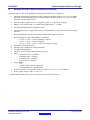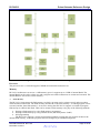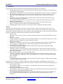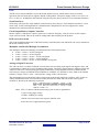
1
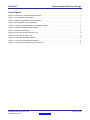
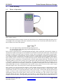
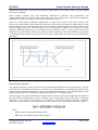
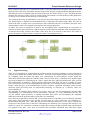
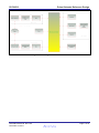
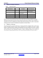
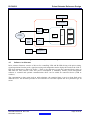
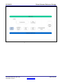
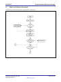
APPLICATION NOTE RL78/G13 Pulse Oximeter Reference Design R01AN0716EU0100 Rev.1.00 November 15, 2011 Introduction The primary function of red blood cells is to transport oxygen from lungs to tissues. A substance called Hemoglobin carries out this function. When blood is circulated in to lungs, oxygen is attached to hemoglobin, forming oxygenated hemoglobin. When the blood is in capillaries, oxygen is released from oxyhemoglobin and delivered to the cells. The deoxyhemoglobin returns back to lungs to get saturated with oxygen once again. The percentage of oxygen saturation of hemoglobin in arterial blood (SaO2) is determined by the Pulse oximeter. It is a medical instrument which optically measures oxygen saturation (SaO2) in patient’s blood. In modern medical practice, the blood oxygen level is considered one of the important vital signs of the body along with the more traditional ones, such as blood pressure, heart rate, body temperature, and breathing rate. Pulse oximeters provide early information on problems in the respiratory and circulatory systems. They are widely used in intensive care, operating rooms, emergency care, birth and delivery, neonatal and pediatric care sleep studies, and in veterinary care [6]. Pulse oximetry combines the principles of photoplethysmography and spectrophotometry to measure noninvasively the oxygen saturation of arterial blood. This is an important tool to assess the status of patient oxygenation. This is the one of the most advanced patient monitoring technology. It provides safe, continuous and cost effective monitoring of blood oxygenation noninvasively at the patient bedside. Pulse oximeters are widely used in clinical practice. They are used extensively in the intensive-care units to monitor oxygen saturation, and to detect and prevent hypoxemia. They are used to monitor patients during procedures like bronchoscopy, endoscopy, cardiac catheterization, exercise testing and sleep studies. They are also commonly used during labor and delivery for both mother and infant. A pulse oximeter is connected to the patient using a finger probe to detect the actual level of oxygen in the patient's blood stream. Contents 1. Pulse Oximetry .................................................................................................................................. 3 2. Pulse Oximeter Device Requirements .............................................................................................. 8 3. Renesas RL78/G13 Device Architecture Overview ........................................................................ 10 4. Reference Design Architecture ....................................................................................................... 14 5. High Level Software Flowcharts ...................................................................................................... 18 Appendix A – References ........................................................................................................................ 22 R01AN0716EU0100 Rev.1.00 November 15, 2011 Page 1 of 23 RL78/G13 Pulse Oximeter Reference Design List of Figures Figure 1 Example of a Handheld Pulse Oximeter ...................................................................................................... 3 Figure 2 Pulse Oximeter input signal ........................................................................................................................... 4 Figure 3 Signal Flow Diagram of Pulse Oximeter ...................................................................................................... 5 Figure 4 Block Diagram of Pulse Oximeter ................................................................................................................. 7 Figure 5 RL78/G13 Simplified Device Architecture Diagram ................................................................................. 11 Figure 6 Hardware implementation Diagram ............................................................................................................ 15 Figure 7 Software Architecture ................................................................................................................................... 16 Figure 8 Flow chart for Main Program 1 of 2 ............................................................................................................ 18 Figure 9 Flow Chart for Main 2 of 2 ............................................................................................................................ 19 Figure 10 Flow chart for Signal Capture .................................................................................................................... 20 Figure 11 Flow chart for Signal Normalization.......................................................................................................... 21 Figure 12 Flowchart for Engineering unit conversion .............................................................................................. 21 R01AN0716EU0100 Rev.1.00 November 15, 2011 Page 2 of 23 RL78/G13 Pulse Oximeter Reference Design 1. Pulse Oximetry 1.1 Theory of Operation: Figure 1 Example of a Handheld Pulse Oximeter Pulse Oximetry Theory The main principle of pulse oximetry is based on Lambert Beer's law with differential light absorption of two wavelengths. The wave lengths of the most commonly used sources are red (660 nm) and infrared (940 nm). Beer-Lambert Law follows the equation Where Iout is the light intensity transmitted through fingertip tissue, Iin is the intensity of the light going into the fingertip tissue and A is the absorption factor. Pulse oximetry exploits the time-variant photoplethysmograpic (PPG) signal that is generated by changes in arterial blood volume and changes in the orientation of red blood cell associated with cardiac contraction and relaxation. It differs from other types of oximetry in that it does not depend on the absolute measurements, but rather on pulsations of arterial blood. Oxygen saturation is determined by monitoring pulsations at two wave lengths and then comparing the absorption spectra of oxyhemoglobin and deoxygenated hemoglobin. Pulse oximetry sensors consist of a pair of small and inexpensive R and IR LEDs and highly sensitive silicon photo diode. These components are mounted inside a reusable rigid spring-loaded clip, a flexible probe and disposable adhesive wrap. Pulse oximetry uses a light emitter with red and infrared LEDs that shine through a reasonably translucent site with good blood flow. The light that passes through the measuring site is received by a photo detector and used to calculate the oxygenation of hemoglobin. The ratio of Red (R) and infrared (IR) light received is calculated and a look up table can be used to convert to this to pulse oxygen saturation (SpO2) value. The look up table is made using empirical formulae. Pulse oximetry uses the measurement technique, which includes arterial pulsation to differentiate the light absorption in the measuring site due to skin, tissue and venous blood from that of arterial blood. At the measurement site there are several high absorbers such as skin, tissue, venous blood and the arterial blood (Figure 2). However with each heart beat the heart contracts and there is a surge of arterial blood, which momentarily increases the arterial blood volume across the measuring site. This results in more signal absorption during the surge. The light signals received look as a wave form (peaks at every heart beat and troughs between heart beats). If the light absorption at the trough which includes all the constant absorbers, is R01AN0716EU0100 Rev.1.00 November 15, 2011 Page 3 of 23 RL78/G13 Pulse Oximeter Reference Design subtracted from the that at the peak, the absorption characteristic of the added volume of blood (arterial blood) can be obtained. Pulse oximetry technique has some limitations. Reduction in pulsation, skin pigmentation, and dyshemoglobinemias may interfere with signal processing. The sampling rate, filtering, and proprietary algorithms for signal processing will affect the resolution of the signal. There are several software algorithms implemented to improve the accuracy of the pulse oximeter. The sensors also embed chips, which contain the calibration and operating characteristics which makes it more flexible monitor design. This technique can be used to develop a microcontroller based pulse oximeter with both local display as well as with connectivity to use a remote monitor which can be a laptop or a tablet. Similarly additional parameters can be monitored using intelligent sensors, which greatly decrease the limitations of common pulse oximeter. The signal processing capability of the microcontroller can be applied to calculate other parameters from the pulse oximeter sensor signal which will add more functionality to the instrument. Figure 2 Pulse Oximeter input signal Basic Principle of operation The working principle of a pulse oximeter is based on the Beer-Lambert's law for spectral analysis. This law states that the concentration of absorbent in solution can be determined as a mathematical function of the amount of light transmitted through the solution, providing that the intensity of the incident light, the path length, and the extinction coefficient of a substance at particular wavelength are known. The percentage of oxygen in blood measured by the pulse oximeter is the ratio of oxygenated hemoglobin to the total amount of hemoglobin capable of binding with or transporting oxygen. This ratio is commonly expressed as a percentage. This parameter is an indicator of the arterial oxygen saturation, commonly referred to as SaO2. However, when measured by a pulse oximeter, this is specifically referred to as SpO2. where HbO2 refers to oxygenated hemoglobin and RHb refers to hemoglobin with reduced oxygen. R01AN0716EU0100 Rev.1.00 November 15, 2011 Page 4 of 23 RL78/G13 Pulse Oximeter Reference Design Pulse oximeters generally use a "transmission mode", where the light source and photo detector are on the opposite sides of the tissue. The photo detector measures the intensity of light transmitted through the tissue. The nullify the effect of ambient light, the LEDs in the probe are made to follow a cycle. The photo detector measures the amount of light received to current signal. The amount of current produced when both LEDs are OFF gives an estimate of the intensity of ambient light. The current produced by the photodiode is converted to equivalent voltage and filtered using low pass filter. The filtered signal is digitized and demodulated before subtracting the ambient light effect. The ratio R, which is the ratio of voltage level at red (660 nm) to that of infrared (940 nm) is calculated. The SpO2 value corresponding to ratio R is computed from empirical data using lookup table. To reduce the effect of absorption of light by the surrounding tissue, measurements are only made on detection of arterial pulse. Blood has a light absorption coefficient greater than that of the surrounding tissue. An arterial blood pulse increases the volume of the artery due to an increase in the blood. This results in greater absorption of light by blood as compared to that by surrounding tissue [7]. Figure 3 Signal Flow Diagram of Pulse Oximeter 1.2 Signal Processing There is lot of challenge in implementing the advanced signal processing algorithms on microcontroller in real-time for portable and wearable pulse oximeters. There are several digital signal processing algorithms for computing SpO2 and heart rate which were implemented on microcontroller. Studies found that differential measurement approach, combined with a low-pass filter (LPF), yielded the most suitable signal processing technique for estimating SpO2, while a signal derivative approach produced the most accurate HR measurements. In addition, a reduced memory allocation could allow the use of a smaller and more power efficient processor, but also highlighted the importance of evaluating software timing characteristics. Despite steady progress in the miniaturization of pulse oximeters, significant challenges remain because advanced signal processing must be implemented efficiently in real-time by a relatively small size microcontroller [8]. The algorithm to calculate SpO2 consists of two parts. One is for the DC measurements and the other corresponding to AC measurements. The DC part utilizes a 5th order, fc = 0.1 Hz, IIR Butterworth LPF. The AC part utilized signal derivatives to identify individual PPG pulses and subsequently the amplitude difference between the peak and nadir of each pulse was determined. In the derivative approach to measure HR, a two-point derivative of the PPG is used to identify individual pulse peaks. These derivatives were assessed one data point at a time. Each point was compared to a predetermined threshold value. When the data point exceeded this threshold, it was used to indicate the occurrence of the systolic slope in the PPG. Subsequently, the following zero-crossing in the derivative was marked as a peak. To account for variations in slopes due to changes in HR and pulse shape, the threshold was adjusted every time a new peak was located. This procedure minimized noise and minor signal R01AN0716EU0100 Rev.1.00 November 15, 2011 Page 5 of 23 RL78/G13 Pulse Oximeter Reference Design irregularities from being falsely identified, while simultaneously also reducing the chances of missing a systolic phase due to a shallow slope. In a more recent literature, an alternate approach is proposed to implement a very low power pulse oximeter. In one approach, signal processing is achieved by using an energy efficient transimpedance amplifier. Most of the signal processing is done using analog hardware. A low power microcontroller combined with this design will yield a versatile pulse generator with low power consumption. The majority of this power reduction is due to the use of a novel logarithmic transimpedance amplifier with inherent contrast sensitivity, distributed amplification, unilateralization, and automatic loop gain control. The transimpedance amplifier, together with a photodiode current source, form a high-performance photoreceptor with characteristics similar to those found in nature, which allows LED power to be reduced. Therefore, our oximeter is well suited for portable medical applications, such as continuous home-care monitoring for elderly or chronic patients, emergency patient transport, remote soldier monitoring, and wireless medical sensing [9]. In another approach, the feasibility of a ratiometric approach to compensating for ambient light and motion artifacts in a reflective photoplethysmography (PPG) sensor suitable for wearable applications was investigated [10]. A method of preprocessing the PPG signal based on adaptive filter which can be implemented on the microcontroller is presented. The motion artifact which is a main problem in pulse oximetry is restricted effectively by this method and can be implemented on a microcontroller [11]. A simple signal processing for pulse oximetry is presented which can use 10 bit ADC popular with microcontroller implementations. This can be used to implement very low cost pulse oximeter [12]. Mathematical calculations SpO2 and heart rate can be calculated from detection of two kinds of light, infrared and red light. The signal from two kinds of light has both AC and DC component. From the AC and DC component from each of the wavelength need to be measured and the equation using for calculation is as followed R is ratio between both lights. In the same way; the SpO2 can be calculated from calibrated equation as followed The heart rate is determined by measuring the elapsed time between peaks of the IR signal. The heart rate is calculated using the equation as followed The infrared light because it has low noise and can be used in various environments [13]. 1.3 System Description Pulse oximeter has following functional blocks. • • • • • • • • • A probe consisting of a red LED, an infrared LED, and a sensitive photo detector A timing control circuit to sequence the LEDs and to synchronize with the photo detector Analog front-end electronics to amplify and process the signal before digitization An ADC to digitize the signal A processor to compute the received red and infrared light intensity ratio and hence to derive SpO2 value from the lookup table A LCD display and push buttons to display the values and provide user interface An audio buzzer to sound an alarm on low oxygen level A connectivity block to transfer information to external computer Power supply to power all the electronics using battery R01AN0716EU0100 Rev.1.00 November 15, 2011 Page 6 of 23 RL78/G13 Pulse Oximeter Reference Design Figure 4 Block Diagram of Pulse Oximeter R01AN0716EU0100 Rev.1.00 November 15, 2011 Page 7 of 23 RL78/G13 2. Pulse Oximeter Device Requirements 2.1 Sensor Requirements Pulse Oximeter Reference Design Many different types of sensor probes are used in pulse oximetry. A typical probe consists of two LEDs, one emitting red light and the other emitting infrared. These LEDs need to be pulsed alternatively to send a beam of light through underlying tissues. A photo detector in the probe, which is placed on the other side of the tissue picks up the transmitted light signal and send it to the processing circuits. The electronics need to generate proper timing to control the LEDs and to measure the light from the photo detector. The measurement should be synchronized to the LED activation. 2.2 Signal Processing Requirements The input signal is of very low amplitude and the approximately 2% of the signal is of interest. The signal processing is required to separate the desired signal from the steady state signal to give accurate readings. The processing can be analog or digital. Low power microcontroller with some support for digital signal processing will be an ideal solution to achieve the required accuracy. In addition, motion artifacts removal requires digital signal processing capabilities. 2.3 Computational Requirements The processing requirements include some support for digital signal processing. The processor can be a low power 8/16/32 bit device with support for 10 to 12-bit ADC. The computation involves ratio calculation and look up table implementation to calculate final SpO2 for display. For heart beat calculations, a precise time interval between peaks and averaging are required. So a microcontroller with hardware MAC will be a suitable choice for implementing high end pulse oximeter designs. 2.4 Storage Requirements A non-volatile storage is required to store the lookup tables and calibration curve values. The device software should be field upgradable. If the non-volatile memory is available, data can be stored for many different types of probes and store the measured data locally for further display. A microcontroller with inbuilt data flash will be a good choice for implementing pulse oximeter design. 2.5 Display Requirements Portable pulse oximeter needs a LCD Display with large digits. Since software can calculate other parameters from the signal apart from the oxygen saturation, the display should be custom made to show other parameters apart from Oxyhemoglobin saturation (SO2) readings. High end designs may support a graphical display. 2.6 Power Requirements Portable Pulse oximeter should be powered using battery. The battery can be of non-charging type or a rechargeable lithium battery solution can be used. In case of wireless connectivity support care should be taken to calculate the power budget for all use cases before battery capacity is specified. The battery operation should be long enough to reduce ownership cost. The processor and electronics should have capability to switch in to deep sleep to conserve power. Similarly the display backlit should be switched to reduce the power consumption. 2.7 Connectivity Requirements A connectivity port is a must in order to connect to computer. The connectivity can be Bluetooth or USB. The same port can be used to field upgrade the software for the device as well as retrieval of data by a computer. Low cost low speed connectivity like Zigbee can be supported. When selecting connectivity solution, overall power budget and use cases need to be considered. R01AN0716EU0100 Rev.1.00 November 15, 2011 Page 8 of 23 RL78/G13 2.8 Pulse Oximeter Reference Design User interface requirements The user interface should consist of pushbuttons/ touch buttons to scroll through the menus and do user parameter selection. The interface should provide configuration of the device to set up communication with a computer either by wired or wireless connection. A graphical, symbolic user interface is preferred to cater to non- English speaking users. The user interface should have an audio alarm generator like a buzzer or a tiny speaker. This can be used to generate an audio alarm when the SpO2 is low needing immediate attention. 2.9 Other requirements In the market research it was found that reliable data from pulse oximeter is important, but sophisticated algorithms are not a priority in the consumer market. Instead, customers care more about cost reduction and improved usability [14]. But in the highly lucrative ambulatory and hospital environment markets, a highly accurate device is more important and desirable than the price. 2.10 Future Trends To reduce false alarms and provide more reliable readings under conditions of low perfusion, new hardware and more advanced software algorithms are being developed. • The trends include improvement of signal processing algorithms, more flexible and intelligent alarm settings, and combination of pulse oximeter with other monitoring signals. • New Pulse oximeters are being developed for ambulatory service, medical transport and homes. These devices incorporate novel techniques to reduce the errors due to patient motion during observation. These methods need processing resources to implement real time corrections. • Wearable pulse oximeters with motion artifact compensation are being developed for both civilian and military personnel use. R01AN0716EU0100 Rev.1.00 November 15, 2011 Page 9 of 23 RL78/G13 3. Pulse Oximeter Reference Design Renesas RL78/G13 Device Architecture Overview The following are some of the highlights of Renesas RL78/G13 device architecture. • Minimum instruction execution time can be changed from high speed (0.03125 μs: @ 32 MHz operation with internal high-speed oscillation clock) to ultralow-speed (61 μs: @ 32.768 kHz operation with subsystem clock) • General-purpose register: 8 bits X 32 registers (8 bits X 8 registers X 4 banks) • ROM: 16 to 512 KB, RAM: 1 to 32 KB, Data flash memory: −/4/8 KB • On-chip internal high-speed oscillation clocks • On-chip single-power-supply flash memory (with prohibition of chip erase/block erase/writing function) • Self-programming (with boot swap function/flash shield window function) • On-chip multiplier and divider/multiply-accumulator • • • • • • • • o 16 bits × 16 bits = 32 bits (Unsigned or signed) o 32 bits ÷ 32 bits = 32 bits (Unsigned) o 16 bits × 16 bits + 32 bits = 32 bits (Unsigned or signed) On-chip key interrupt function On-chip clock output/buzzer output controller On-chip BCD adjustment I/O ports: 16 to 120 (N-Channel open drain: 0 to 4) Timer o 16-bit timer: 8 to 16 channels o Watchdog timer: 1 channel o Real-time clock: 1 channel o Interval timer: 1 channel Serial interface o CSI o UART/UART (LIN-bus supported) o I2C/Simplified I2C communication 8/10-bit resolution A/D converter (VDD = EVDD =1.6 to 5.5 V): 6 to 26 channels Power supply voltage: VDD = 1.6 to 5.5 V A simplified Renesas RL78/G13 device architecture is shown in the Figure 5. R01AN0716EU0100 Rev.1.00 November 15, 2011 Page 10 of 23 RL78/G13 Pulse Oximeter Reference Design Figure 5 RL78/G13 Simplified Device Architecture Diagram Processor The processor core is 16 bit and supports 78K0R microcontroller instruction set. Memory RL78/G13 architecture can access a 1 MB memory space. It supports up to 32 KB of internal RAM. The internal RAM can be used as a data area and a program area where instructions are written and executed. The internal RAM is also used as a stack memory. (1) Flash Memory The RL78/G13 incorporates the flash memory to which a program can be written, erased, and overwritten while mounted on the board. The flash memory includes the “code flash memory”, in which programs can be executed, and the “data flash memory”, an area for storing data. RL78/G13 supports 16-64 KB of program flash and up to 8 KB of data flash.. Data can be written to flash memory using any of the following methods. • • • Writing to flash memory by using flash memory programmer Writing to flash memory by using external device (that Incorporates UART) Self-programming The RL78/G13 supports a security function that prohibits rewriting the user program written to the internal flash memory, so that the program cannot be changed by an unauthorized person. R01AN0716EU0100 Rev.1.00 November 15, 2011 Page 11 of 23 RL78/G13 (2) Pulse Oximeter Reference Design Data Flash The following are the main features of data flash supported in RL78/G13 architecture. • • • • • • • The data flash memory can be written to by using the flash memory programmer, an external device, or through self- programming Programming is performed in 8-bit units (half-word writing) and blocks can be deleted in 1 KB units Because the data flash memory is an area exclusively used for data, it cannot be used to execute instructions (code fetching) and CPU can only access data flash in byte unit (needs four clock cycles) Instructions can be executed from the code flash memory while rewriting the data flash memory (That is, dual operation is supported) Accessing the data flash memory is not possible while rewriting the code flash memory (such as during self- programming) Because the data flash memory is stopped after a reset ends, the data flash control register (DFLCTL) must be set up in order to use the data flash memory Manipulating the DFLCTL register is not possible while rewriting the data flash memory Timers The timer array unit has eight 16-bit timers. Each 16-bit timer is called a channel and can be used as an independent timer. In addition, two or more “channels” can be used to create a high-accuracy timer. Timer array unit has the following functions. By operating a channel independently, it can be used for the following purposes without being affected by the operation mode of other channels. 1. Interval timer Each timer of a unit can be used as a reference timer that generates an interrupt (INTTM0n) at fixed intervals. 2. Square wave output A toggle operation is performed each time INTTM0n interrupt is generated and a square wave with a duty factor of 50% is output from a timer output pin (TO0n). 3. External event counter Each timer of a unit can be used as an event counter that generates an interrupt when the number of the valid edges of a signal input to the timer input pin (TI0n) has reached a specific value. 4. Divider function (channel 0 only) A clock input from a timer input pin (TI00) is divided and output from an output pin (TO00). 5. Input pulse interval measurement Counting is started by the valid edge of a pulse signal input to a timer input pin (TI0n). The count value of the timer is captured at the valid edge of the next pulse. In this way, the interval of the input pulse can be measured. 6. Measurement of high-/low-level width of input signal Counting is started by a single edge of the signal input to the timer input pin (TI0n), and the count value is captured at the other edge. In this way, the high-level or low-level width of the input signal can be measured. 7. Delay counter Counting is started at the valid edge of the signal input to the timer input pin (TI0n), and an interrupt is generated after any delay period. By using the combination of a master channel (a reference timer mainly controlling the cycle) and slave channels (timers operating according to the master channel), channels can be used for the following purposes. 1. One-shot pulse output Two channels are used as a set to generate a one-shot pulse with a specified output timing and a specified pulse width. 2. PWM (Pulse Width Modulation) output Two channels are used as a set to generate a pulse with a specified period and a specified duty factor. 3. Multiple PWM (Pulse Width Modulation) output By extending the PWM function and using one master channel and two or more slave channels, up to seven types of PWM signals that have a specific period and a specified duty factor can be generated. R01AN0716EU0100 Rev.1.00 November 15, 2011 Page 12 of 23 RL78/G13 Pulse Oximeter Reference Design Ports The RL78/G13 microcontrollers are provided with digital I/O ports, which enable variety of control operations. Pin I/O buffer power supplies depend on the product. The power supply can be VDD or EVDD0 or EVDD1 or EVDD1E. In addition to the function as digital I/O ports, these ports have several alternate functions. Serial Interfaces Serial array unit 0 has four serial channels, and serial array unit 1 has two. Each channel can achieve 3-wire serial (CSI), UART, and simplified I2C communication. Simplified I2C does not support slave mode, arbitration loss detection and wait detection Clock Output/Buzzer Output Controller Buzzer output is a function to output a square wave of buzzer frequency. One pin can be used to output a clock or buzzer sound. This can be used for adding audio alarm facility for the product. BCD correction circuit The result of addition/subtraction of the BCD (binary-coded decimal) code and BCD code can be obtained as BCD code with this circuit. Multiplier and Divider/Multiply-Accumulator The multiplier and divider/multiply-accumulator has the following functions. • • • • • 16 bits × 16 bits = 32 bits (Unsigned) 16 bits × 16 bits = 32 bits (Signed) 16 bits × 16 bits + 32 bits = 32 bits (Unsigned) 16 bits × 16 bits + 32 bits = 32 bits (Signed) 32 bits ÷ 32 bits = 32 bits, 32-bits remainder (Unsigned) Analog to Digital Converter The A/D converter is a 10-bit resolution converter that converts analog input signals into digital values, and is configured to control up to twelve channels analog inputs. The analog signals input to ANI0 to ANI10 and ANI16 to ANI19 are converted to digital signals based on the voltage applied between AVREFP and the − side reference voltage (AVREFM/VSS).In addition to AVREFP, it is possible to select VDD or the internal reference voltage (1.44 V) as the + side reference voltage of the A/D converter. The relationship between the analog input voltage input to the analog input pins (ANI0 to ANI7, ANI16 to ANI19) and the theoretical A/D conversion result (stored in the 10-bit A/D conversion result register (ADCR)) is shown by the following expression. ADCR = SAR × 64 where, INT( ): Function which returns integer part of value in parentheses VAIN: Analog input voltage AVREF: AVREF pin voltage ADCR: A/D conversion result register (ADCR) value SAR: Successive approximation register R01AN0716EU0100 Rev.1.00 November 15, 2011 Page 13 of 23 RL78/G13 4. Pulse Oximeter Reference Design Reference Design Architecture Table 1 Requirements Table Pulse Oximeter Requirements DACs to control LEDs At least 10 bit ADC Relevance Renesas Device RL78/G13 High High None 10 bit ADC Digital signal processing Medium LCD/OLED display Keypad Communication Alarm Annunciation HIGH Medium Medium High Multiplier Accumulator No LCD controller Keypad support CSI Buzzer output Required External Hardware 2X 8 bit DAC External 12 bit for High End model LCD controller Wireless module RL78/G13 device has a built hardware MAC function which enables the design to implement advanced signal processing algorithms to reduce artifacts in the SpO2 measurement. In addition it has on chip data flash which can be used to implement LUT functionality required for pulse oximeter. A pulse oximeter built using RL78/G13 and an external high performance analog front end (including 12 bit ADC) is a good choice for high performance and lucrative ambulatory and hospital environment markets. 4.1 Hardware Architecture The reference hardware uses Renesas RL78/G13 16 bit microcontroller to implement Pulse oximeter. Since all the functionality required by pulse oximeter specifications, are not available in the device, external hardware is required to make it suitable for the application. The microcontroller does not have a built-in display controller which required the addition of an external LCD display controller. The DAC required to drive the LED driver is also implemented externally. A Zigbee or Bluetooth module can be interfaced to microcontroller using the high speed CSI port. The reference design block diagram is shown in Figure 6. R01AN0716EU0100 Rev.1.00 November 15, 2011 Page 14 of 23 RL78/G13 Pulse Oximeter Reference Design LCD Display LCD Controller Amplifier And Filter Finger Sensor Assembly Program Flash ADC 12bit MAC LED And IRLED Driver Core Data Flash RL78/G13 DAC RAM 78K0R/LX3 Battery Power Management Figure 6 Hardware implementation Diagram 4.2 Software Architecture Pulse oximeter firmware consists of drivers for controlling LED and IR-LED driving with précis timing, signal acquisition from the probe, signal processing and computation and to display the result on the LCD. A high level architecture is shown in Figure 7. There is also firmware to store the computed SpO2 values in data flash for later retrieval. Since low power consumption is mandatory feature, power management software is essential and optional communication driver can be added for connected device (USB or wireless). The computation is done using look up table technique, the empirical data is put in to data flash using different LUTs. The firmware provides an user interface to select the required one for a particular type of sensor. R01AN0716EU0100 Rev.1.00 November 15, 2011 Page 15 of 23 RL78/G13 Pulse Oximeter Reference Design Figure 7 Software Architecture R01AN0716EU0100 Rev.1.00 November 15, 2011 Page 16 of 23 RL78/G13 R01AN0716EU0100 Rev.1.00 November 15, 2011 Pulse Oximeter Reference Design Page 17 of 23 RL78/G13 5. Pulse Oximeter Reference Design High Level Software Flowcharts The following sections describe the required firmware flow charts. Figure 8 Flow chart for Main Program 1 of 2 R01AN0716EU0100 Rev.1.00 November 15, 2011 Page 18 of 23 RL78/G13 Pulse Oximeter Reference Design Figure 9 Flow Chart for Main 2 of 2 R01AN0716EU0100 Rev.1.00 November 15, 2011 Page 19 of 23 RL78/G13 Pulse Oximeter Reference Design Figure 10 Flow chart for Signal Capture R01AN0716EU0100 Rev.1.00 November 15, 2011 Page 20 of 23 RL78/G13 Pulse Oximeter Reference Design Figure 11 Flow chart for Signal Normalization Figure 12 Flowchart for Engineering unit conversion R01AN0716EU0100 Rev.1.00 November 15, 2011 Page 21 of 23 RL78/G13 Pulse Oximeter Reference Design Appendix A – References [1] Yitzhak Mendelson,"Pulse Oximetry", in Encyclopedia of Biomedical Engineering, Vol. 5, Wiley-Interscience, 2006, pp. 2923-2940. [2] Ahmad Elsharydah, Randall C. Cork , " Blood Gas measurements ", in Encyclopedia of Medical Devices and Instrumentation, Second edition, Vol. 1, Wiley-Interscience, 2006, pp. 471-474. [3] Yitzhak Mendelson, "Optical sensors", in Encyclopedia of Medical Devices and Instrumentation, Second edition, Vol. 5, Wiley-Interscience, 2006, pp. 166. [4] Richard k. Bogan, Shawn D. Youngstedt , " Sleep laboratory", in Encyclopedia of Medical Devices and Instrumentation, Second edition, Vol. 6, Wiley-Interscience, 2006, pp. 212. [5] Renesas Electronics, RL/G13 User Manual, Rev 0.01: Renesas Electronics, Nov 2010. [6] J. G.Webster, Design of Pulse Oximeters. Bristol, U.K.: Inst. Phys.., 1997. [7] P. Jalan, B.R. Bracio, P.J. Rider, H. Toniolo, Rapid Prototyping of Pulse Oximeter,Proceedings of the 28th IEEE EMBS Annual International Conference New York City, USA, Aug 30-Sept 3, 2006 [8] W. S. Johnston, and Y. Mendelson, Investigation of Signal Processing Algorithms for an Embedded Microcontroller-Based Wearable Pulse Oximeter, Proceedings of the 28th IEEE EMBS Annual International Conference New York City, USA, Aug 30-Sept 3, 2006 [9] Maziar Tavakoli, Lorenzo Turicchia, and Rahul Sarpeshkar, An Ultra-Low-Power Pulse Oximeter Implemented with an Energy-Efficient Transimpedance Amplifier, IEEE Transctions on Biomedical circuits and systems, vol. 4, No. 1, February 2010 [10] James A. C. Patterson, Guang-Zhong Yang, Ratiometric Artefact Reduction in Low Power,Discrete-Time, Reflective Photoplethysmography, International Conference on Body Sensor Networks,2010 [11] Zhang Da, Wang Haitao, Wang Yuqi, A Method of Pre-processing Photoplethysmographic Signal Based on Adaptive Filter for Pulse Oximeter, International Conference on Intelligent Computation Technology and Automation, 2010 [12] Dvořák J., Havlík J., Simple signal processing method for pulse oximetry, Dept. of Circuit Theor., Czech Tech. Univ. in Prague, Prague, Czech Republic Applied Electronics (AE), 2010 International Conference on 8-9 Sept. 2010, pp.1-3 [13] N. Watthanawisuth, T. Lomas, A. Wisitsoraat, A.Tuantranont, W, ireless Wearable Pulse Oximeter for Health Monitoring using ZigBee Wireless Sensor Network, International conference on Electrical Engineering/Electronics and Information Technology (ECTI-CON), 2010 [14] Z. Jones, E. Woods, D. Nielson, S. V. Mahadevan, Design of a Pulse Oximeter for Price Sensitive Emerging Markets, 32nd Annual International Conference of the IEEE EMBS Buenos Aires, Argentina, August 31 - September 4, 2010 R01AN0716EU0100 Rev.1.00 November 15, 2011 Page 22 of 23 RL78/G13 Pulse Oximeter Reference Design Website and Support Renesas Electronics Website http://www.renesas.com/ Inquiries http://www.renesas.com/inquiry All trademarks and registered trademarks are the property of their respective owners. R01AN0716EU0100 Rev.1.00 November 15, 2011 Page 23 of 23 Revision Record Rev. 1.00 Date November 15, 2011 Description Page Summary — First edition issued A-1 General Precautions in the Handling of MPU/MCU Products The following usage notes are applicable to all MPU/MCU products from Renesas. For detailed usage notes on the products covered by this manual, refer to the relevant sections of the manual. If the descriptions under General Precautions in the Handling of MPU/MCU Products and in the body of the manual differ from each other, the description in the body of the manual takes precedence. 1. Handling of Unused Pins Handle unused pins in accord with the directions given under Handling of Unused Pins in the manual. The input pins of CMOS products are generally in the high-impedance state. In operation with an unused pin in the open-circuit state, extra electromagnetic noise is induced in the vicinity of LSI, an associated shoot-through current flows internally, and malfunctions occur due to the false recognition of the pin state as an input signal become possible. Unused pins should be handled as described under Handling of Unused Pins in the manual. 2. Processing at Power-on The state of the product is undefined at the moment when power is supplied. The states of internal circuits in the LSI are indeterminate and the states of register settings and pins are undefined at the moment when power is supplied. In a finished product where the reset signal is applied to the external reset pin, the states of pins are not guaranteed from the moment when power is supplied until the reset process is completed. In a similar way, the states of pins in a product that is reset by an on-chip power-on reset function are not guaranteed from the moment when power is supplied until the power reaches the level at which resetting has been specified. 3. Prohibition of Access to Reserved Addresses Access to reserved addresses is prohibited. The reserved addresses are provided for the possible future expansion of functions. Do not access these addresses; the correct operation of LSI is not guaranteed if they are accessed. 4. Clock Signals After applying a reset, only release the reset line after the operating clock signal has become stable. When switching the clock signal during program execution, wait until the target clock signal has stabilized. When the clock signal is generated with an external resonator (or from an external oscillator) during a reset, ensure that the reset line is only released after full stabilization of the clock signal. Moreover, when switching to a clock signal produced with an external resonator (or by an external oscillator) while program execution is in progress, wait until the target clock signal is stable. 5. Differences between Products Before changing from one product to another, i.e. to one with a different type number, confirm that the change will not lead to problems. The characteristics of MPU/MCU in the same group but having different type numbers may differ because of the differences in internal memory capacity and layout pattern. When changing to products of different type numbers, implement a system-evaluation test for each of the products.