1
Camera Link Connector
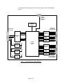
The CameraLink connectors are shielded, right angle, through hole, 26
position, female, SDR ( shrunk delta ribbon ) style connectors. Two such
connectors are provided on the card. The first connector is used for a
Channel #1 Base configuration while the second is used for either a
Channel #2 Base or Channel #1 Medium configuration. Note that in the
Channel #1 Medium configuration, the second connector’s CC[4:1] and
SerTC/SerTFG signals are unused.
Pin #
1
2
3
4
5
6
7
8
9
10
11
12
13
14
15
16
17
18
19
20
21
22
23
24
25
26
Cable name
Inner Shield
PAIR11PAIR10+
PAIR9PAIR8+
PAIR7+
PAIR6PAIR5+
PAIR4+
PAIR3+
PAIR2+
PAIR1+
Inner Shield
Inner Shield
PAIR11+
PAIR10PAIR9+
PAIR8PAIR7PAIR6+
PAIR5PAIR4PAIR3PAIR2PAIR1Inner Shield
Signal name
Inner Shield
CC4CC3+
CC2CC1+
SerTFG+
SerTCX3+
Xclk+
X2+
X1+
X0+
Inner Shield
Inner Shield
CC4+
CC3CC2+
CC1SerTFGSerTC+
X3XclkX2X1X0Inner Shield
Table 3 – Camera Link Connector Pin-out
Note that the Camera Link connector pin-out for the frame
grabber is 180 degrees rotated from the pin-out for the camera.
Page 69 of 75