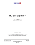
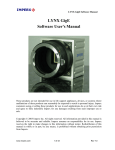
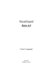
1
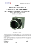
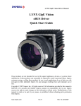
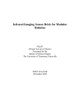
FrameLink
TM
User’s Manual
CONFIDENTIAL NOTICE:
Copyright ©2002, Imperx, Inc. All rights reserved.
Any unauthorized use, duplication or distribution of this document or any part thereof,
without the prior written consent of Imperx Corporation is strictly prohibited.
Imperx, inc.
6421 Congress Ave Ste. 204
Boca Raton, FL 33487 USA
DOC-0011-0002
Rev. RA07
06/24/05
CONFIDENTIAL & PROPRIETARY
Page 1 of 59
Revision History
RA01
RA02
Dec-9-2003
Feb-10-2004
J. Egri
J. Egri
Initial Release
RA03
Aug-25-2004
J. Egri
RA04
Dec-7-2004
J. Egri
RA05
May-05-2005
G. Angelone
RA06
Jun-08-2005
J. Egri
RA07
Jun-22-2005
J. Egri
Added Bayer-to-RGB support.
Added RGB Gain Control.
Updated 8-bit packing.
Added “Freeze preview window while capturing”
to Series of Frames and AVI dialogs.
Added DirectX installation instructions.
Changed Multiple Frame Settings dialog in Series
of Frames per software release v2.10
Added strobe inversion options to Camera
Configuration dialog per software release v2.11.
Modified software installation instructions to
support Install Shield.
Updated Chapter 4 to reflect v2.12 application
GUI.
Updated software installation instructions for
new driver install.
Added CC Control dialog to Chapter 4 to reflect
v2.13 of application GUI.
Updated software installation instructions.
Added Appendix A – Serial Communications.
Page 2 of 59
Table Of Contents
CHAPTER 1 - INTRODUCTION..............................................................................................................................5
FRAMELINK................................................................................................................................................................6
WHAT YOU NEED TO GET STARTED ...........................................................................................................................13
INSPECTING THE FRAMELINK PACKAGE ...................................................................................................................14
CHAPTER 2 – HARDWARE INSTALLATION ...................................................................................................15
CHAPTER 3 – SOFTWARE INSTALLATION ....................................................................................................16
SOFTWARE SUITE .....................................................................................................................................................16
SOFTWARE INSTALLATION FROM CD .......................................................................................................................18
SOFTWARE UPGRADE FROM WEB SITE .....................................................................................................................23
FIRMWARE UPGRADE FROM WEB SITE .....................................................................................................................28
CHAPTER 4 – USING THE FRAMELINK ...........................................................................................................29
RUNNING THE FRAMELINK APPLICATION ................................................................................................................30
MAIN WINDOW ........................................................................................................................................................31
CAMERA PARAMETERS DIALOG ...............................................................................................................................34
CAPTURE SETTINGS DIALOG ....................................................................................................................................41
CC CONTROL DIALOG ..............................................................................................................................................50
PLAYER DIALOG .......................................................................................................................................................54
CHAPTER 5 – ELECTRICAL INTERFACES......................................................................................................55
CAMERA LINK CONNECTOR .....................................................................................................................................56
PCMCIA/CARDBUS CONNECTOR ............................................................................................................................57
CHAPTER 6 - SPECIFICATIONS..........................................................................................................................58
APPENDIX A – SERIAL COMMUNICATIONS ..................................................................................................59
Page 3 of 59
Illustrations
Figure 1 – FrameLink Block Diagram...........................................................................................................................8
Figure 2 – Camera Link Interface..................................................................................................................................9
Figure 3 – EEPROM Programming In System............................................................................................................12
Tables
Table 1 – Image data bit-to-port assignments per the Camera Link specification.......................................................10
Table 2 – FrameLink Image data mapping into memory.............................................................................................10
Table 3 – Camera Link Connector Pin-out..................................................................................................................56
Table 4 – Cardbus Connector Pin-out..........................................................................................................................57
Page 4 of 59
Chapter 1 - Introduction
Introduction
This chapter outlines the key features of the Imperx
FrameLink card.
Page 5 of 59
FrameLink
The FrameLink frame grabber is a TYPE II PC Card with both a Camera
Link and Cardbus interface. It provides the ability to capture digital video
data from a ‘base configuration’ Camera Link interface and transfer that
data to host memory via a Cardbus ( PCI ) interface.
Functionality
•
Captures video data from the Camera Link interface, formats this data
and stores it into local SDRAM.
•
Retrieves the formatted data from the SDRAM and transfers it into
host memory via DMA over the Cardbus.
•
Provides a full-duplex asynchronous interface ( UART ) to/from an
attached device on the Camera Link’s serial interface.
•
Provides the host processor with the ability to configure the four
discrete Camera Control signals on the Camera Link interface.
Interfaces
Camera Link interface
The FrameLink provides a Camera Link interface that follows the ‘base
configuration’, as defined in the Camera Link standard, requiring a single
26 conductor connector/cable ( refer to Figure 2 ). The base configuration
consists of multiplexing 28 bits of video data into 4 LVDS data streams.
This data consists of 24 bits of pixel data along with 4 pixel qualifier
signals: ‘line valid’ strobe, ‘frame valid’ strobe, ‘data valid’ strobe and a
spare strobe ( for future use ). A phased-locked transmit clock is
transmitted in parallel with the data streams over a fifth LVDS link.
Additionally, four RS-644 LVDS streams are included for general purpose
camera control. These ‘camera control’ signals allow the frame grabber to
manipulate discrete controls within an attached camera. A bi-directional
asynchronous communications channel between the frame grabber and an
attached camera is also provided by means of two RS-644 LVDS pairs.
PCMCIA/CardBus interface
The FrameLink card complies with the TYPE II PC Card package
dimensions as defined in the PC Card Release 8.0 Standard. It includes a
30mm x 10mm extension area, used to house the CameraLink connector.
The FrameLink provides a 33 MHz 32 bit PCI Master/Target interface
Page 6 of 59
( Cardbus ) compliant with the PC Card Release 8.0 specification. This
interface provides a single ‘function’, as defined in the Cardbus
specification. The design does not support any memory mapped or I/O
mapped peripherals on card. Access to the FrameLink’s SDRAM devices
is achieved through DMA operations that move the data from the SDRAM
into host memory. The host cannot directly access the contents of the
SDRAM. The design supports host access into configuration registers,
DMA registers, local registers and CIS data via configuration space
accesses.
Page 7 of 59
32-bit PCI
Master/Slave
CardBus
Connector
68-pin Female
Figure 1 – FrameLink Block Diagram
Page 8 of 59
SDRAM
4Mx32
BGA-90
Configuration
EEPROM
EPC2
FPGA
ACEX EP1K100
BGA-484
3V-to-2.5V
converter
SDRAM
4Mx32
BGA-90
OSC
66Mhz
SerTFG
SerTC
CC1
CC2
CC3
CC4
PortA
PortB
PortC
Strobes
Clk
8
8
8
4
ByteBlaster
Programming
Header
Camera Link
Transceiver
2
2
2
2
2
2
2
2
2
SerTFG 2
SerTC 2
CC1
CC2
CC3
CC4
X0
X1
X2
X3
Xclk
Camera Link
Connector
26-pin Female
A functional block diagram of the FrameLink card is illustrated in
Figure 1.
A functional block diagram of the Camera Link interface is illustrated in
Figure 2.
15
12
12
X0+
Pair 1+
2
25
Pair 1-
16
11
25
11
X0-
X1+
Pair 2+
3
24
Pair 2-
17
10
24
10
X1-
X2+
Pair 3+
4
23
Pair 3-
19
8
23
8
X2-
X3+
Pair 5+
X3-
26-pin Female
MDR Connector
18
21
26-pin Male
MDR Connector
21
Pair 5-
26-pin Male
MDR Connector
6
9
9
Xclk+
22
22
Xclk-
15
15
CC4+
2
2
CC4-
3
3
CC3+
16
16
CC3-
17
17
CC2+
4
4
CC2-
5
5
CC1+
18
18
CC1-
6
6
SerTFG+
19
19
SerTFG-
20
20
SerTC+
7
7
SerTC-
Rx17
Port C7
Rx16
Rx22
Port C6
Port C5
Rx21
Rx20
Port C4
Port C3
Rx19
Port C2
Rx18
Rx15
Port C1
Port C0
Rx11
Rx10
Port B7
Port B6
Rx14
Port B5
Rx13
Rx12
Port B4
Port B3
Rx9
Rx8
Port B2
Port B1
Rx7
Port B0
Rx5
Rx27
Port A7
Port A6
Rx6
Rx4
Port A5
Port A4
Rx3
Port A3
Rx2
Rx1
Port A2
Port A1
Rx0
Port A0
Rx26
Rx25
DVAL
FVAL
Rx24
LVAL
Rx23
spare
Pair 4+
RxCLKOut
5
Pair 4-
12
Pair 11+
25
CC4
Pair 11-
24
Pair 10+
11
CC3
Pair 10-
10
Pair 9+
23
CC2
Pair 9-
22
Pair 8+
9
CC1
Pair 8-
21
Pair 7+
SerTFG
8
Pair 7-
7
Pair 6+
SerTC
20
Pair 6-
1
Inner Shield
1
1
13
14
Inner Shield
Inner Shield
13
14
13
14
Inner Shield
26
26
26
Camera Link
Cable
FrameLink
Frame Grabber
Figure 2 – Camera Link Interface
Page 9 of 59
Clock
Video Capture
The video capture engine is responsible for receiving video pixel data and
qualifiers from the Camera Link transceivers, formatting the data and
transferring it into on-board memory. The data that it receives from the
Camera Link transceivers is formatted per Table 1. Ten different modes of
operation are supported as indicated in the table. The video capture engine
translates this data into longwords ( 32 bits ), as defined in Table 2, in
order to use the Cardbus bandwidth more efficiently and conserve memory
space. Table 2 reflects how the data will appear in host memory. In the
case of the single tap and dual tap 8 bit modes, the module packs four
pixels into each longword. In the case of the other modes, excluding 3x8
and RGB, the module packs two pixels into each longword.
Por t C
Por t B
c7 c6 c5 c4 C3 c2 c1 c0 b7 b6 b5 b4 b3 b2 b1 b0 a7
A7
B7 B6 B5 B4 B3 B2 B1 B0 A7
C7 C6 C5 C4 C3 C2 C1 C0 B7 B6 B5 B4 B3 B2 B1 B0 A7
a6
A6
A6
A6
a5
A5
A5
A5
Por t A
a4 a3
A4 A3
A4 A3
A4 A3
a2
A2
A2
A2
a1
A1
A1
A1
a0
A0
A0
A0
MODE
1x8
2x8
3X8
A9 A8 A7 A6 A5 A4 A3 A2 A1 A0
A9 A8 A7 A6 A5 A4 A3 A2 A1 A0
1x10
2x10
A11 A10 A9 A8 A7 A6 A5 A4 A3 A2 A1 A0
B7 B6 B5 B4 B3 B2 B1 B0 B11 B10 B9 B8 A11 A10 A9 A8 A7 A6 A5 A4 A3 A2 A1 A0
1x12
2x12
A13 A12 A11 A10 A9 A8 A7 A6 A5 A4 A3 A2 A1 A0
1x14
A15 A14 A13 A12 A11 A10 A9 A8 A7 A6 A5 A4 A3 A2 A1 A0
1x16
B7 B6 B5 B4 B3 B2 B1 B0
B9 B8
BL7 BL6 BL5 BL4 BL3 BL2 BL1 BL0 GR7 GR6 GR5 GR4 GR5 GR2 GR1 GR0 RD7 RD6 RD5 RD4 RD3 RD2 RD1 RD0 RGB (1x24)
Table 1 – Image data bit-to-port assignments per the Camera Link specification
d31 d30 d29 d28 d27 d26 d25 d24 d23
A7 A6 A5 A4 A3 A2 A1 A0 A7
B7 B6 B5 B4 B3 B2 B1 B0 A7
C7
d22
A6
A6
C6
d21
A5
A5
C5
d20
A4
A4
C4
d19
A3
A3
C3
d18
A2
A2
C2
d17
A1
A1
C1
d16
A0
A0
C0
d15
A7
B7
B7
d14
A6
B6
B6
d13
A5
B5
B5
d12
A4
B4
B4
d11
A3
B3
B3
d10
A2
B2
B2
d9
A1
B1
B1
d8
A0
B0
B0
d7
A7
A7
A7
d6
A6
A6
A6
d5
A5
A5
A5
d4
A4
A4
A4
d3
A3
A3
A3
d2
A2
A2
A2
d1
A1
A1
A1
d0
A0
A0
A0
MODE
1x8
2x8
3X8
A9 A8 A7 A6 A5 A4 A3 A2 A1 A0
B9 B8 B7 B6 B5 B4 B3 B2 B1 B0
A9 A8 A7 A6 A5 A4 A3 A2 A1 A0 1x10
A9 A8 A7 A6 A5 A4 A3 A2 A1 A0 2x10
A11 A10 A9 A8 A7 A6 A5 A4 A3 A2 A1 A0
B11 B10 B9 B8 B7 B6 B5 B4 B3 B2 B1 B0
A11 A10 A9 A8 A7 A6 A5 A4 A3 A2 A1 A0 1x12
A11 A10 A9 A8 A7 A6 A5 A4 A3 A2 A1 A0 2x12
A13 A12 A11 A10 A9 A8 A7 A6 A5 A4 A3 A2 A1 A0
A13 A12 A11 A10 A9 A8 A7 A6 A5 A4 A3 A2 A1 A0 1x14
A15 A14 A13 A12 A11 A10 A9 A8 A7 A6 A5 A4 A3 A2 A1 A0 A15 A14 A13 A12 A11 A10 A9 A8 A7 A6 A5 A4 A3 A2 A1 A0 1x16
RD7 RD6 RD5 RD4 RD3 RD2 RD1 RD0 GR7 GR6 GR5 GR4 GR3 GR2 GR1 GR0 BL7 BL6 BL5 BL4 BL3 BL2 BL1 BL0 RGB
Table 2 – FrameLink Image data mapping into memory
Pixel Buffering
The pixel data formatted by the video capture engine is stored into two
Page 10 of 59
on-board 4Mx32 SDRAM devices. This memory serves as a local store for
formatted video pixel data. Each SDRAM will buffer a single frame’s
worth of data, supporting a maximum frame size of 8 million pixels/frame
in all modes except RGB. In the RGB mode, the maximum frame size
supported is 4 million pixels. The SDRAMs are managed by an
independent pair of controllers, implemented in the FPGA, supporting
concurrent operation. The two SDRAMs are utilized in a ping-pong
fashion such that while one is being filled with new pixel data, the other is
being emptied via DMA into host memory.
DMA
The DMA engine is responsible for reading formatted pixel data from the
on-board SDRAM devices and transferring them into host memory via the
Cardbus interface. An intelligent scatter-gather method is utilized,
providing for an efficient use of the Cardbus bandwidth. The use of noncontiguous 4Kbyte buffers provides support for the Windows operating
system’s memory allocation model.
Serial Interface
A bi-directional Universal Asynchronous Receiver Transmitter ( UART )
is provided for the Camera Link serial interface. It transmits and receives
ASYNC formatted characters with 1 Start bit, 8 data bits, no parity and 1
Stop bit. The baud rate of this interface can be configured by the user to be
any one of a set of standard bit rates ranging from 4800 to 115.2K bits per
second. A software interface to the UART is provided by means of a
Camera Link compliant ‘clservce.dll’ file.
Camera Control
The FrameLink card provides four discrete camera control bits per the
Camera Link specification. These bits can be configured by the user via
the FrameLink application GUI.
FPGA
The heart of the FrameLink is a dense Field Programmable Gate Array
( FPGA ). This FPGA implements all of the functions related to video
data capture, storage and DMA. The firmware contents of the FPGA can
be upgraded while in the field by following the instruction outlined in
Section 3 of this document entitled ‘Firmware Upgrade from Web Site’.
In System Programming:
The FrameLink design supports ISP programming during operation. This
capability is useful when the FPGA code needs to be upgraded and the
unit is at a remote customer location. The programming is accomplished
using a JamPlayer utility, which runs on the host PC. The JamPlayer
utility downloads a new FPGA image into the EEPROM via the Cardbus
interface. The FPGA provides a set of I/O pins which are connected to the
EEPROM’s JTAG interface. The JamPlayer utility toggles these I/O pins,
which are mapped into a register in configuration space, and thus can
communicate with the EEPROM’s JTAG controller and affect a
programming operation.
Page 11 of 59
I/O
I/O
I/O
Cardbus
Interface
I/O
FPGA
TCK
TMS
TDI
Configuration
EEPROM
Cardbus
Connector
TCK
TMS
ISP
TDO
TDI
TDO
FrameLink Card
Figure 3 – EEPROM Programming In System
Page 12 of 59
Not
Used
PC
w/JamPlayer
What you need to get started
To begin using the FrameLink card, you need the following:
•
A computer with a PCMCIA slot that is Cardbus compliant.
•
Microsoft Windows XP or 2000 software.
•
A computer with a relatively up to date Cardbus-to-PCI chipset
( sometimes referred to as a ‘Cardbus Controller’ ). You can determine
which chipset your laptop uses by looking in:
Control Panel – System – Hardware – Device Manager – PCMCIA
Adapters
These chipsets are recommended because they generally offer better
performance in terms of DMA transfer rates:
TI PCI-1520
TI PCI-4510
These chipsets are discouraged because of their poor DMA
performance:
O2 Micro OZ6912
TI PCI-1225
•
A computer with at least 256M bytes of RAM.
•
A CD drive, and a hard disk on which to install the FrameLink
software.
Page 13 of 59
Inspecting the FrameLink package
When you unpack your FrameLink package, you should visually inspect
all of its contents. If something is missing or damaged, contact your
Imperx representative.
Package contents
You should have received the following items:
•
The FrameLink PCMCIA card
•
A metal ‘strain relief’ bracket
•
A CD with the FrameLink software suite
•
A ‘Quick Start’ installation guide
•
A ‘User’s Manual’ ( this document )
Page 14 of 59
Chapter 2 – Hardware Installation
Hardware Installation
Installing the FrameLink card is as simple as plugging it into an available
PCMCIA slot on your computer. Note that the card should be plugged in
with the CameraLink connector facing up and away from the computer.
Page 15 of 59
Chapter 3 – Software Installation
Software Installation
This chapter explains how to install the FrameLink software.
Software Suite
The FrameLink software suite consists of the following files:
Windows XP and 2000 application files:
( located in c:\Program_Files\ImperX\FrameLink\ )
AMCap.exe
clservce.dll
console.exe
ijl20.dll
VCECLB.dll
VCECLB_app.chm
VCECLB_app.exe
VCECLB-LS_app.exe
VceComX.exe
- DirectX sample application
- CameraLink serial interface library
- console program ( for debug purposes )
- Intel JPEG encoding/decoding library
- FrameLink library
- FrameLink help file
- FrameLink Area Scan application
- FrameLink Line Scan application
- Virtual COM port emulator
Windows XP and 2000 driver files:
( located in c:\Program_Files\ImperX\FrameLink\Drivers\WDM\ )
vceclb.sys
vceclb.inf
ipxinstdrv.exe
- FrameLink WinXP/2000 driver file
- FrameLink WinXP/2000 driver info file
- WDM Streaming installation program
Page 16 of 59
Streaming Kernel Driver ( DirectX ) files:
( located in c:\Program_Files\ImperX\FrameLink\Drivers\DirectX\ )
Vceclbks.sys
Vceclbks.inf
VceClbKs.ax
- FrameLink WDM Streaming driver
- FrameLink WDM Streaming info file
- WDM Streaming driver’s properties plugin
Documentation files:
( located in c:\Program_Files\ImperX\FrameLink\Doc\ )
FrameLink_Users_Manual.pdf - User manual document
FrameLinkSpec.pdf
- Technical datasheet
History_drv.txt
- WDM driver change description file
History_ks.txt
- KS driver change description file
History_app.txt
- Application change description file
Cam Files:
( located in c:\Program_Files\ImperX\FrameLink\Cam_Files\ )
IPX folder
MDC folder
LYNX folder
- FrameLink configuration files for Imperx’
IPX series of cameras
- FrameLink configuration files for Imperx’
MDC series of cameras
- FrameLink configuration files for Imperx’
LYNX series of cameras
Note that our FrameLink application program was created using our SDK
( software developers kit ). Our SDK is a separately purchased product
and is not included in the standard FrameLink software suite that comes
with the card. For more information on the SDK, please visit our web site
at http://www.imperx.com/sdk/index.php or call us toll free at 1-877-863-1654.
Page 17 of 59
Software Installation from CD
Use the following steps to install the FrameLink software supplied on a
CD:
1.
If a version of FrameLink was previously installed on this
machine, then you must first remove it:
To remove the application files:
1.1
1.2
1.3
1.4
1.5
1.6
1.7
1.8
1.9
2.
Left mouse click on “Start”
Left mouse click on “Settings”.
Left mouse click on “Control Panel”.
Double left mouse click on “Add or Remove Programs”.
Left mouse click on “FrameLink”.
Left mouse click on “Remove”.
If the ‘FrameLink – InstallShield Wizard’ pops-up,
do the following:
If not, go to step 1.8
Left mouse click on ‘Remove’.
Click ‘Next’.
Click ‘Yes’.
Click ‘Finish’.
Left mouse click on “Yes”.
Left mouse click on “Close”.
After having removed a previous version or if a version of
FrameLink was NOT previously installed on this machine then:
The first step is to install the application files:
2.1
2.2
2.3
2.4
Insert the FrameLink CD into the appropriate drive; the
setup.exe file will run automatically. Note: If it does not
start automatically, left mouse click on to “Start”, “Run”,
enter or browse to “(CD drive): setup.exe” and click
“OK”.
Wait for the “FrameLink - InstallShield Wizard” screen to
appear.
Follow the on-screen instructions.
For Windows XP, the following message will appear:
Page 18 of 59
For Windows 2000, the following message will appear:
2.5
2.6
Click “Continue Anyway” for XP, “Yes” for 2000.
When the following message appears, choose if you
would like to register online by left clicking on “Yes”
or “No”.
If you choose “Yes”, follow the on-screen instructions.
Page 19 of 59
2.7
When prompted, select ”Yes, I will restart my
computer now”.
After restarting the computer a New Hardware Found screen
will come up: ( the FrameLink card must be installed to
perform the following steps )
Steps 2.8 through 2.14 are for Windows XP. For Windows 2000,
go to Step 2.15
2.8
2.9
Wait for the system to prompt you with a “Found
New Hardware Wizard” dialog box.
Under certain conditions, the following message
may appear:
If this message appears, click “No, not this time”, then
“Next”.
Page 20 of 59
2.10
When the following message appears, select “Install
the software automatically (Recommended)”, then left
click “Next”.
2.11
For Windows XP, the following message will appear:
2.12
2.13
Click “Continue Anyway” to continue.
When “Click Finish to close the wizard” appears, Left
click on “Finish”.
This completes the installation for Windows XP.
2.14
To install the WDM driver for Windows 2000:
2.15
Wait for the system to prompt you with a “Found New
Hardware Wizard” dialog box.
Page 21 of 59
2.16
Left click “Next” to continue. The following message will
appear:
Click “Yes” to continue.
2.17
2.18
2.19
Click “OK” , then either enter or browse to:
C:\Program Files\ImperX\FrameLink\Drivers\WDM
Click “OK”
This completes the installation for Windows 2000.
Page 22 of 59
Software Upgrade from Web Site
New application and/or driver software may be released periodically to
reflect improvements and/or functionality added to the FrameLink. You
can retrieve these updates by visiting the download page of our web
site at http://www.imperx.com/frame_grabbers/camera_link/FrameLink_downloads.php
Use the following steps to install newly released application software:
3.1
3.2
3.3
3.4
3.5
3.6
Uninstall all application files by following the instructions in
step 1. of the ‘Software Installation from CD’ section.
Download the FrameLink_Installer.exe file from the
Imperx web site to a new folder on your PC ( we will use
the folder C:\new_FrameLink as an example ).
Left mouse click on “Start”, “Run”, enter or browse to
“C:\new_FrameLink\FrameLink_Installer.exe”.
Left mouse click on “Open”, then “OK”.
Follow the on-screen instructions.
For XP, when the following message appears, left click
“Continue Anyway”
Page 23 of 59
For Windows 2000, when the following message
appears, click “Yes”.
3.7
When the following message appears, choose if you
would like to register online by left clicking on “Yes”
or “No”.
If you choose “Yes”, follow the on-screen instructions.
3.8
4.
When prompted, select ”Yes, I want to restart my
computer now” and left click “Finish”.
After having successfully installed the newly released application
software, use the following steps to install a newly released WDM
driver for Windows XP ( for Windows 2000 go to step 5. ):
4.1 Wait for the system to prompt you with a “New Hardware
Found” dialog box.
Page 24 of 59
4.2 Under certain conditions, the following message
may appear:
If this message appears, click “No, not this time”, then
“Next”.
4.3 When the following message appears, select “Install the
software automatically (Recommended)”, then left click
“Next”.
Page 25 of 59
4.4
For XP, when the following message appears, left click
“Continue Anyway”.
4.5
When “Click Finish to close the wizard” appears, Left click
on “Finish”.
This completes the installation for Windows XP.
4.6
5.
After having successfully installed the newly released application
software, use the following steps to install a newly released WDM
driver for Windows 2000:
5.1
Wait for the system to prompt you with a “Found New
Hardware Wizard” dialog box.
5.2
Left click “Next” to continue. The following message will
appear:
Page 26 of 59
5.3
Click “Yes” to continue.
5.4
Click “OK” , then either enter or browse to:
C:\Program Files\ImperX\FrameLink\Drivers\WDM
Click “OK”.
This completes the installation for Windows 2000.
5.5
5.6
Page 27 of 59
Firmware Upgrade from Web Site
Your newly received FrameLink card has been programmed in the factory
with the latest firmware prior to shipping. New firmware, however, may
be released periodically to reflect improvements and/or functionality
added to the FrameLink FPGA. You can retrieve these updates by visiting
the download page of our web site at
http://www.imperx.com/frame_grabbers/camera_link/FrameLink_downloads.php
Use the following steps to install newly released firmware:
1.
Download and unzip the firmware patch ( .zip ) file to a folder on
your PC ( we will use C:\fw_patch as an example ).
2.
If you haven't previously installed the JamPCI drivers then:
2.1
Left mouse click on to “Start”, “Run”, enter
“C:/fw_patch/loadsys.bat” and click ”OK”.
2.2
Wait until "Press any key to continue . . ." message appears.
2.3
Press any key to exit batch file.
3.
Insert the FrameLink card into the laptop. Note that if your system
has two PCMCIA slots, then you must insert the card into the slot
in which it was placed during the original driver installation.
4.
If the system prompts you with a “New Hardware Found” dialog
box, press “Cancel”.
5.
Note: DO NOT POWER DOWN OR REMOVE CARD
WHILE PROGRAMMING IS IN PROGRESS!
6.
Left mouse click on “Start”, “Run”, enter
“C:/fw_patch/FrameLink_patch_x_y.bat” and click ”OK”.
Note that ‘x_y’ refers to the revision number ( i.e. 2.0 ).
7.
Wait until "Press any key to continue . . ." message appears.
8.
If line above it reads "Exit code = 0...Success" then proceed with
installation, otherwise contact [email protected].
9.
Press any key to exit batch file.
10.
You must either reboot the PC or remove and then reinsert the
FrameLink card in order for the changes to take effect
Page 28 of 59
Chapter 4 – Using the FrameLink
Using the FrameLink
This chapter contains information on how to configure and use the
FrameLink card.
Page 29 of 59
Running the FrameLink Application
The VCECLB_app.exe program supplied with the FrameLink card is a
stand-alone Windows based application. It provides an easy to use
graphical user interface ( GUI ), allowing the user to configure the
FrameLink card and to view, record and playback video data received
from the CameraLink interface. The application consists of a
main window as well as ‘Camera Configuration’, ‘Control Panel’
and ‘Player’ dialog windows.
Launching
Application
To launch the FrameLink application, simply double left mouse click on
the ‘FrameLink application’ icon on the desktop.
Note
In the remainder of this chapter, references to ‘clicking’ on objects in the
GUI refers to the left mouse button.
Page 30 of 59
Main Window
When the VCECLB_app.exe program is executed, a main window titled
‘FrameLink™ Application’ will appear. The main window provides the
primary area for viewing real-time images received from the camera. This
window can be sized and moved to suit your needs. When image viewing
is active, the size of this window will be automatically scaled as a function
of the camera parameters ( i.e. pixels/ line and lines/frame ) specified in
the ‘Camera Parameters’ dialog.
File
Zoom
Clicking on this item reveals a pull-down menu with two options:
‘Player’ and ‘Exit’.
Player
This option opens the ‘Player Dialog’ and ‘Player Control’
windows.
Exit
Clicking on this option causes the program to terminate.
Reveals a pull-down menu which allow the user to select the image
scaling factor. The image scaling factor determines the size of the
display window and the captured image. Changing from one scale
to another scale automatically updates the display window and
image size.
Page 31 of 59
Control Panel
Clicking on this item reveals a pull-down menu with the following
options:
Capture
Settings
Selecting this item causes the ‘Capture Settings’ dialog to appear.
Alternatively, Ctrl-S can be used to open/close this dialog.
Camera
Parameters
Selecting this item causes the ‘Camera Parameters’ dialog to
appear. Alternatively, Ctrl-P can be used to open/close this dialog.
RGB
Gain
Select this option when you wish to adjust each of the RGB color
components. This option is only available if ‘Bayer’ or ‘RGB’ is
selected in the ‘video type’ field of the ‘Camera Parameters’
dialog. Clicking on this button causes the ‘RGB Gain Control’
dialog window to open. Alternatively, Ctrl-R can be used to
open/close this dialog.
CC
Control
Selecting this item causes the ‘CC Control’ dialog to
appear. Alternatively, Ctrl-C can be used to open/close this dialog.
Camera
This button lets you choose which camera you would like to use. Note that
this option is only viable for the FrameLink-JFLEX dual port card. It has
no effect for the standard FrameLink.
Start/Stop
Grab
This button will toggle between ‘Start Grab’ and ‘Stop Grab’ every time
the user clicks on it. Clicking on ‘Start Grab ‘enables the FrameLink’s
DMA engine and causes the main window to display live images received
from the camera. Clicking on ‘Stop Grab’ disables the DMA engine and
causes the display to freeze.
Page 32 of 59
Start/Stop
Capture
This button will toggle between ‘Start Capture’ and ‘Stop Capture’
every time the user clicks on it. Clicking on ‘Start Capture‘ starts the
process of recording the images to disk. The options set in the ‘Capture
Options’ field determine what, how and when actual recording is
performed. Clicking on ‘Stop Capture’ causes recording to stop.
Help
Clicking on this item reveals a pull-down menu with two options:
‘About’ and ‘Help Manual’.
About
Clicking on this option causes version information to be displayed
including release identifiers for the application software, library,
driver and firmware. This information should be provided to
Imperx technical support personnel during a service call.
Help
Manual
Clicking on this option causes an interactive point-and-click style
help manual to be displayed. The help manual provides a summary
description of all GUI controls and fields.
Status
Indicators
On the bottom of the window are two status indicators: ‘Camera’ status
and ‘DMA’ status.
Camera
Status
Displays the real-time status of the attached camera as being either
‘online’ or ‘offline’. ‘Online’ indicates that the camera is powered
on, attached and providing a video clock via the CameraLink
interface. ‘Offline’ indicates that the FrameLink card is not
receiving a video clock from the camera either because the camera
is powered off or the CameraLink cable is disconnected.
DMA
Status
Displays the real-time status of the DMA process as being either
‘active’ or ‘inactive’. ‘Active’ indicates that the user has
commanded the FrameLink to acquire video data by clicking on
the ‘start grab’ button and that the camera is providing valid
framing ( FVAL signal toggling ). ‘Inactive’ indicates that either
the user has commanded the FrameLink to stop acquiring video
data by clicking on the ‘stop grab’ button or that grabbing is
enabled but the camera is not providing valid framing ( no FVAL
signal )
Page 33 of 59
Camera Parameters Dialog
When the VCECLB_app.exe program is executed, a ‘Camera
Parameters’ dialog will appear. The Camera Parameters screen
allows the user to program the FrameLink card with the operating
parameters of the attached camera. For the FrameLink card to be
able to properly acquire and display images from an attached camera,
the settings entered into this screen must match the parameters of the
camera.
Manufacturer
Model
Description
These text fields allow the user to record the vendor and part number of
the attached camera. This text, along with all of the other settings, can then
be saved as a .CAM file on the PC for later retrieval.
Load
Loads a previously saved camera configuration file. Clicking on this box
will cause a Windows ‘browse’ box to appear. The user can then browse
to the folder and file he wishes to open. The program will then open the
selected file, parse it and populate the fields in the GUI.
Save
Saves the current GUI fields as a camera configuration file. Clicking on
this box will cause a Windows ‘browse’ box to appear. The user can then
browse to a folder and enter a file name. The program will then create a
.CAM file using the values in the GUI’s fields and write it to the disk.
Page 34 of 59
Dimension
These fields specify the geometry of the attached camera and instruct the
FrameLink on how to reconstruct a received image.
Width (pixels):
These fields specify the total number of pixels per line. The
Camera Link standard defines a line as being a series of pixels
enveloped by the LVAL strobe and qualified by the DVAL strobe.
Cameras generally provide some leading and trailing dummy
pixels before and after a set of valid pixels. Most cameras can
disqualify these dummy pixels by negating the DVAL signal. For
cameras that do not disqualify the dummy pixels, the FrameLink
has to be told the number of pre-valid, valid and post-valid pixels
in order to properly construct an image.
Pre-valid
Specifies the number of leading pixels prior to any
valid pixels. The FrameLink will exclude these
pixels from the displayed/captured image.
Valid
Specifies the number of valid pixels. The
FrameLink will include these pixels in the
displayed/captured image.
Post-valid
Specifies the number of trailing pixels following
any valid pixels. The FrameLink will exclude these
pixels from the displayed/captured image.
Height (lines):
These fields specify the total number of lines per frame. The
Camera Link standard defines a frame as being a series of lines
enveloped by the FVAL strobe. Cameras can sometimes provide
some leading and trailing dummy lines before and after a set of
valid lines. Most cameras can disqualify these dummy lines by
negating the FVAL signal. For cameras that do not disqualify the
dummy lines, the FrameLink has to be told the number of prevalid, valid and post-valid lines in order to properly construct an
image.
Pre-valid
Specifies the number of leading lines prior to any
valid lines. The FrameLink will exclude these lines
from the displayed/captured image.
Valid
Specifies the number of valid lines. The FrameLink
will include these lines in the displayed/captured
image.
Post-valid
Specifies the number of trailing lines following
any valid lines. The FrameLink will exclude these
Page 35 of 59
lines from the displayed/captured image.
Taps
Specifies the number of taps ( channels ) of video data provided by the
attached camera.
Dual Mode
This field specifies the order in which the pixels are received from the
Camera when operating in the dual tap mode. Two formats are supported:
‘Horizontal sequential’ and ‘Horizontal interlaced’.
Horizontal
Sequential
This should be selected when the camera delivers pixels in the
following order ( where n = total number of pixels in the line ):
TAP #1
Pixel #
1
Pixel #
2
Pixel #
(n/2) -1
Pixel #
n/2
TAP #2
Pixel #
n
Pixel #
n-1
Pixel #
(n/2)+2
Pixel #
(n/2)+1
For example: For a camera with 1004 pixels/line in Horizontal Sequential
dual progressive mode:
TAP #1
Pixel #
1
Pixel #
2
Pixel #
501
Pixel #
502
TAP #2
Pixel #
1004
Pixel #
1003
Pixel #
504
Pixel #
503
Page 36 of 59
Horizontal
Interlaced
This should be selected when the camera delivers pixels in the
following order ( where n = total number of pixels in the line )
TAP #1
Pixel #
1
Pixel #
3
Pixel #
n-3
Pixel #
n-1
TAP #2
Pixel #
2
Pixel #
4
Pixel #
n-2
Pixel #
n
For example: For a camera with 1004 pixels/line in Horizontal Interlaced
dual progressive mode:
TAP #1
Pixel #
1
Pixel #
3
Pixel #
1001
Pixel #
1003
TAP #2
Pixel #
2
Pixel #
4
Pixel #
1002
Pixel #
1004
Reverse Tap
Configures the FrameLink to reverse the pixel order of the displayed
image ( mirror left-to-right or right-to-left ) of either Tap #1 , Tap #2 or
both taps.
Page 37 of 59
Strobes
Specifies how to treat the Camera Link strobes, where ‘DVAL’ is data
valid, ‘LVAL’ is line valid and ‘FVAL’ is frame valid.
Ignore DVAL
Instructs the FrameLink card to ignore the ‘DVAL’ signal received
from the CameraLink interface. Pixel capture will be qualified with
the ‘FVAL’ and ‘LVAL’ signals only.
Invert DVAL
Instructs the FrameLink card to invert the ‘DVAL’ signal received
from the CameraLink interface prior to processing it.
Invert LVAL
Instructs the FrameLink card to invert the ‘LVAL’ signal received
from the CameraLink interface prior to processing it.
Invert FVAL
Instructs the FrameLink card to invert the ‘FVAL’ signal received
from the CameraLink interface prior to processing it.
Video Type
Specifies the video mode as either or monochrome, Bayer or RGB ( 24
bit ).
Camera
Bit Depth
Specifies the number of bits per pixel when the video type is
monochrome. When the video type is RGB, the depth is fixed at 24 bits.
Control Bits
Specifies the state of the four camera control signals ( CC1 – CC4 ) of the
CameraLink interface. An unchecked box represents a negated signal
( logic-0 ), while a checked box represents an asserted signal ( logic-1 )
Bayer Start
Specifies the starting pixel in the bayer pattern as provided by the camera.
This selection is typically required when a camera is operated with an
‘area of interest’ feature enabled. For the following examples, assume that
‘n = number of pixels/line’ and ‘m = number of lines’ then:
Pattern #1
Use this selection when the camera provides the following pattern:
Line
1
2
3
4
:
m-1
m
1
G
B
G
B
2
R
G
R
G
3
G
B
G
B
G
B
R
G
G
B
Pixel
4
R
G
R
G
R
G
…
n-1
G
B
G
B
n
R
G
R
G
G
B
R
G
An example of this is when the camera is operated in a normal
Page 38 of 59
mode or when its horizontal window starts on an odd pixel and
its vertical window starts on an odd line.
Pattern #2
Use this selection when the camera provides the following pattern:
Line
1
2
3
4
:
m-1
m
1
R
G
R
G
2
G
B
G
B
3
R
G
R
G
R
G
G
B
R
G
Pixel
4
G
B
G
B
…
G
B
n-1
R
G
R
G
n
G
B
G
B
R
G
G
B
An example of this is when the camera’s horizontal window starts
on an even pixel and its vertical window starts on an odd line.
Pattern #3
Use this selection when the camera provides the following pattern:
Line
1
2
3
4
:
m-1
m
1
B
G
B
G
2
G
R
G
R
3
B
G
B
G
B
G
G
R
B
G
Pixel
4
G
R
G
R
…
G
R
n-1
B
G
B
G
n
G
R
G
R
B
G
G
R
An example of this is when the camera’s horizontal window starts
on an odd pixel and its vertical window starts on an even line.
Pattern #4
Use this selection when the camera provides the following pattern:
Line
1
2
3
4
:
m-1
m
1
G
R
G
R
2
B
G
B
G
3
G
R
G
R
G
R
B
G
G
R
Pixel
4
B
G
B
G
B
G
…
An
of this is when the camera’s horizontal window starts
Page 39 of 59
n-1
G
R
G
R
n
B
G
B
G
G
R
B
G
example
on an even pixel and its vertical window starts on an even line.
SerialLink
BaudRate
Specifies the data transfer speed of the CameraLink’s serial interface.
Clicking on this box causes a pull-down menu to appear. The user can
then select the desired baud rate from among the choices presented,
ranging from 9600 to 115,200 bits per second. This setting must match the
camera’s requirements.
Apply
Causes the application to apply the current settings to the FrameLink card.
Start/Stop
Grab
This button will toggle between ‘Start Grab’ and ‘Stop Grab’ every time
the user clicks on it. Clicking on ‘Start Grab’ enables the FrameLink’s
DMA engine and causes the main window to display live images received
from the camera. Clicking on ‘Stop Grab’ disables the DMA engine and
causes the display to freeze.
Close
This button will hide the Camera Parameters dialog screen. You can
invoke it again by either hitting Ctrl-P or by selecting it from the Control
Panel pull-down menu.
Page 40 of 59
Capture Settings Dialog
This dialog can be invoked by either hitting Ctrl-S or by selecting it from
the Control Panel pull-down menu. This dialog gives the user complete
control over image storage. The window can be moved anywhere around
the screen to suit your needs.
Start/Stop
Capture
This button will toggle between ‘Start Capture’ and ‘Stop Capture’
every time the user clicks on it. Clicking on ‘Start Capture‘ starts the
process of recording the images to disk. The options set in the ‘Capture
Options’ field determine what, how and when actual recording is
performed. Clicking on ‘Stop Capture’ causes recording to stop.
Close
This button will hide the Capture Settings Dialog screen. You can
invoke it again by either hitting Ctrl-S or by selecting it from the Control
Panel pull-down menu.
Image Format
When recording images to disk, this option selects the format, ‘BMP’,
‘JPEG’ or ‘TIFF’, that the image will be saved in. Selecting ‘JPEG’
activates a compression slider. ‘Best Quality’ provides the least
compression while ‘Smallest File’ provides the most compression.
Pixel Padding
Pixel padding defines the way in which TIFF files are created. Since a
TIFF file uses 16 bits to represent each pixel and cameras can produce less
than 16 bit pixels, the pixel padding option is provided. ‘Left’ pixel
padding means that 16 bit TIFF data is produced by appending zeros to the
MSB bits of the pixel data. For example, for a 12 bit pixel the resultant 16
bit TIFF data is “0,0,0,0,p12, p11….p2,p1” where p12..p1 represent the 12
Page 41 of 59
bit pixel. Left padding is useful when the user wishes to post-process the
TIFF data. ‘Right’ pixel padding means that 16 bit TIFF data is produced
by shifting the pixel data left and appending zeros to the LSB bits of the
pixel data. For example, for a 12 bit pixel the resultant 16 bit TIFF data is
“p12, p11….p2,p1,0,0,0,0”. Right padding is useful when the user wishes
to view the TIFF data using a standard TIFF viewer program.
Capture Options
Determines how, when and where images are recorded to disk. Three
choices are provided: ‘Single Frames’, ‘Series of Frames’ and ‘AVI
Video’. Clicking on each option opens a new dialog window providing
additional options.
Single Frames
Select this option when you wish to record one frame only.
Clicking on this button causes the ‘Single Frame Settings’
dialog window to open.
Path/Filename
This text field allows you to provide a path and
filename for the recorded image file. Clicking on
the ‘…’ box will cause a Windows ‘browse’ box to
appear. The user can then browse to a folder and
enter a file name. The filename extension, .BMP or
.JPG, will automatically be added depending on the
image format chosen and therefore you do not need
to include the filename extension.
Text Overlay
Enabling ‘Insert Date and Time’ automatically
places the date and time on each image recorded.
Date and time formats are the same as those used on
your computer. Enabling ‘Insert Text Message’
allows you to enter a text string to be automatically
overlayed on each image recorded. Clicking on
‘Position’ causes a pull-down menu to appear
Page 42 of 59
which defines the placement position of the
date/time/text message within the image. Available
options include: Top-Left, Top-Center, Top-Right,
Bottom-Left, Bottom-Center and Bottom-Right.
Accept
Clicking on this causes the entries made to the
various fields to be accepted and then closes the
‘Single Frame Settings’ dialog window.
Cancel
Clicking on this causes the entries made to the
various fields to be rejected and then closes the
‘Single Frame Settings’ dialog window.
Series of Frames Select this option when you wish to record multiple frames.
Clicking on this button causes the ‘Series of Frames Settings’
dialog window to open.
Path/Filename
This text field allows you to provide a path to a
folder where the recorded image files will be saved
Page 43 of 59
to. Clicking on the ‘…’ box will cause a Windows
‘browse’ box to appear. The user can then browse to
a folder. The filename will automatically be created
based on the choice made in the ‘Append to
filename’ option. The filename extension, .BMP or
.JPG, will automatically be added depending on the
image format chosen.
Append to
filename
Allows the user to choose the format of the text
filename to be created. Every time a recording file
is created, the filename suffix will automatically be
updated ( for the ‘Date and Time’ option ) or
incremented ( for the ‘N Digit Number’ option ).
Date and Time
This option will create files named as
YYYYMMDDhhmmssnnn where:
Y - year (4 digits)
M - month (2 digits)
D - day (2 digits)
h - hour (2 digits)
m - minute (2 digits)
s - second (2 digits)
n - millisecond (3 digits)
‘N’ Digit Number
This option will create numerically named
files. The filename starts at 0 and is
incremented by one after each frame is
captured. If the number of frames captured
exceeds the number of digits selected then
the filename will continue to increment.
For example:
If ‘2 Digit Number’ is selected then the files
will be named as:
‘00.bmp’, ‘01.bmp’ … ‘99.bmp’,
‘100.bmp’, ‘101.bmp’, etc.
If ‘4 Digit Number’ is selected then the files
will be named as:
Capture event
occurs:
‘0000.bmp’, ‘0001.bmp’ … ‘9999.bmp’,
‘10000.bmp’, ‘10001.bmp’, etc.
Allows you to control how often to start capturing
images.
Capture every
Specifies how often, in time, to start
Page 44 of 59
capturing images. Use this feature to take
snapshots at regular intervals in order to
create a time-lapse series of images. This
option is mutually exclusive with the
‘Continuous’ option.
Continuous
Specifies that image capture is free-running.
Capture duration Allows you to control how much to capture with
for each event:
each capture event specified above. Limits can be
specified by either time or number of frames,
whichever occurs first.
Limit capture
time to
Allows you to limit the duration of the
recording by the amount of time specified.
Limit number
of frames to
Allows you to limit the duration of the
recording by the number of frames
specified.
Total capture:
Allows you to control how much to capture over all
events specified above. Limits can be specified by
either time or number of frames, whichever occurs
first.
Limit total capture Allows you to limit the duration of the total
time to
recording by the amount of time specified.
Limit total number Allows you to limit the duration of the total
of frames to
recording by the number of frames specified
Examples of how to use Capture timers and counters:
Example #1: To capture 5 frames, every 1.5 hours, over a 12 hour period.
Capture event occurs:
Page 45 of 59
Capture every: 01 Hr 30 Min 00 Sec
Capture duration for each event:
Limit number of frames to: 5
Total capture:
Limit total capture time to: 12 Hr 00 Min 00 Sec
Example #2: To capture 5 minutes worth of images, every 15 minutes
and not to exceed a total of 250 images.
Capture event occurs:
Capture every: 00 Hr 15 Min 00 Sec
Capture duration for each event:
Limit capture time to: 00 Hr 05 Min 00 Sec
Total capture:
Limit total number of frames to: 250
Example #3: To capture 10 frames, every 1 hour, over a 6 hour period
and not to exceed a total of 300 images.
Capture event occurs:
Capture every: 01 Hr 00 Min 00 Sec
Capture duration for each event:
Limit number of frames to: 10
Total capture:
Limit total capture time to: 06 Hr 00 Min 00 Sec
Limit total number of frames to: 300
Example #4: To capture continuously for a period of 2 hours and not to
exceed a total of 100 images.
Capture event occurs:
Continuous
Total capture:
Limit total capture time to: 02 Hr 00 Min 00 Sec
Limit total number of frames to: 100
Buffer frames
to memory
When selected will store images in system memory
during capturing. When capturing is complete, the
images in memory will be flushed to the disk drive.
Select this option to improve capture performance
( i.e. the number of frames per second stored to disk ).
If this option is not selected, images will be stored
Page 46 of 59
directly to disk and therefore capture performance
will be limited by the disk’s transfer rate.
Freeze preview
window while
capturing
When selected will stop the live image in the main
window from updating during capture, otherwise
the image will remain live. Selecting this option
improves capture performance ( i.e. the number of
frames per second stored to disk ).
Text Overlay
Same as in ‘Single Frames’.
Accept
Same as in ‘Single Frames’.
Cancel
Same as in ‘Single Frames’.
Page 47 of 59
AVI Video
Select this option when you wish to create an AVI movie file. An
AVI movie is a series of BMP files assembled into a single AVI
file. This choice is not available if JPEG was chosen as the ‘Image
Format’. Clicking on this button causes the ‘AVI Video Clip
Settings’ dialog window to open.
Path/Filename
Same as in ‘Single Frames’.
Capture [ ]
Frames per
Second
Limits the frame rate of the recorded movie.
Compression
Allows you to choose between a variety of
compressor implementations and options. Clicking
on this button causes the ‘Video Compression’
dialog window to open.
Compressor
This pull-down menu lists several different
Page 48 of 59
implementations of AVI compressors. Each
has its own set of configuration options.
Compression
Quality
Lets you trade off quality versus file size.
The higher the quality, the larger the file
size and the lower the quality, the smaller
the file size.
OK
Clicking on this causes the entries made to
the various fields to be accepted and then
closes the ‘Video Compression’ dialog
window.
Cancel
Clicking on this causes the entries made to
the various fields to be rejected and then
closes the ‘Video Compression’ dialog
window.
Configure…
Provides additional configuration options
that are specific to the type of compressor
chosen.
About…
Provides version number information for the
chosen compressor.
Limit number
of frames to
Allows you to limit the duration of the recording by
the number of frames specified.
Freeze preview
window while
capturing
Same as in ‘Series of Frames’.
Text Overlay
Same as in ‘Single Frames’.
Accept
Same as in ‘Single Frames’.
Cancel
Same as in ‘Single Frames’.
Page 49 of 59
CC Control Dialog
The CC Control screen allows the user to program the FrameLink card
to generate signals on the Camera Link CC1-CC4 signals. These signals
are often used by cameras to control triggering and exposure via the host
computer.
Pulse Width
Sets the width of the CC pulse generator in 10 uSec increments.
Pulse Period
Sets the period ( repetition rate ) of the CC pulse generator in 100 uSec
increments.
Number of
pulses:
Determines how often to send CC pulses:
Continuous
Configures the FrameLink to send a continuous stream of CC
pulses. Clicking on the ‘Start’ button causes the pulses to begin.
Clicking on the ‘Stop’ button causes the pulses to cease.
Send only
Configures the FrameLink to send a programmed number of
pulses. Clicking on the ‘Start’ button causes the sequence to begin.
Every click of the ‘Start’ button will cause a new sequence to be
generated.
CC1 – CC4
Configures the behavior of each of the four CC signals:
‘0’
Drive the selected CC signal to a logic ‘0’.
‘1’
Pulse
Drive the selected CC signal to a logic ‘1’.
Drive the selected CC signal with the output of the CC pulse
Page 50 of 59
generator.
Inverted
Pulse
Drive the selected CC signal with the inverted output of the CC
pulse generator.
Start
Causes the CC pulse generator to start running.
Stop
Causes the CC pulse generator to stop running.
Page 51 of 59
Player Control
Clicking on the ‘Player’ item under the ‘File’ pull-down menu at the top
of the FrameLink main window causes two windows to appear: the
‘Player Control’ and ‘Player Dialog’ windows. These windows can be
moved anywhere around the screen to suit your needs.
The Player Control window is used to select the pre-recorded image or
movie files that you wish to view.
Image Size
Determines the size of the Player Dialog window and the playback image.
Changing from one scale to another automatically updates the Player
Dialog window and image size.
Path
This text field allows you to enter the name of the folder or directory
containing the image or movie files. Clicking on the ‘…’ box will cause a
Windows ‘browse’ box to appear.
Files
This box lists all of the image or movie files that are in the folder selected
under ‘Path’.
Rewind
Displays the first image in the series.
Page 52 of 59
Step
Backwards
Displays the previous frame or image. Use this button to back through
individual frames of an AVI Movie. Play must be paused for this button to
work on AVI Movies.
Play
Begins playing the AVI movie. If you are viewing JPEG or BMP images,
clicking this button displays a series of images (one after another) starting
from the current file selected in the Player Control dialog.
Step
Forward
Displays the next frame or image. Use this button to advance through
individual frames of an AVI Movie. Play must be paused for this button to
work on AVI Movies.
Fast
Forward
Displays the last image in the series.
Stop
Halts current playback.
Page 53 of 59
Player Dialog
The Player Dialog window appears when the user selects the ‘Player’ item
under the ‘File’ pull-down menu at the top of the FrameLink main
window. The Player Dialog window provides the primary area for
viewing playback of pre-recorded images or movies. This window can be
moved anywhere around the screen to suit your needs.
The size of the window ( and image ) is determined by the size of the
image file selected in the ‘Player Control’ window and can be scaled using
the ‘Image Size’ option. For example, if the user selects an image file that
was produced by a 1004x1004 resolution camera, then the ‘Full frame’
window size will be 1004x1004. In this example, selecting ‘½ frame’
produces a window size of 502x502 and selecting ‘¼ frame’ produces a
size of 251x251.
Page 54 of 59
Chapter 5 – Electrical Interfaces
Electrical Interfaces
This chapter contains information on the FrameLink’s connectors.
Page 55 of 59
Camera Link Connector
The Camera Link connector is a shielded, surface mount, vertical, 26
position, female, MDR (mini-D ribbon ) style connector.
Pin #
1
2
3
4
5
6
7
8
9
10
11
12
13
14
15
16
17
18
19
20
21
22
23
24
25
26
Cable name
Inner Shield
PAIR11PAIR10+
PAIR9PAIR8+
PAIR7+
PAIR6PAIR5+
PAIR4+
PAIR3+
PAIR2+
PAIR1+
Inner Shield
Inner Shield
PAIR11+
PAIR10PAIR9+
PAIR8PAIR7PAIR6+
PAIR5PAIR4PAIR3PAIR2PAIR1Inner Shield
Signal name
Inner Shield
CC4CC3+
CC2CC1+
SerTFG+
SerTCX3+
Xclk+
X2+
X1+
X0+
Inner Shield
Inner Shield
CC4+
CC3CC2+
CC1SerTFGSerTC+
X3XclkX2X1X0Inner Shield
Table 3 – Camera Link Connector Pin-out
Note that the Camera Link connector pin-out for the frame
grabber is 180 degrees rotated from the pin-out for the camera.
Page 56 of 59
PCMCIA/Cardbus Connector
The Cardbus connector is a surface mount, right angle, 68 position, female
connector.
Pin #
1
2
3
4
5
6
7
8
9
10
11
12
13
14
15
16
17
18
19
20
21
22
23
24
25
26
27
28
29
30
31
32
33
34
Signal
GND
ad0
ad1
ad3
ad5
ad7
c/be0#
ad9
ad11
ad12
ad14
c/be1#
par
perr#
gnt#
int#
VCC
VPP1
clk
irdy#
c/be2#
ad18
ad20
ad21
ad22
ad23
ad24
ad25
ad26
ad27
ad29
rfu
clkrun#
GND
Pin #
35
36
37
38
39
40
41
42
43
44
45
46
47
48
49
50
51
52
53
54
55
56
57
58
59
60
61
62
63
64
65
66
67
68
Signal
GND
cd1#
ad2
ad4
ad6
rfu
ad8
ad10
vs1
ad13
ad15
ad16
rfu
block#
stop#
devsel#
VCC
VPP2
trdy#
frame#
ad17
ad19
vs2
rst
serr#
req#
c/be3#
audio#
stschg
ad28
ad30
ad31
cd2#
GND
Table 4 – Cardbus Connector Pin-out
Page 57 of 59
Chapter 6 - Specifications
Specifications
Video Source
Camera Link interface (Base configuration using a single 26 pin
connector).
Supports 1x8, 2x8, 1x10, 2x10, 1x12, 2x12, 1x14, 1x16 and RGB (3x8)
modes of operation.
Camera Link clock rates up to 66 MHz.
RS232 Serial interface for configuring & monitoring camera.
Four discrete camera control LVDS differential outputs to camera (CC1 to
CC4)
Physical
Dimensions
PCMCIA Type II: 115.6mm(4.55in) x 54mm(2.1in) x 5mm(.2in) with a
30mm x 10mm extension.
Weight
35 grams (1.25 oz)
Electrical
Characteristics
Operating voltage:
Operating current:
Inrush current:
Operating
Environment
Operating temperature: 0°C to 65°C
Relative humidity:
90% non-condensing
3.3V +/- 5%
160mA
360mA
Page 58 of 59
Appendix A – Serial Communications
Serial Communications
The FrameLink provides a Camera Link compliant serial communications channel. This
is an ASYNC interface operating at a user selectable BAUD rate ( set via the Camera
Parameters dialog ), with 1 start bit, 8 data bits, 1 stop bit, no parity and no handshake.
Clservce.dll
Any standard camera configuration software can access this serial interface by using the
FrameLink’s clservce.dll file ( located in the c:/WINDOWS/system32 folder for WinXP
or c:/WINNT/system32 folder for Win2000). The clservce.dll is fully compliant with
v1.0 of the Camera Link specification.
COM port emulation
Alternatively, if the camera configuration software does not provide an interface to the
Camera Link clser***.dll but only supports standard COM ports, then the user can
invoke our VceComX.exe COM port emulator. This software will emulate a PC COM
port allowing any terminal emulator or camera configuration tool to access the
FrameLink serial interface.
To create a virtual COM port, simply run the VceComX.exe program. Then select the
port number from the pull-down list and click on ‘Create Port’. You can now begin using
the virtual COM port in you terminal or camera configuration software. NOTE: You
must not exit the VceComX program while it is in use. When you are done using the
COM port, then click on ‘Delete Port’ and ‘Exit’.
Page 59 of 59
Page 60 of 59