1
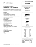
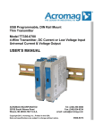
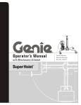
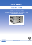
MAINTENANCE
1
PERIODIC MAINTENANCE CHARTS
Regular maintenance is required for the best performance and safe operation of
your golf car.
2
3
4
Be sure to turn off the main switch and apply the parking brake when you
perform maintenance, unless otherwise specified. If the owner is not familiar
with servicing the machine, death or serious personal injury can result. When in
doubt the work should be done by a Yamaha dealer or other qualified mechanic.
CS - CHECK
CA - CHECK AND ADJUST
R - REPLACE
Remarks
5
PRE-OP
6
7
8
9
10
EVERY
MONTH
Daily
PreOperation
S - SERVICE
Page
Charge
S
S
S
S
S
S
4-3/
8-5
Clean battery tops, check for
tightness of hold-down screws and
terminals
S
S
S
S
S
S
6-2/
8-3
Check brake pedal freeplay and
adjust if necessary
CS
CA
CA
CA
CA
CA
6-4/
8-10
Check steering operation
CS
CS
CS
CS
CS
CS
6-3
Check tire pressure, tread depth,
tire surface for damage
CS
CA
CA
CA
CA
CA
6-2
Check body and chassis for
damage
CS
CS
CS
CS
CS
CS
6-4
Check tightness of all bolts, nuts,
screws and rivets
CS
CS
CS
CS
CS
CS
*
Check reverse alarm operation
CS
CS
CS
CS
CS
CS
6-3
Check electrolyte level
CS
CS
CS
CS
CS
8-3/8-4
Check for loose or broken
connections
CS
CS
CS
CS
CS
Clean/Lube pedal control area
CL
EVERY 6 Check all wire insulation for cracks
MONTHS and/or worn spots
Check shock absorbers for oil leaks
and damaged springs
11
CL - CLEAN AND LUBRICATE L - LUBRICATE
40 rounds 250 rounds 500 rounds 1000 rounds 2000 rounds
250 hrs
500 hrs
125 hrs
20 hours
1000 hrs
1200 mls
2500 mls
600 mls
100 miles
5000 mls
2000 kms 4000 kms
1000 kms
160 kms
8000 kms
(Every
(Every 2
(Every 6
(Every
(Every 4
Year)
years)
months)
Month)
years)
*
—
CS
CS
CS
CS
*
CS
CS
CS
CS
*
* Items without a page number reference should be serviced by a Yamaha dealer or other qualified mechanic. This manual does
not contain these procedures. They are contained in the Service Manual.
8-1
JW9
MAINTENANCE
CS - CHECK
CA - CHECK AND ADJUST
Remarks
EVERY
YEAR
R - REPLACE
Daily
PreOperation
S - SERVICE
CL - CLEAN AND LUBRICATE L - LUBRICATE
40 rounds 250 rounds 500 rounds 1000 rounds 2000 rounds
250 hrs
500 hrs
125 hrs
20 hours
1000 hrs
1200 mls
2500 mls
600 mls
100 miles
5000 mls
2000 kms 4000 kms
1000 kms
160 kms
8000 kms
(Every
(Every 2
(Every 6
(Every
(Every 4
Year)
years)
months)
Month)
years)
Perform a discharge test
S
S
S
*
Apply Terminal protectant
S
S
S
—
Check rear axle bearing play
for roughness or freeplay
CS
CS
CS
*
Check steering knuckle
bushing freeplay / Adjust
wheel alignment
CA
CA
CA
*
Check wheel nut tightness, front
wheel bearing play
CS
CS
CS
*
Check transaxle oil level and
inspect for leakage
CS
CS
CS
8-9
Check pedal stop operation and
adjust if necessary
CA
CA
CA
*
EVERY 2
YEARS
Replace transaxle oil
EVERY 4
YEARS
Inspect internal wet brake and
replace pads if necessary
R
1
Page
2
3
4
5
*
CA
*
* Items without a page number reference should be serviced by a Yamaha dealer or other qualified mechanic. This manual does
6
not contain these procedures. They are contained in the Service Manual.
7
8
9
10
11
JW9
8-2
MAINTENANCE
Battery Care
1
Battery electrolyte is poisonous
and dangerous, causing severe
burns, etc. It contains sulfuric acid.
Avoid contact with skin, eyes, or
clothing.
Antidote:
EXTERNAL: Flush with water.
INTERNAL: Drink large quantities of
water or milk. Follow with milk of
magnesia, beaten egg, or vegetable
oil. Call physician immediately.
EYES: Flush with water for 15
minutes and get prompt medical
attention.
Batteries produce explosive gases.
Keep sparks, flame, cigarettes, etc.,
away.
Ventilate when charging or using in
enclosed space. Always shield eyes
when working near batteries.
KEEP OUT OF REACH OF
CHILDREN.
2
3
4
5
6
7
8
Six 8-volt deep cycle batteries
provide power for your electric golf
car and must be properly maintained
and recharged for maximum
performance and service life.
To maintain your batteries:
1. Clean the tops of the batteries
with a solution of baking soda
and water, as necessary, to
remove corrosion.
9
10
11
NOTICE
Do not allow cleaning solution to
enter battery cells. Serious battery
damage can result.
2. Check the fluid level before and
after charging.
8-3
JW9
MAINTENANCE
Fill Well
Electrolyte 1/8” Below
Bottom of Fill Well
Max. Level charged battery
Electrolyte
1/8”
(3 mm)
l
Before charging: only add distilled
water if fluid is below the top of the
plates, and then add just enough to
cover plates.
l
After charging: open the vent caps
and look inside the fill wells. Add
distilled water until the electrolyte
level is 3 mm (1/8") below the
bottom of the fill well. A piece of
rubber can be used safely as a
dipstick to help determine this level.
Clean, replace and tighten all vent
caps.
Max. Level discharged battery
NOTICE
3. Using a hydrometer, check the
specific gravity of the battery fluid
in each cell against the readings
on the chart below. Consult a
Yamaha dealer if any low readings
are found, or if readings vary more
than one point between cells.
Temperature
°C
°F
Satisfactory Uncorrected
Hydrometer Reading
48.9
120
1.244
43.3
110
1.248
37.8
100
1.252
3
4
32.2
90
1.256
26.7
80
1.260
21.1
70
1.264
15.6
60
1.268
10.0
50
1.272
4.4
40
1.276
-1.1
30
1.280
6
7
8
9
10
11
Y-936a
JW9
2
5
Normal tap water contains
minerals which are harmful to a
battery; therefore, refill only with
distilled water.
Y-937c
1
8-4
MAINTENANCE
Battery Charging
1
Read and understand the owner’s
manual provided with your golf
car’s battery charger before
charging batteries. Death or
serious personal injury can result
from failing to comply with the
safety and warning instructions
affixed to the golf car or utility
vehicle.
2
3
4
Explosive hydrogen gas is
produced while batteries are
being charged. Only charge
batteries in well ventilated areas
(a minimum of five air changes
per hour is recommended). Death
or serious personal injury can
result from failing to comply with
the safety and warning
instructions affixed to the golf car
or utility vehicle.
5
6
7
8
OFF
REV
FWD
ON
9
To charge the batteries in your
golf car, follow the instructions
contained in your battery charger’s
owner’s manual. The following is a
summary of the charging steps.
1. Turn main switch key to “OFF”
position.
10
Y-912
NOTICE
Always put the tow switch in the
“TOW” position before charging
battery or damage to the electrical
system may result.
11
2. Lift up the seat and move the tow
switch to the TOW position.
8-5
JW9
MAINTENANCE
NOTICE
Use only battery chargers that are
rated for use with 48-volt Yamaha
Golf Cars. Serious battery damage
can result. Thoroughly read and
understand the user manual
supplied with your 48-volt charger.
3. With the charger properly
connected and grounded (see
charger’s owner’s manual), insert
the DC output into the golf car
receptacle.
Y-669c
POWER ON
A
ERROR1
B
ERROR2
C
CHARGING
90%
CHARGED
D
E
Do not disconnect the DC output
cord from the battery receptacle
when the charger is on or an arc
could occur that may cause an
explosion. Death or serious
personal injury can result from
failing to comply with the safety
and warning instructions affixed
to the golf car or utility vehicle.
å
∫
ç
∂
fl
Power ON Light (Red)
Error Light 1 (Red)
Error Light 2 (Red)
Charging Light (Yellow)
Charged Light (Green)
4. When the charger is plugged into
the AC power, the Power ON
Light illuminates continuously.
5. If Error 1 or Error 2 light is
blinking, there is a problem with
the batteries or the charger.
Contact your Yamaha Dealer.
Y-1559
JW9
6. During normal charging, the
Charging Light blinks or
continually illuminates.
7. The charger turns off
automatically when the batteries
reach full charge.
8-6
1
2
3
4
5
6
7
8
9
10
11
MAINTENANCE
8. After the charger has turned off,
disconnect the DC output plug
from the golf car receptacle by
grasping the plug body and
pulling the plug straight out of
the receptacle.
1
2
Battery Installation
3
When working with batteries, do
not put wrenches or other metal
objects across the battery
terminals. An arc can occur
causing an explosion or fire at the
battery. Death or serious personal
injury can result from failing to
comply with the safety and warning
instructions affixed to the golf car
or utility vehicle.
4
5
6
C
B
A
Y-751D
7
1. Install the battery holddown
plates and torque to 7-9 Nm, 0.70.9 m•kg (62-80 in•lb) as shown.
å Forward
∫ Battery
ç Battery holddown plate
8
2. Connect the wire leads and
torque to 9-10 Nm, 0.9-1.0 m•kg
(80-89 in•lb) as shown.
9
10
Y-672h
11
8-7
When installing batteries:
l Carefully place battery cables
and hold-downs making sure
that cables do not lay across
vent caps.
l Always remove the negative (–)
cable to the motor controller
first, and install it last. A spark
can occur causing an explosion
or fire at the battery. Death or
serious personal injury can
result from failing to comply
with the safety and warning
instructions affixed to the golf
car or utility vehicle.
JW9
MAINTENANCE
NOTICE
1
Do not overtighten the battery
holddown nuts. Excessive force
will damage the battery casing.
2
Fuse Replacement
3
B
A
Y-523a
Be sure to use the specified fuse.
Using a wrong fuse can cause
electrical system damage and
create a fire hazard. Death or
serious personal injury can result
from failing to comply with the
safety and warning instructions
affixed to the golf car or utility
vehicle.
4
5
6
Fuse Type:
3 Amp, Blade Style
NOTICE
7
When replacing a fuse be sure
the main switch is turned off to
prevent accidental shortcircuiting and electrical system
damage.
8
1. Locate the in-line fuse holder on
the main wire harness adjacent
to the tow switch.
2. Pull fuse holder cover off.
9
10
3. Pull fuse out, inspect and replace
if necessary.
11
å Fuse holder
∫ Fuse
JW9
8-8
MAINTENANCE
Transaxle Oil
1
To check transaxle oil level:
1. Place the golf car on a flat, level
surface.
2
3
1
3
2. Remove seven plastic rivets 1
and two bolts 2, and remove the
bag holder insert 3.
3. Place an oil pan under the
transaxle case.
2
4. Clean area around servicing plug 4.
4
5
Y-1994
5. Using an 8 mm hex wrench,
remove transaxle oil servicing
plug located on the rear of the
transaxle case.
6. Transaxle oil should be at the top
of the oil servicing hole or just
beginning to run out of hole.
6
NOTICE
4
Do not allow foreign material to
enter transaxle. Serious transaxle
damage can result.
7
8
Y-1214
9
7. If needed, add Yamalube Friction
Modified Shaft Drive Gear Oil
until it is at the top of the plug
hole or just beginning to run out
of servicing hole.
TIP
The YDRE Golf Car is equipped with
an internal wet brake. Use of oil other
than Yamalube Friction Modified
Shaft Drive Gear Oil will cause brake
noise.
10
11
8. Install the transaxle servicing
plug and tighten to 14-19 Nm,
1.4-1.9 m•kg (120-168 in•lb).
9. Install the bag holder insert
3 and secure with two bolts 2
and seven plastic rivets 1.
8-9
JW9
MAINTENANCE
TIP
For transaxle oil replacement,
consult a Yamaha dealer or other
qualified mechanic.
1
2
NOTICE
Before performing wheel or brake
maintenance, verify that the main
switch is in the “OFF” position.
Serious transaxle damage can
result.
Y-57
3
4
Wheel Replacement
To remove and install a wheel on
your golf car:
1. With the wheels blocked to
prevent the golf car from moving,
loosen the wheel nuts.
2. Elevate the golf car with a jack
and remove the wheel nuts and
the wheel.
3. Reverse the removal steps when
installing the wheel.
Wheel nut tightening torque:
80 Nm, 8.0 m.kg (58 ft.lb)
5
6
7
8
Brake Adjustment
The brakes on your golf car are
self-adjusting.
Before you operate the car, press
down on the brake pedal several
times to make sure the brakes are
functioning properly.
9
10
11
Consult your Yamaha dealer before
using your golf car if you suspect
brake problems. Death or serious
personal injury can result from
failing to comply with the safety
and warning instructions affixed to
the golf car or utility vehicle.
JW9
8-10
MAINTENANCE
Brake Pedal Free Play
Adjustment
1
NOTICE
2
Before adjusting brake pedal free
play, pump the brake pedal several
times to self-adjust the brakes.
3
To adjust the brake pedal free play:
1. Remove the floor mat and
service lid from the floor of the
golf car.
4
5
6
Y-61c
7
a
8
8
9
10
11
12
13
14
15
16
17
2. Check the brake pedal free play
by pressing against the pedal
with two fingers (using light
force) and measuring the
distance the pedal travels before
resistance is felt.
18
Brake pedal free play Å:
45-50 mm (1.77-1.96 in.)
7
9
Y-62b
10
A
B
11
3. If the free play distance needs
adjusting, loosen the lock nut å
(under rubber bushing) and turn
the adjusting nut ∫ in or out
until free play specification is
met. Then tighten the lock nut in
place.
NOTICE
Y-909D
8-11
Do not over-tighten the brake
cables. Over-tightening will
increase brake wear and affect
overall performance of car.
Premature brake wear can result.
JW9