1
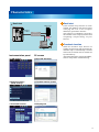
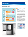
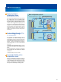
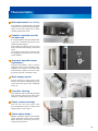
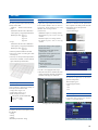
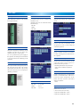
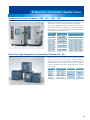
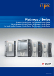
Platinous J Series
Low temperature (& humidity) chamber
Temperature & humidity chamber
CAT.NO.-E11110
The Platinous J Series
– the next generation global standard
Our renowned Platinous chambers have evolved into a new model
that achieves great reductions in power consumption.
With an abundant choice of options and improvements for an “on-demand” supply,
the Platinous J Series is quickly and economically modeled according to your needs.
For this remodeling, we paid particular attention to the high reliability and performance
carried out through this particular chamber, and polished it into the new J Series.
We have also been looking ahead to the demands of the times and worked to develop a series
that incorporates those demands with the same ESPEC style and the essence of
the Platinous Series you have come to expect.
Furthermore, the Platinous J Series is equipped with the new N-Instrumentation that makes
connections with network communications possible.
Now a half-century from the first-generation Platinous Series, these are the chambers that will
set the global standard for the next generation and make ESPEC rhymes with “best technology”.
Type 1
1
Type 2
Type 3
Type 4
* Equipped with options.
2
Characteristics
Networking communications and USB data transfer for
optimum test operations
Network communication and
USB memory support
An Ethernet port on the chamber side
allows remote connection to the chamber
for monitoring and control. (Wi-Fi)
Data management
Chamber operation log data can be
exported to a PC using either the Ethernet
connection or a USB memory.
Data can be opened as a list or graph thanks
to a dedicated viewer or spreadsheet, and
can be used to check historical data.
Remote monitoring
Program pattern edit and copy
Program patterns can be created on the
PC and then transferred to the chamber
either via the intranet or USB. The USB
is also useful to transfer programs from
one chamber to another.
Remote monitoring and
control
You can operate the chamber from a remote
PC to monitor the test status, change test
conditions, and start or stop the chamber
operation. A simple setting of the IP
address on the controller and your PC, no
software or drivers are necessary.
USB port
Function compatibility
Functions
Data management
Program pattern edit/copy
Remote monitor and control
Email alert
Traceback function
3
Ethernet port
Ethernet
USB memory
Characteristics
Email alert
Email alert
Mail server
Ethernet
or Wi-Fi
Intranet
(company LAN)
Notification
If the chamber stops because of some
trouble, the chamber will send an email
notifying the error to the recipient
address(es) specified in advance.
This function is available by connecting
the chamber to the company intranet and
completing a simple setting via your
browser.
Platinous J
Traceback function
PC
Instrumentation panel
PC screen
● LAN settings
● Run/stop operation
● External memory
● Chamber monitor (graph)
● Traceback function
● Edit program
(USB) settings
When the chamber stops because of
trouble, the operation state just before the
chamber stops is automatically recorded
and saved. Saved data can be transferred
by USB memory.
Attach this data file to an email to ESPEC,
and we will perform troubleshooting.
4
Characteristics
High-speed processing N-Instrumentation features improved operability
and legibility
Tabbed user interface
Controller’s new layout includes tabs at
the bottom of the screen to easily activate
any section.
Calculating and processing performances
have been improved, and the screen layout
optimized.
Register test patterns
Up to 40 patterns for program operation
and 3 patterns for constant operation can
be registered.
Sampling function
The temperature and humidity measurement
targets, and measurement intervals can
be set.
The trend graph with set conditions and
data are saved in the controller memory.
These data can then be transferred on a
USB memory.
Information screen
● Trend graph
● Operation mode
● Information
5
● Program details settings
T he infor mation section displays
information on the chamber status, such
as defrosting, or humidifying tray water
auto refill.
Messages displayed according to operating
timer inform you of the humidifier
maintenance checks, condenser filter or
strainer checks.
It is also possible to register and use
additional notification items.
Characteristics
N-Instrumentation
Operating mode
Constant operation, program operation, remote operation, stop
Temperature & humidity control
function
Control system: Temperature input:
Humidity input:
Input functions: Adjustment function:
Setting resolution
• Constant setup
Setting range: 3 types
Setting range and resolution:
Temperature: (lowest attainable temp. −5°C) to +105.0°C, 0.1°C unit
Humidity: 0% rh to 100% rh, 1% rh unit
• Program setup
Setting range: 40 programs (99 steps per program)
Setting range and resolution:
Temperature: (lowest attainable temp. −5°C) to +105.0°C, 0.1°C unit
Humidity: 0% rh to 100% rh, 1% rh unit
Time: 0 hours 1 minute to 9999 hours 59 minutes, 1 minute unit
Language
English, Japanese (switch without restarting)
PID control (sample temperature control support),
energy-saving refrigeration capacity automatic control
Test chamber temperature (Thermocouple type T)
Test chamber wet-and-dry-bulb temperature input system
(Thermocouple type T)
100 ms high-speed sampling, wire break detection
Temperature offset setting
• Basic functions
Operation, eco operation display, alarm, information,
accessory (integrating hour meter, water discharge setting), help,
test area monitor (temperature & humidity, external output, trend graph)
Auxiliary functions
• Management & setup functions
Timer preset (start timer, stop timer, quick timer), sampling setting,
protect, alarm history display, version display,
hour meter with reset, notification
• Maintenance functions
Chamber operation settings (power outage recovery setting, backup operation setting, operation
when door open setting), temperature attainment condition settings,
time signal name registration, chamber detailed settings (refrigerator control mode setting, wick
continuous water supply setting, humidifier pan water auto replacement function, external alarm
output setting, humidifier delay setting), user password, date/time setting
External memory functions
• Interface: USB 2.0 standard compliant (connector A-type)
• Supported functions
Write log, read/write program, write traceback
Web function
• Interface: Ethernet (100base-TX)
• Server functions
Remote monitor, remote setup (constant, program), remote operation,
alarm mail notification
6
Characteristics
Energy savings and high performance achieved thanks to
the refrigeration system
• Temperature control
Operating conditions
0.50
1.00
1.50
PL-3
+60°C
2.00
2.50
Energy
savings rate
PR-3
66%
max.
PU-3
PL-3
+20°C
PR-3
PU-3
• Temperature & humidity control
Operating conditions
+85°C /
85%rh
+60°C /
60%rh
+20°C /
40%rh
0.50
1.00
1.50
Power consumption (kWh)
2.00
2.50
PL-3
Energy
savings rate
PR-3
70%
max.
PL-3
PR-3
PL-3
PR-3
Power consumption comparison when equipped
with the DC inverter energy saving system
J Series
K Series (PL - AC inverter spec.)
Operating conditions
0
PL-3
-20
PU-3
-10
0.50
1.00
Power consumption (kWh)
1.50
2.00
2.50
Energy
savings rate
48%
max
The J Series switches between large and
small refrigerators, depending on the
chamber capacity and the temperature and
humidity range; it also handles precisely
various heat loads by using a multicompressor system that manage a main
and a sub-circuit.
From the first Platinous Series sold in 1961,
we have been strongly committed to response
and accuracy in the control of temperature
and humidity (air-conditioning system), by
adopting our own unique systems.
In this series, we made further improvements
of our control system by focusing on energy
savings more than ever.
One of these enhanced features is the PID
control of refrigeration capacity. The Smart
Refrigerator & Dehumidifier System can
control minutely both heating and cooling
at minimal levels, thanks to the new
N-instrumentation embedded in the
chamber. PID control applies to both main
and sub refrigeration circuits.
Energy savings principle diagram
Heater output
J Series
K Series
Power consumption (kWh)
Smart Refrigerator and
Dehumidifier System with PID
control (Patent pending)
Test area
stabilization
point
Refrigeration
output
Power consumption comparison (example)
K Series
Heating/
humidifying
Cooling/
dehumidifying
K Series (PL - AC inverter spec.)
7
Chamber equipped with shelves (option)
J Series
Heating PID control
N-Instrumentation
Refrigeration
PID control
N-Instrumentation
Characteristics
On chambers equipped with the 400 W
refrigerator, the Smart Refrigerator &
Dehumidifier System controls the operation
when stable at constant ranges above 50°C
/40%rh, after the chamber activated the
sub refrigerator to run at minimum
capacity.
Chambers using this double energy saving
control can run with the best energy-saving
rates.
For example, the PL−3J power consumption
can be cut by 70% max. under 60°C /60%rh
conditions.
(Compared to previous model)
Accumulator
Expansion
mechanism
Solenoid valve
Expansion
mechanism
Compressor
1.5 kW
(Type 4:
3 kW)
Condenser
Bypass
circuit
Main refrigeration circuit
Heat
exchanger
Sub refrigeration circuit
Compressor
400W
Condenser
PL−2/3/4, PU−2/3/4
Test
area
Solenoid
valve
Bypass
circuit
A sub refrigeration circuit for
further energy savings
Electronic expansion valve
Intermediate
injection circuit
The electronic expansion valve located on
the cooling side, has an extended water
flow control rate (0 to 100%), while the
Smart Refrigerator & Dehumidifier System
controls the refrigeration capacity to its
minimum. Consequently, while creating
a highly accurate temperature and humidity
environment, the refrigeration circuit
suppresses heater output and reduces
power consumption of both refrigerator
and heater.
New refrigeration circuit
Evaporator (cooler)
(Main refrigeration circuit)
Evaporator (cooler)
Newly developed
refrigeration circuit
Heat
exchanger
Increased reliability of the
refrigeration circuit
We have installed an injection circuit for
compressor cooling. A heater exchanger
is also installed in the refrigeration system
and the compressor is protected from
refrigerant accidentally flooding back.
8
Characteristics
Optimum use of your chamber
Select the combination of your features
almost from scratch: combination of doors,
viewing windows, hand-in ports in
accordance with your needs.
We offer several configurations including
water- or air-cooled refrigeration system,
expanded temperature specification (to
150 or 180°C), etc. from basics, to deliver
the customer its very own chamber.
Wide-view door (with hand-in ports)
Viewing window (Type 4)
Quick lead-time for extended
range of options
Over 60 options are available for selection,
and we ar ranged process so that
compatibility to any model of the Series
can be done smoothly according to your
needs.
Even when selecting a number of options,
we can deliver a customized product in
short time.
25 retrofit options are also available as
option package (easy installation).
Right-side cable port
Right-side cable port
(Patent pending)
Until now, Platinous chamber were
equipped with a control panel and
machinery compartment, preventing
access of the test area on the right side.
In the J Series, it is now possible to add a
cable port on the right side of the chamber
(option).
Right side now includes a customer space,
where we can add several options, such
as the right side cable port, but also
decrease protrusions, according to the
customer requests.
Migration Evaluation System Connection (example)
Combination with ESPEC
evaluation systems
Even more accurate ion migration
evaluations can be performed by connecting
a Platinous J Series to our AMI System
(sold separately).
When the right side cable port is equipped,
free access on both sides of the chamber
is available, and it is easier to install
multiple units.
9
Characteristics
Wick replacement (Patent pending)
The difficulty in replacing the wet-bulb
wick has been improved by changing the
shape of the wick's plug part to allow
smooth replacement work.
Chamber restricted use with
the door lock
It is now possible to lock the chamber door
to prevent accidental operation of the
chamber during testing.
The handle part design has also been
improved so the door closing is easier and
safer.
As an option, a power key switch can also
be equipped to control the start and stop
of the chamber.
Wick inside chamber
Automatic humidifier water
replacement
Stagnant humidifier water contains
impurities and is a cause of trouble, so the
chamber now features a function that
automatically replaces the water at the
period set from the controller screen.
Door handle lock
Power key switch
Water tank
Additional water supply tank (option)
Water supply system
Several options to supply water to the
chamber are offered, including direct tap
water connection, pure water, additional
tanks, etc.
Easy filter cleaning
The condenser filter can be easily attached
and removed from the left side of the
chamber to make cleaning even easier.
Reuse, resource savings
The test area size is the same as the
previous Platinous Series so shelves and
shelf brackets can be reused.
Global safety design
ESPEC chambers support international
safety standards based on IEC−60204,
EMC directives, machinery directives,
and pressure directives.
Condenser filter
10
PR
−20 to +100°C · 20 to 98% rh
TEMPERATURE & HUMIDITY CHAMBER
Model
PR−1J
System
PR−2J
Performance*1
Temp. & humidity fluctuation
±0.3°C/±2.5% rh
Temp. & humidity gradient
3.0°C/10% rh
Temperature & humidity variation
in space
1.5°C/5% rh
Temperature range: −8 to +88°C
Heat up rate: 3.0°C/min.
Pull down rate: 2.0°C/min.
Temperature rate of change
Temperature extremes
achievement time
Heat up time: from +20 to +100°C 30 min.
Pull down time: from +20 to −20°C 40 min.
Exterior material
Stainless steel plate: 18 Cr stainless steel plate, hairline finish
Test area material
Stainless steel plate: 18−8 Cr−Ni stainless steel plate, 2B polish
Heater
Nichrome strip wire heater
Humidifier
18-12−2.5 Cr−Ni−Mo stainless steel sheathed heater (surface evaporating system)
Cooler (dehumidifier)
Plate fin cooler
Air circulator
Water
supply
Cross flow fan
Supply system
Water tank
16 L
Rotary compressor (R404A)
Refrigerator capacity
0.65 kW
Expansion mechanism
Dimensions*2
1.2 kW
Electronic expansion valve
120
225
Chamber total load resistance (kg)
408
800
100
Inside dimensions
(W x H x D mm)
500 x 600 x 400
500 x 750 x 600
600 x 850 x 800
1000 x 1000 x 800
Outside dimensions
(W x H x D mm)
910 x 1440 x 873
910 x 1590 x 1073
1010 x 1690 x 1273
1410 x 1840 (1970)
x 1273
260
305
365
480
Weight (kg)
Allowable ambient conditions
Utility requirements
32 L
Mechanical type single-stage compression cooling
Compressor
Capacity (L)
Sirocco fan
Pump out system
System
Refrigeration
unit
PR−4J
−20 to +100°C/20 to 98% rh
(lowest attainable temperature in an ambient temperature of 0 to +30°C)
Temp. & humidity range
Construction
PR−3J
Balanced Temperature and Humidity Control system (BTHC system)
Power
supply
0 to +40°C/up to 75% rh
200V AC 3ø 50/60 Hz
18.5 A
20.0 A
22.0 A
34.0 A
220V AC 3ø 60 Hz
17.5 A
20.0 A
20.5 A
31.5 A
380V AC 3ø 50 Hz
8.5 A
10.0 A
10.0 A
20.5 A
400V AC 3ø 50 Hz
8.0 A
9.5 A
9.5 A
19.5 A
Allowable heat load
1100 W
1250 W
*1 Temperature and humidity chamber based on IEC60068−3−6:2001 (JIS C60068−3−6:2008 and JTM K09:2009), for ambient temperature +23°C, relative humidity
65±20% rh, rated voltage, no specimen.
*2 Excluding protrusions. Dimensions indicated in ( ) include protrusions.
11
PL
−40 to +100°C · 20 to 98% rh
LOW TEMPERATURE AND HUMIDITY CHAMBER
Model
PL−1J
System
PL−2J
Performance*1
Temp. & humidity fluctuation
±0.3°C/±2.5% rh
Temp. & humidity gradient
3.0°C/10% rh
Temperature & humidity variation
in space
1.5°C/5% rh
Temperature range: −26 to +86°C
Heat up rate: 3.0°C/min.
Pull down rate: 2.0°C/min.
Temperature rate of change
Temperature extremes
achievement time
Heat up time: from +20 to +100°C 30 min.
Pull down time: from +20 to −40°C 50 min.
Exterior material
Stainless steel plate: 18 Cr stainless steel plate, hairline finish
Test area material
Stainless steel plate: 18−8 Cr−Ni stainless steel plate, 2B polish
Heater
Nichrome strip wire heater
Humidifier
Cooler (dehumidifier)
18−12−2.5 Cr−Ni−Mo stainless steel sheathed heater (surface evaporating system)
Plate fin cooler
Air circulator
Water
supply
Plate fin cooler, stainless steel tube cooler
Cross flow fan
Supply system
Compressor
Refrigerator capacity
Expansion mechanism
Capacity (L)
16 L
32 L
Mechanical type single-stage compression cooling
Rotary compressor
(R404A)
Rotary compressor (R404A)
Reciprocating compressor (R404A)
Scroll compressor
(R404A)
Reciprocating
compressor (R404A)
1.2 kW
1.5 kW + 0.4 kW
3.0 kW + 0.4 kW
Electronic expansion
valve
120
Electronic expansion valve, capillary tube
225
Dimensions*2
Chamber total load resistance (kg)
408
800
100
Inside dimensions
(W x H x D mm)
500 x 600 x 400
500 x 750 x 600
600 x 850 x 800
1000 x 1000 x 800
Outside dimensions
(W x H x D mm)
910 x 1440 x 873
910 x 1590 x 1073
1010 x 1690 x 1273
1410 x 1840 (1970) x
1273
270
340
420
610
Weight (kg)
Allowable ambient conditions
Utility requirements
Sirocco fan
Pump out system
Water tank
System
Refrigeration
unit
PL−4J
−40 to +100°C/20 to 98% rh
(lowest attainable temperature in an ambient temperature of 0 to +30°C)
Temp. & humidity range
Construction
PL−3J
Balanced Temperature and Humidity Control system (BTHC system)
Power
supply
0 to +40°C/up to 75% rh
200V AC 3ø 50/60 Hz
22.5 A
22.5 A
23.0 A
36.0 A
220V AC 3ø 60 Hz
21.0 A
22.0 A
22.0 A
34.0 A
380V AC 3ø 50 Hz
10.0 A
11.0 A
11.0 A
22.0 A
400V AC 3ø 50 Hz
9.4 A
10.4 A
10.4 A
21.0 A
850 W
1400 W
1500 W
2850 W
Allowable heat load
*1 Temperature and humidity chamber based on IEC60068−3−6:2001 (JIS C60068−3−6:2008 and JTM K09:2009), for ambient temperature +23°C, relative humidity
65±20% rh, rated voltage, no specimen.
*2 Excluding protrusions. Dimensions indicated in ( ) include protrusions.
12
PU
−40 to +100°C
LOW TEMPERATURE CHAMBER
Model
PU−1J
PU−2J
System
PU−3J
Temperature range
−40 to +100°C (lowest attainable temperature in an ambient temperature of 0 to +30°C)
Performance*1
Temperature fluctuation
±0.3°C
Temperature gradient
3.0°C
Temperature variation in space
1.5°C
Temperature range: −26 to +86°C
Heat up rate: 3.0°C/min.
Pull down rate: 2.0°C/min.
Temperature rate of change
Temperature extremes
achievement time
Heat up time: from +20 to +100°C 30 min.
Pull down time: from +20 to −40°C 50 min.
Exterior material
Stainless steel plate: 18 Cr stainless steel plate, hairline finish
Test area material
Stainless steel plate: 18−8 Cr−Ni stainless steel plate, 2B polish
Heater
Nichrome strip wire heater
Construction
Humidifier
Cooler
18-12−2.5 Cr−Ni−Mo stainless steel sheathed heater (surface evaporating system)
Plate fin cooler
Air circulator
Compressor
Refrigerator capacity
Expansion mechanism
Capacity (L)
Plate fin cooler, stainless steel tube cooler
Cross flow fan
System
Refrigeration
unit
Dimensions*2
Sirocco fan
Mechanical type single-stage compression cooling
Rotary compressor
(R404A)
Rotary compressor (R404A)
Reciprocating compressor (R404A)
Scroll compressor
(R404A)
Reciprocating compressor
(R404A)
1.2 kW
1.5 kW + 0.4 kW
3.0 kW + 0.4 kW
Electronic expansion
valve
120
Electronic expansion valve, capillary tube
225
Chamber total load resistance (kg)
408
800
100
Inside dimensions
(W x H x D mm)
500 x 600 x 400
500 x 750 x 600
600 x 850 x 800
1000 x 1000 x 800
Outside dimensions
(W x H x D mm)
910 x 1440 x 873
910 x 1590 x 1073
1010 x 1690 x 1273
1410 x 1840 (1970)
x 1273
260
330
410
600
Weight (kg)
Allowable ambient conditions
Utility requirements
PU−4J
Balanced Temperature Control system (BTC system)
Power
supply
0 to +40°C/up to 75% rh
200V AC 3ø 50/60 Hz
14.5 A
15.0 A
15.0 A
28.0 A
220V AC 3ø 60 Hz
14.0 A
14.0 A
14.0 A
26.5 A
380V AC 3ø 50 Hz
9.0 A
10.5 A
10.5 A
13.5 A
400V AC 3ø 50 Hz
8.5 A
10.0 A
10.0 A
12.8 A
850 W
1400 W
1500 W
2850 W
Allowable heat load
*1 Temperature chamber based on IEC60068−3−5:2001 (JIS C60068−3−5:2006 and JTM K07:2007), for ambient temperature +23°C, relative humidity 65±20% rh,
rated voltage, no specimen.
*2 Excluding protrusions. Dimensions indicated in ( ) include protrusions.
13
TEMPERATURE & HUMIDITY CONTROL RANGE
SAFETY DEVICES
• Control circuit overcurrent protection
PR · PL
• Glass tube fuse for control circuit short-circuit protection
(At ambient temperature +23°C with no load)
100
• Air circulator short-circuit protection
98
90
• Electrical compartment door switch
80
• Absolute upper/lower temperature limit alarm
70
(with built-in temperature/humidity controller)
Relative 60
humidity 50
% rh
40
• Chamber door switch
• Specimen power supply control terminal
30
• System error (error/alarm)
20
• Room temperature compensation burnout detection
10
0
10
20
30
15
40
50
60
70
80
90
circuit
100
85
Temperature °C
• Dry bulb temperature burnout detection circuit
• Wet bulb temperature burnout detection circuit
* Continuous humidity operation at +40°C or lower because of frost on the cooler.
• Reverse prevention relay
• Temperature switch for air circulator
• Thermal fuse
ACCESSORIES
• Temperature switch for condenser fan
• Condenser fan short-circuit protection
· PL connection port
• Power
PRcable
(Unloaded
at ambient
temperature +23°C)
• Drain
hose (approx.
1 m)
• Overheat protector
100
• Condenser
filter (x1)
• 98
Heater overcurrent protection
• Dew tray (x1)
80
• Refrigerator 1 Temperature sensor burnout detection circuit
90
• Refrigerator-1 Circuit temperature range over
Relative humidity % rh
• Cable port70(I.D. ø50 mm on the left-side x1)
• Chamber lamp (Bulb-type fluorescent light x1)
• Refrigerator-1 High-pressure pressure switch
• Casters (Free
rolling type with leveling feet x4)
40
• Refrigerator-1 Low-pressure pressure switch (Type 4 only)
• Time
60
50
30 terminal
signal
20
• Refrigerator-1 Discharge pipe temperature switch
(2 contacts)
• Refrigerator-1 Discharge pipe out of temperature range
• Specimen10power supply control terminal (1)
• LAN terminal
0 (x1)
10
20
15
30
40
50
60
• Refrigerator-1 Compressor surface out of temperature range
70
Temperature °C
80
90
85
INCLUDED ITEMS
100
• Refrigerator-1 Frost detection circuit (error/alarm)
• Refrigerator-1 Short-circuit protection
* Restrictions on continuous humidity operation at +40°C or lower because of frost on the cooler.
• Refrigerator-1
• Cable port rubber plug (ø50 mm)·································· 1
• Door key········································································· 2
• Glass fuse (7A)····························································· 2
• Breaker handle stopper················································· 1
• Wet bulb wicks (except PU)·····································1 box
• User's Manual (DVD, booklet)··································1 set
Overcurrent protection
• Refrigerator-3 High-pressure pressure switch
(Models PL, PU−2 to 4 only)
• Refrigerator-3 Short-circuit protection
(Models PL, PU−2 to 4 only)
• Refrigerator-3 Overcurrent protection
(Models PL, PU−2 to 4 only)
• Humidifier overcurrent protection (except PU)
• Humidifier dry heat protector (except PU)
MODEL (J Series)
P − J
• Humidifier water level detection (except PU)
• Temperature upper limit deviation alarm
(with built-in temperature/humidity controller)
Size / Interior volume
1 : 120 L
2 : 225 L
3 : 408 L
4 : 800 L
Series
R −20 to +100°C / 20 to 98%rh
L −40 to +100°C / 20 to 98%rh
U −40 to +100°C
• Absolute upper/lower humidity limit alarm (with built-in
temperature/humidity controller)(except PU)
• Water tank drought switch (except PU)
• Water tank low-level switch (except PU)
• Dry wick detection (except PU)
14
DOOR (SELECTION)
Wide view door
Door with viewing window
Door without viewing window
*The photo shows optional hand-in ports.
Effective view (mm)
Type 1 to 3: W180 x H260
Type 4:
W295 x H380
Hand-in ports
Type 2 & 3: 2 (a pair)
Type 4: 2 (a pair) or 4 (two pairs)
Effective view (mm)
Type 2:
W470 x H720
Type 3:
W570 x H820
Type 4:
W970 x H970
Hand-in ports
Type 3 & 4: 2 (a pair)
OPTIONS
Additional cable port (with rubber plug)
Cable port rubber plug
Shelf/shelf bracket
Provided in addition/replacement of the
standard cable port (left-side).
• ø25 mm (left-side or ceiling only)
• ø50 mm
• ø100 mm
• Flat cable port
(left side or ceiling only)
* A cable port cannot be installed on the
right side of the Type 1
Prevents air leakage from the cable port.
• ø25 mm
• ø50 mm
• ø100 mm
• For the flat cable port
• Spiral-wrapped plug
• Stainless steel shelf/shelf brackets
• Resin-coated shelf/shelf brackets
ø50 mm
Left-side (chamber interior)
15
Right-side
Spiral-wrapped type
Type 1: W350 x D467 mm
Type 2: W550 x D467 mm
Type 3: W750 x D567 mm
Type 4: W750 x D967 mm
OPTIONS
Specimen basket
Inner glass door
Specimen temperature control
For small specimens that cannot be placed
directly on the shelf.
Material: Stainless steel (4 mesh)
• Small
Dimensions: W350 x H35 x D270 mm
Load capacity: 3 kg (equally distributed load)
Baskets per shelf: Type 1: 1
Type 2: 2
Type 3: 4
Type 4: 6
• Large
Dimensions: W750 x H35 x D450 mm
Load capacity: 5 kg (equally distributed load)
Baskets per shelf: Type 3: 1
Type 4: 2
* Place the specimen baskets on the shelf.
* D o not use when exceeding the shelf
load capacity.
*T
ests may not satisfy standard performance
if the air flow is blocked, so ensure sufficient
space around the specimen baskets.
A glass door is provided between the test
area and the chamber door to obser ve
speci men s. Select ha nd-i n por t s a nd
chamber door viewing window
(4 selections).
• With hand-in ports, no viewing window
• W it h h a nd -i n p or t s a nd a v iew i ng
window
• No hand-in ports, no viewing window
• N o h a n d -i n p o r t s , w it h a v ie w i n g
window
Sensors are attached to the specimen to
allow exposure tests that provide accurate
temperature stress to the specimen.
• Insulated type
• Non-insulated type
Specification changes when equipped
with the inner door
Temperature extreme heat-up time:
heat-up time + 15 min.
Temperature extreme pull-down time:
pull-down time + 15 min.
Temperature distribution:
±0.5°C spread from each temperature distribution.
Humidity distribution:
±2% rh spread from each humidity distribution.
* The PU is not equipped with a wiper.
* W hen the inner door is attached, the lock
release mechanism normally equipped as
standard on the Type 4 is removed.
Insulated type
Non-insulated type
Thermocouple
At tached to specimen to measure
specimen temperature.
Thermocouple type T
(Copper/Copper-Nickel)
•2m
•4m
•6m
Heavy-duty shelf
Used to hold heavy specimens exceeding the
load capacity of the standard shelf.
• 30 kg (3 max.) Type 1 to 3
• 50 kg (2 max.) Type 1 to 4
• Rack (100 kg/5 level max.)
Load capacity for the standard shelf
Type 1 to 3:10 kg
Type 4:
30 kg
Airflow adjuster
Used when tests requi re low ai r f low
velocity or a constant velocity.
Inner glass door without hand-in ports
Floor reinforcement
To enhance the floor load capacity inside
the chamber.
• 100 kg
• 200 kg
• 300 kg
(Standard specification: 70 kg)
16
OPTIONS
Precision inner chamber
Water-cooled specification
Water supply circuit
Pla ci ng a n alu m i nu m box i n side t he
chamber allow to reduce the air velocity
and maintain the required temperature and
humidity distribution.
Velocity: 0.5 m/sec. or lower
Temperature & humidity fluctuation:
±0.5°C/±2.5% rh
Temperature & humidity distribution:
±0.75°C/±5.0% rh
Outside dimensions (effective cross section):
Type 1 - W400 x H440 x D200 mm
(W335 x H285 mm)
Type 2 - W400 x H590 x D400 mm
(W335 x H435 mm)
Type 3 - W500 x H740 x D600 mm
(W435 x H585 mm)
Type 4 - W900 x H840 x D600 mm
(W835 x H685 mm)
To reduce the effect of exhaust heat, this
option changes the refrigeration system to
a water-cooled condenser.
* Type 3, 4
A water ci rcuit to supply pu re water
continuously to the chamber.
• Water supply coupling (with ion exchanger)
• Pure water coupling (with pressure-reducing valve)
• Water purifier (WS-1) connection port
Tank cart
Cart and tanks for supplying water to the
chamber's fixed tank.
• 10 L x 3
Ion exchanger
Water purifier (reverse osmosis)
Use to continuously supply pure water.
• 100 VAC
• 200 VAC
• 220 VAC
• 230 VAC
Dew drip prevention
Ensures that specimens are not exposed to
water that condenses on the test area
ceiling.
Test area low-silicone
Additional water supply tank
Reduces the production of silicone gas
(siloxane) in the test area.
The additional water supply tan k
complements the water volume of the
st and ard- equipped t an k, to allow
continuous operations for long periods.
• Capacity: 18 L
Brake oil protection
Changes resin par ts (water tan k front
cover, door dew tray, chamber dew tray) to
stainless steel.
* Type 3, 4
Power cable
•2m
•5m
• 10 m
17
* When using the product on the second
floor or a higher floor of a building, we
provide a water leak detection system
(sold separately) to prevent damage
from accidental water leaks.
• Water-cooled specification
• Water purifier
• Water supply coupling
(with ion exchanger)
• Pure water coupling
(with pressure-reducing valve)
• Water purifier (WS−1) connection port
OPTIONS
Chamber dew tray
Temperature (humidity) recorder (digital display)
Temperature (humidity) recorder wiring
Prevents water leaks from the chamber
onto the floor.
• RJ11 6 dots
• RJ12 6 dots
• RJ13 6 dots
• RJ14 6 dots
• RJ21 6 dots
• RJ23 6 dots
• RJ25 6 dots
Preparation of a power cable, temperature
sensor, relative humidity signal and a
grounding wire for additional installation
in the future.
Air circulator removed for shipment
To p r e v e n t d a m a g e s d u e t o h e i g h t
restrictions, the air circulator for type 4
chambers is not mounted on the chamber
during shipment.
(Height with: 1970 mm/ without: 1858 mm)
−50 to +100°C
0 to 100% rh
−50 to +150°C
0 to 100% rh
−100 to +100°C
0 to 100% rh
−100 to +150°C
0 to 100% rh
−50 to +100°C
−100 to +100°C
−100 to +200°C
Recorder output terminal
This terminal outputs the temperature and
relative humidity in the test area.
Paperless recorder
Records the temperature and humidity of
each section such as the temperature inside
the chamber.
• Data saving cycle: 5 sec.
• External recording media:
CF memory card port
(Includes a 256 MB CF card)
USB memory port
• Languages:
Can be switched between English/Japanese
<Temperature type>
• Temperature range:−50 to +100°C
−100 to +100°C
−100 to +200°C
• Number of inputs: Temperature 1
(5 more channels can be turned ON)
<Temperature & humidity type>
• Temperature range:−50 to +100°C
−50 to +150°C
−100 to +100°C
−100 to +150°C
• Humidity range: 0 to 100% rh
• Number of inputs: Temperature 1, Humidity 1
(4 more channels can be turned ON)
Temperature sensor terminal
Ter minal board for dr y-bulb/wet-bulb
sensors in the chamber.
Dual communication logger
In addition to the functions of the paperless
recorder, the dual communication logger
records temperatures inside the chamber
and f rom the temperat u re ( hu m idit y)
controller information, and it allows remote
monitoring and chamber alarm reporting.
Transmitted data:
Operation state,
display temperature (humidity), temperature (humidity) setting, alarm count, alarm number 1/2
• −50 to +100°C
• −100 to +200°C
• −50 to +100°C/0 to 100% rh
• −50 to +150°C/0 to 100% rh
Power meter
Displays the integral power consumption
for the chamber.
18
OPTIONS
Overcool protector
Emergency stop pushbutton
Status indicator light
If the temperature inside the chamber
decreases excessively, the chamber stops
operating to prevent the specimens from
being damaged.
Stops the chamber immediately.
Select light color, bu zzer sou nd, and
lighting or blinking.
• 1 level, light: 1 color, height: 533 mm
• 2 levels, light: 2 colors, height: 575 mm
• 3 levels, light: 3 colors, height: 616 mm
• 4 levels, light: 4 colors, height: 657 mm
Main power switch
Additional overheat protector
Additional preventive measures can be
taken for excessive temperature rise in the
cha mber, i n add it ion to t he st a nd a rd
equipped overheat protector.
The main power switch allows turning the
power ON and OFF from the chamber
front.
Rotating signal light
The rotating signal lights up when an error
occurs.
(Two types of colors are provided, red or
yellow.)
Power key switch
Trouble buzzer
Used to manage/rest r ict the chamber
usage.
Buzzer notification when an error occurs.
External alarm terminal
If the safety device of the chamber is
activated, external alarm terminal will
notify it to a remote point.
Power indicator
The operator can verify if the breaker is
ON or OFF from the chamber front.
Door opening signal output terminal
Capable of controlling an external device
that operates along with door operation
and records the temperature disturbance
history.
19
OPTIONS
Time signal terminal
Interface
Defrost circuit
Adds additional terminals to the standard
time signal terminals.
Com mu n icat ion por ts to con nect t he
chamber to a PC.
(Chamber side ports or connections inside
the machinery)
• RS−485
• GPIB
• RS−232C
Automatically defrosts the refrigeration
circuit.
Frost-free circuit
Prevents frost from accumulating on the
refrigeration circuit to allow long-term
continuous operation.
Temp. & humid. SP attainment output
Evaporator frost check window
When the temperature (humidity) in the
ch a mb e r r e a che s t he s e t va lue s , t he
chamber sends out a contact signal.
Use it to synchronize the power supply to
the specimen, the timing for measurements
or to prevent dew from condensing on the
specimens.
Equips a window inside the test chamber
to allow checking frost accumulation on
the evaporator.
Stainless steel evaporator
Increases the corrosion resistance of the
evaporator when cor rosive gases a re
produced from the specimen.
* Standard performance may not be met
under certain conditions. Inquire for
details.
Time run-out terminal
This option enables turning the power to
the specimen ON or OFF with contact
signal output when the time is up by using
the timer function on the temperature
(humidity) controller.
Sheathed heater with fins
Communication cables
• RS−485
• GPIB
• RS−232C
5, 10, 30 m
2, 4 m
1.5, 3, 6 m
Changes the heater from a stripped wire
heater to a sheathed heater with fins to
lower the su r face temperat u re of the
heater, decrease corrosion, and reduce
defective insulation.
• 200 V
Upper limit modification
Enables tests over 100°C.
(+120°C for the wide view door)
• Upper limit temperature +150°C
• Upper limit temperature +180°C
20
OPTIONS
Instrumentation-interlocking DC power supply
Operation panel cover
Capable of applying voltage to the specimen,
used for bias testing. The DC power supply
unit synchronizes with constant and program
o p e r a t io n s , a n d c a n b e s e t fo r e a ch
temperature and humidity program step.
•5V
• 12 V
• 15 V
• 24 V
• 48 V
A cover for the operation panel. (Plastic)
User's manual
• DVD (extra copy)
• Booklet
Reports & certificates
• Calibration results
• Traceability system chart
• Traceability certificate
• Testing and inspection report
• Test data
DANGER
● Do not use specimens which are explosive or inflammable, or which contain
such substances.
To do so could be hazardous, as this may lead to fire or explosion.
● Do not place corrosive materials in the chamber. If corrosive substances or
liquid is used, the life of the unit may be significantly shortened specifically
because of the corrosion of stainless steel, resin and silicone materials.
● Be sure to read the user’s manual before operation.
CAUTION
21
● Please contact us for non-standard specification.
Temperature & humidity chamber Series
Environmental Stress Chamber ARS · ARL · ARG · ARU
ESPEC's Environmental Stress Chambers achieve a broad temperature
and humidity range with a superb rate of change in temperature.
They support a maximum heat-generation load from the specimen of
4,500 W. Each chamber is also equipped with a specimen temperature
control function to meet stringent testing demands typically required
for automotive parts and mobile products.
Model
ARS−0680
ARS −110 0
ARL− 0680
A R L−110 0
ARG−0680
ARG−1100
ARU−0680
ARU −110 0
Temp. (humidity)
range
−75 to +180°C/
10 to 98% rh
−45 to +180°C/
10 to 98% rh
−75 to +180°C
−45 to +180°C
Inside dimensions (mm)
W850 x H1000 x D800
W1100 x H1000 x D1000
W850 x H1000 x D800
W1100 x H1000 x D1000
W850 x H1000 x D800
W1100 x H1000 x D1000
W850 x H1000 x D800
W1100 x H1000 x D1000
Bench-Top Type Temperature (& Humidity) Chamber SH · SU
ESPEC's Bench-Top Type Temperature (& Humidity) Chambers
play a large role in ensuring reliability in the research and
development of products including electronic components. These
chambers achieve energy savings by reducing power consumption
with the development of our unique refrigeration capacity variable
control system.
Model
SH−221
Temp. range
Humidity range
Capacity (L)
−20 to +150°C
SH−241
−40 to +150°C
SH−261
−60 to +150°C
SH−641
−40 to +150°C
SH−661
−60 to +150°C
22.5
30 to 95% rh
64
22
http://www.espec.co.jp/english
Head Office
3-5-6, Tenjinbashi, Kita-ku, Osaka 530-8550, Japan
Tel : 81-6-6358-4741
Fax : 81-6-6358-5500
ESPEC NORTH AMERICA, INC.
Tel : 1-616-896-6100 Fax : 1-616-896-6150
ESPEC EUROPE GmbH
Tel : 49-89-1893-9630 Fax : 49-89-1893-96379
ESPEC (CHINA) LIMITED
Tel : 852-2620-0830
Fax : 852-2620-0788
ESPEC ENVIRONMENTAL EQUIPMENT (SHANGHAI) CO., LTD.
Head Office
Tel : 86-21-51036677 Fax : 86-21-63372237
BEIJING Branch
Tel : 86-10-64627025 Fax : 86-10-64627036
TIANJIN Branch
Tel : 86-22-26210366 Fax : 86-22-26282186
GUANGZHOU Branch
Tel : 86-20-83317826 Fax : 86-20-83317825
SHENZHEN Branch
Tel : 86-755-83674422 Fax : 86-755-83674228
SUZHOU Branch
Tel : 86-512-68028890 Fax : 86-512-68028860
ESPEC TEST TECHNOLOGY (SHANGHAI) CO., LTD.
Tel : 86-21-68798008 Fax : 86-21-68798088
ESPEC SOUTH EAST ASIA SDN.BHD.
Tel : 60-3-8945-1377 Fax : 60-3-8945-1287
Quality Management System Assessed
and Registered
ESPEC CORP. has been assessed by and
registered in the Quality Management System
based on the International Standard ISO
9001:2008 (JIS Q 9001:2008) through the
Japanese Standards Association (JSA).
*Registration : ESPEC CORP.
(Overseas subsidiaries not included)
●
IW10E23C03 (The contents of this catalog is as of October, 2011.)
●
Environmental Management System Assessed
and Registered
ESPEC CORP.
Specifications are subject to change without notice due to design improvements.
Corporate names and trade names mentioned in this catalog are trademarks or registered trademarks.