1
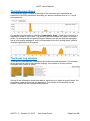
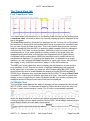
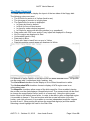
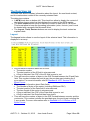
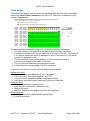
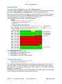
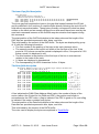
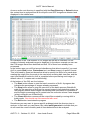
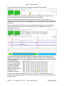
AUFIT & BatchAufit User’s manual By Jean Louis-Guérin (DrCoolZic) Revision 1.3 – October, 2015 AUFIT User’s Manual Table of Content AUFIT & BatchAufit User’s manual ............................................................................ 1 Table of Content ......................................................................................................... 2 Presentation ............................................................................................................... 3 Program Download / Installation ................................................................................. 3 Running Aufit .............................................................................................................. 4 Checking for Update ............................................................................................... 5 Getting Help ............................................................................................................ 5 Loading Image Files ................................................................................................ 5 Command Line Arguments (Aufit batch-mode) ....................................................... 6 Selecting a specific track......................................................................................... 7 Selecting a specific revolution ................................................................................. 7 Tooltips ................................................................................................................... 7 The Histogram Graph.............................................................................................. 8 The Event Log window ............................................................................................ 8 The Track View tab ................................................................................................. 9 Flux Transitions Chart ......................................................................................... 9 Cell Width Chart .................................................................................................. 9 Data Graph ........................................................................................................ 10 ooming and Panning in the Track view .............................................................. 10 The Disk View tab ................................................................................................. 11 The Data View tab................................................................................................. 12 Layout................................................................................................................ 12 Track Buffer ....................................................................................................... 13 Sectors Buffer .................................................................................................... 14 Saving Data View content ................................................................................. 16 The Master View tab ............................................................................................. 17 The Analysis tab.................................................................................................... 18 Protection Analysis ............................................................................................ 18 Format Analysis ................................................................................................. 19 The Save Image tab .............................................................................................. 20 BatchAufit Program .................................................................................................. 21 Checking Quality of generated images ..................................................................... 23 Cleaning ................................................................................................................ 23 Analyzing Images .................................................................................................. 23 Program History........................................................................................................ 26 AUFIT 1.3 – October 21, 2015 Jean Louis-Guerin Page 2 sur 29 AUFIT User’s Manual Presentation AUFIT is the acronym for Atari Universal Floppy-Disk Image Tool. This document describes the usage of the AUFIT and BatchAufit Programs. The Aufit program analyzes and converts Atari Floppy Disk images. Results from analysis can be displayed using different Graphical and Text windows views. The floppy disk image can also be converted to several formats used by emulators. For example the Aufit program is frequently used to convert input Stream files to a format suitable for Atari emulators. It is for example possible to convert .raw or .scp stream files to the Pasti .stx format used by many Atari emulators. Currently the supported input formats are .scp SuperCard Pro and KryoFlux .raw and the supported output formats are .stx format for protected diskette and .st, .msa for non-protected diskettes as well as .raw stream file Aufit performs deep analysis of floppy disk images and displays very detailed information. For example it is possible to display the disk layout, to detect most of the key disk protections used by a game, or to analyze the quality of the disk image. The analysis of the FD content allows, in some cases, an automatic correction of errors found during imaging. For example it is sometimes possible to correctly save an image with partially damaged sectors. The program has been designed to be as simple as possible to use for casual users only interested in converting files. In fact conversion of images can be done in batch mode without user intervention. However the program also provides powerful features to deeply analyze floppy content for more advanced users. Program Download / Installation The Aufit and BatchAufit programs are available either as installable or as portable applications from http://info-coach.fr/atari/software/pc-projects/Aufit.php: The programs run under Windows Vista SP2, Windows 7 SP1, Windows 8/8.1, and Windows 10. The program requires the Microsoft.NET Framework 4.5 or above. The installable version uses the ClickOnce technology from Microsoft that allows to check for a newer version from Internet. When a new version is available you will be ask if you want to automatically install it. This implies that the program is not installed in the standard location: The ClickOnce deployment of Aufit creates an "Aufit" shortcut in "DrCoolZic" Program Group under Start menu: C:\Users\Your_Login\AppData\Roaming\Microsoft\Windows\Start Menu. And the actual program is actually installed inside the following directory. C:\Users\Your_Login\AppData\Local\Apps\2.0\ To install the program just execute the setup.exe file. The portable version does not uses ClickOnce technology and therefore cannot check for new version. To use the portable version just unpack the complete content of the release in one directory and run the program from there. AUFIT 1.3 – October 21, 2015 Jean Louis-Guerin Page 3 sur 29 AUFIT User’s Manual Running Aufit The program can be started by using the Aufit shortcut provided in the start menu, or by double clicking on an image file associated with the Program. When the program starts you will see the following window: The Aufit windows contains three main regions: The first top row contains: The Load Image button allows to specify an image to load, The Reload button allows to reload an already specified image. Once loaded the name of the image file loaded is displayed next to the Reload button. The Rev field indicates the revolution currently used, as well as the number of revolutions, followed by a – and + sign that allows to select a different revolution number see Selecting a specific revolution. The Screenshot button allows to save a picture of the Aufit window. The Update button checks on the Web if a new version of the program is available (only for the installable version). The Help button displays this document. The second row contains the track grid region on the left and the Histogram / Event Log region on the right. The third row region contains different tabs used for specific functions: Track view, Disk view, Data view, Master view, Analysis, and Save image. AUFIT 1.3 – October 21, 2015 Jean Louis-Guerin Page 4 sur 29 AUFIT User’s Manual Checking for Update When you click the Check Update button, the program check on Internet if a new version is available. If a new version is available you are proposed to install it and restart the program. Getting Help When you click the Help button, the program displays this user’s manual. Loading Image Files After starting Aufit the first thing to do is to load a Floppy disk image. This image can be composed of a single file SuperCopy Pro “.scp” file or of a set of KryoFlux “.raw” files. In the latter case all the .raw files, that compose the image, must be located in a single directory and must all have the same “root” name followed by .TrackNum followed by .Side followed .raw. This is the standard naming convention produced by the dtc program. For example you can have a directory that contains the files: awesome.00.0.raw, awesome.00.1.raw, awesome.01.0.raw etc. To read all these files you just need to click on any of the raw files inside this directory and all the other related files will be automatically read. There are three methods to specify the location of a floppy disk image in Aufit: You can use the Load Image buttons. An open file dialog box will be displayed and you just specify the file to load. The name of the last file opened is saved (even between Aufit sessions). This allows to use the Reload button to reload the last loaded image. You can drag a floppy image file from the Windows Explorer and drop it into the Aufit program main window. You can double click on an image file associated with the Aufit program. This will start the program and load the image. The load operation is performed in two phases: First the file(s) is (are) read: this is a very IO intensive operation Then the image is analyzed: this is a very CPU intensive operation To maximize performance the Aufit program is multi-threaded and will use many cores / threads when available. Note: To fully benefit from the Aufit stream analysis you need to sample an Atari floppy disk with a minimum of at least three revolutions for each track but five is the recommended value. Please refer to the imaging tools documentation to create FD images with 5 revolutions. AUFIT 1.3 – October 21, 2015 Jean Louis-Guerin Page 5 sur 29 AUFIT User’s Manual Command Line Arguments (Aufit batch-mode) The Aufit program can be invoked with command arguments, in that case the program run in “batch-mode”. The following arguments are accepted: -disk: This argument requests Aufit to produce a picture of the disk layout. In that case the optional –scale argument allow to specify a scaling factor for the produce image. -scale <scale_value>: This arguments is only useful when the –disk argument is used. The scale_value is used to scale the image produced. When scale is not specified a default value of 1.4 is used. -protections: This argument is used to request Aufit to produce a text file that lists all the protections detected. -save <image_type>: This argument is used to request Aufit to produce an output image. The image type specify the type of image. Currently only stx is supported. -suffix <suffix_name>: The “suffix_name” argument is used to compose the name of the output files produced by Aufit in auto-mode (see below). These arguments must be followed by the name of the input image file to analyze. If this name contains spaces it must be enclosed in double quotes. Whenever optional argument are specified in the command line (other than the image file name) the Aufit program is automatically run in batch-mode. In this mode the program executes the different operations requested by the arguments and then terminates. During execution of Aufit in batch-mode it is recommended, for performance reason, not to place the mouse cursor on top of Aufit’s window. For example the following line: Aufit.exe –disk_view –scale 2.0 –save stx –suffix aufit_1.0 “c:\awesome disk1.scp” Invokes Aufit in batch-mode requesting a disk picture and a stx pasti file. The name of the output files produced are the following: Disk image: base_name.disk.suffix_name.png Protections: base_name.protections.suffix_name.txt STX file: base_name.image.suffix_name.stx The base name depends of the type of the input image. For a .scp files the base name is directly the input name. For example if the input is c:\awesome\awesome_d1.scp the base name is the same. Kryoflux raw files are located in a directory that contains all the raw files. For example the directory c:\awesome\awesome_d1 contains the tracks: track00.0.raw, track00.1.raw, track01.0.raw etc. In that case the base name is c:\awesome\awesome_d1.raw Examples of output: c:\awesome\awesome_d1.scp.disk.aufit_1.0.png c:\awesome\awesome_d1.raw.disk.aufit_1.0.png It is therefore possible to create a command file that, for example, finds the floppy disk images in a directory tree and invoke Aufit with the right parameters. As DOS command files are not easy to write I also provide the BatchAufit program, with a nice GUI, that automatically invokes Aufit in batch-mode with the appropriate parameters for processing a tree of FD images. AUFIT 1.3 – October 21, 2015 Jean Louis-Guerin Page 6 sur 29 AUFIT User’s Manual Selecting a specific track Once the FD image is loaded the information for the first track of the disk is displayed in the different graphs. In the top left corner of the Aufit window you find two grids (one for each side of the floppy) that are composed of track selection buttons. Each grid element correspond to a track and the color of the background used gives information about the analyzed track: Lime green for normal tracks, Orange for protected tracks, Blue for tracks without normal sector but that have data following a 3 sync mark sequence. This usually indicates a data track, Light blue for tracks with possible data detected but no sync sequence, Slate gray for unformatted/empty tracks, White indicates tracks that have not be imaged. The currently selected track button is identified with a larger black border around the button. You can click on any button of the track grid (except non imaged track) to select a specific track. Once a track grid is “active” (for example by clicking on a track selection button) you can change selection from one track to its neighbor by using the four direction keys (left, right, up, down) of your keyboard. Selecting a new track will update the different views. Selecting a specific revolution You can select a specific revolution among the one sampled with the + and - buttons located at the upper right corner of the program window. Selecting a specific revolution affects the information displayed in the different graphs. Tooltips Almost all visual objects in Aufit have an associated tooltip. For example place your mouse over a button or a checkbox and a short explanation about usage of this object is provided as long as you leave the mouse over it. For graphs you will find an image with a question mark “?” on the top left of the graph. Place the mouse over this image and a tooltip will show up that gives indication about the content of the graph. AUFIT 1.3 – October 21, 2015 Jean Louis-Guerin Page 7 sur 29 AUFIT User’s Manual The Histogram Graph The histogram graph, located at the right of the selection grid, represents the repartition of the flux transitions. Normally you should see three pics at 4, 6, and 8 microseconds. It is sometimes interesting to click the “Logarithmic Scale” check box to switch to a logarithmic scale on the Y axis. This allow to see information not visible on a linear scale. For example with the game Dungeon Master you will see that the histogram has a lot of entries between 4 and 6 microsecond due to the “sliding fluxes” pattern used as a protection for this game. The Event Log window The Event Log tab displays information about the executed command. For example when selecting a track it indicates the entropy, the number of fluxes, and the histogram size (max flux value). On top of the information mentioned above, each time you select a specific track, the protections used for this track are displayed. The content of this window can be cleared / saved with the corresponding buttons. AUFIT 1.3 – October 21, 2015 Jean Louis-Guerin Page 8 sur 29 AUFIT User’s Manual The Track View tab Flux Transitions Chart The unprocessed flux transitions (i.e. flux directly read from the file) are displayed as a scattered chart. Information about the currently displayed track is displayed at the top of this graph. The Limit Flux check box limits the flux displayed on the Y axis to 10 µs. By default this checkbox is checked for unformatted track and is unchecked for formatted track but you can change its state at all time. This is very useful when the track contains long flux transitions (like with NFA) to keep the graph readable. Both the Histogram chart and the Flux Chart use this checkbox. Note that in limit flux mode if some transitions above 10 µs exists (therefore located outside of the graph) they are displayed as big black dots on the border (see highlighted dots in graph above). A standard track contains about 40000 flux transitions and by default all the flux transitions are displayed. To speed up the display time, for example on a slower machine, you can uncheck the Detail check box in upper right corner, this will limit the display to only 10000 flux transitions (about ¼ of the flux transitions). The O/E (odd / even) check box allow to display the odd transition in blue and the even transition in red. This can be useful to highlight unbalanced read channels. In the upper right of this chart you have two check boxes called A1 & C2. These check boxes are used to enable/disable the display of the A1 ($4489) and 0xC2 ($5224) Sync Marks as they would be detected by the WD1772 using a Read Track command (i.e. with the sync detector activated at all time). You need to refresh the display to see or hide the sync marks. By default the A1 sync marks (red lines) are displayed and the C2 sync marks (blue lines) are not displayed. Cell Width Chart The Cell Width chart displays the width of decoded cell as computed by the internal WD1772 DPLL clock. The nominal cell width is 2000ns but this value can vary a lot for over / under clocked sectors / tracks. The Y scale is automatically adjusted. When the Avg checkbox is checked (the default) the graph displays a smoothed running average of the bit width computed by the DPLL. When Avg is unchecked the graph display directly the cell width unprocessed. AUFIT 1.3 – October 21, 2015 Jean Louis-Guerin Page 9 sur 29 AUFIT User’s Manual The Cell Width normally stays relatively stable around the 2000ns period but for protection like Copylock usually the values goes from 2000 to 2100 (5% increase) inside a sector. Some protections overclock or underclock the complete track. Data Graph This graph displays all the sectors found on a track: The ID field is displayed in yellow (you need to zoom to see it), The Intra-gap field is displayed in light green, The Data field is displayed in blue. The data field color can change from Blue to Aqua (lighter blue) for under clocked sector, Deep Sky Blue for overclocked sectors, Purple for sector with bit width variation (e.g. speedlock). Data sectors with fuzzy bits have an orange border and data sectors with CRC error have a red border. If you place the cursor over a sector in the data graph, a tool tip shows up and detailed information about the sector is displayed. The Data graph information uses a complex algorithm (mixture of read track, read address, and read sector) to display correctly “complex” tracks containing protection like: Sector within sector, tracks with large number of sectors, tracks with one sector, etc. “Out of band” (OOB) flux transitions (e.g. larger than 8300 µs) usually indicates splice bytes. It is difficult to see them in the transition graph. Therefore OOB (only if located in the GAP area) are displayed as red lines in the data graph. If you place the cursor over one of this red line a tool tip shows up and indicates the exact position and the length of this out of band transition. Zooming and Panning in the Track view When the flux chart is not zoomed you can use the left mouse button to define a zoom area (zoom in both in x and y directions). Click on a first point to start the definition of the area, keep the mouse button down and move to a second point to define a zoom area. A rubber band box is drawn that delimitates the area and when the left button is released the graph is zoomed in the area defined. The scales displayed on both x and y axis are automatically adjusted function of the zoom factor. Once zoomed a click with the left button allow to pan the graph. Click any point in the flux graph with the left button and while keeping the button down move the cursor. The image of the graph dynamically moves with the cursor. When you release the mouse button, the graph and the axis position are updated. You can further zoom-in or zoom-out by using the mouse wheel. If you want to reset the graphs to un-zoomed state click anywhere in the Flux chart with the right mouse button (this is also the way to force a redisplay). Note that the same zoom factor is used to update the flux chart, the clock chart, and the data chart. Therefore these three graphs always stay synchronized. You must place the mouse on top of the flux chart to pan and zoom the charts. AUFIT 1.3 – October 21, 2015 Jean Louis-Guerin Page 10 sur 29 AUFIT User’s Manual The Disk View tab The Disk View tab allow to display the layout of the two sides of the floppy disk. The following colors are used: The ID field of a sector is in Yellow (hard to see) The Intra-gap of a sector is in light green The Data field of a sector is displayed: In Deep sky blue by default In Blue for over clocked sector In Aqua for under clocked segment In Purple for sector with bit-rate variation (e.g. speedlock) Data sector with CRC error and/or Fuzzy bytes are displayed in Orange No Flux region are displayed in Red Unformatted track in Gray Data track in Blue Track with “data in band” but no sync in Yellow Data bits outside normal range are displayed in White It is possible to save a picture of the layout with the Save Picture button. The picture can be saved with 3 resolutions (high, medium, low). The Out of Band checkbox forces display of Out of Band transitions in white. The Unformatted NFA checkbox forces to display of NFA region even in an unformatted track. The Magnifier checkbox allow usage of the disk magnifier. Once enabled, placing the mouse over the disk displays a magnified picture. The mouse wheel can be used to change the magnification factor (zoom-in or zoom-out). Using the right mouse button reset to the default zoom factor. In order to be able to save a magnified region it is possible to freeze it. This can be done with the mouse left button (one click freeze, next click unfreeze). It is possible to use two independent magnifier regions for side 0 and 1. When saving the picture the magnified region(s) are also saved. Selecting a track highlight the track in the Disk View. AUFIT 1.3 – October 21, 2015 Jean Louis-Guerin Page 11 sur 29 AUFIT User’s Manual The Data View tab The Data view allow to display information about the layout, the read track content, and the read sectors content of the currently selected track. The data view contains A MFM check box on bottom left. This check box allow to display the content of the buffers plus an extra line that displays the content of the MFM register. The Save content button allow to save the content of data view in .rtf format. This format allow to keep the formatting information (color, font etc.) and it must be loaded with a program like Microsoft Word. The Layout, Track, Sectors buttons are used to display the track content as explain below. Layout The Layout button allows to see the layout of the selected track. This information is displayed in an array. We first have information about the ID field: The sector number The start position of the ID field in microseconds A flag to indicate if the CRC of the ID field is good or not Then we have the number of bytes in the GAP located between the ID and Data field. This number includes the post-id gap, the pre-data gap including the 3 sync marks. For more information refer to Standard 9-10-11 Sectors of 512 Bytes Format Then we have information about Data fields The Number of bytes of the sector (including DAM and CRC) The start position of the Data field in microseconds The time length of the sector in microseconds. A flag to indicate if the CRC of the Data field is good or not A flag to indicate if the Data field has fuzzy bytes Then we have the number of bytes in the GAP located between a sector and the next sector. This number includes the post-data gap, the pre-id gap including the 3 sync marks. For more information refer to Standard 9-10-11 Sectors of 512 Bytes Format. AUFIT 1.3 – October 21, 2015 Jean Louis-Guerin Page 12 sur 29 AUFIT User’s Manual Track Buffer The track buffer displays the content of the selected track as they would have been read by the Read Track Command of the WD1772. The buffer is displayed if you click the Track button. M:\Atari\FDIMAGES\FLUX\Airborne Ranger (brume)\KF\Airborne Ranger disk A Track 00.0 6285 bytes Length 199973 µs START Bit=0 Byte=0 Time=0,00 ms LENGTH Bit=183588 Byte=6285 Time=199973,51 µs 00000 00016 00032 00048 00064 00080 00096 00112 00128 00144 00160 00176 00192 00208 00224 2000 1992 1988 2000 1992 2000 2007 2015 2015 2015 2015 2000 2015 2015 2015 000031 000525 001052 001564 002077 002590 003103 003617 004130 004643 005157 005671 006184 006698 007211 21 C2 4E 00 60 02 00 00 00 00 00 00 00 00 00 21 A1 4E 00 38 70 00 00 00 00 00 00 00 00 00 21 A1 4E 00 00 00 00 00 00 00 00 00 00 00 00 21 FE 4E 00 1C 20 00 00 00 00 00 00 00 00 00 21 00 4E 00 00 03 00 00 00 00 00 00 00 00 00 21 00 4E 00 00 00 00 00 00 00 00 00 00 00 00 21 01 4E 00 00 05 00 00 00 00 00 00 00 00 00 21 02 4E 00 00 00 00 00 00 00 00 00 00 00 00 FF CA 4E 00 08 0A 00 00 00 00 00 00 00 00 00 FF 6F 4E 00 80 00 00 00 00 00 00 00 00 00 00 FF 4E 4E 00 3F 01 00 4E 00 00 00 00 00 00 00 FF 4E 4E 00 00 00 00 75 00 00 00 00 00 00 00 FF 4E 4E 14 02 00 00 00 00 00 00 00 00 00 00 FF 4E 4E A1 02 00 00 00 00 00 00 00 00 00 00 FF 4E 4E A1 01 26 00 00 00 00 00 00 00 00 00 FE 4E 4E FB 00 3C 00 00 00 00 00 00 00 00 00 !!!!!!!!ÿÿÿÿÿÿÿþ ¡¡þ....ÊoNNNNNN NNNNNNNNNNNNNNNN .............¡¡û `8........?..... .p. ..........&< ................ ..........Nu.... ................ ................ ................ ................ ................ ................ ................ The data bytes are displayed by group of 16 with the following information: The first number is the position of the byte in the buffer (decimal value) The second number is the cell bit-width of the first byte of the line. If the width is 2.5% above normal the period is displayed in blue, if the period is 2.5% below normal it is displayed in red. The third number is the starting position of the first byte of the line in microsecond relative to the index of the track. The 16 bytes are displayed in hexadecimal format Followed by the corresponding 16 ASCII characters. Colors and font style are used to provide additional information. Background color: Light blue for invalid characters (F5-F7) into gaps Coral for no flux area (MFM 0x0000 / 0xFFFF) Yellow for Sync characters (MFM 0x4489 and 0x5224) Light green for bytes located inside an ID field or a Data field. Character color: Red for 0x4489 Sync characters (A1) Navy blue for 0x5224Sync characters (C2) Blue for ID bytes Black for Data and intra-gap byte and for inter-gap byte Bold characters: For Sync characters (MFM 0x4489 and 0x5224) For Id field content AUFIT 1.3 – October 21, 2015 Jean Louis-Guerin Page 13 sur 29 AUFIT User’s Manual Sectors Buffer The sector buffer is displayed if you click the Sector button. The sector buffer displays the content of the selected track as they would have been read by the Read Address and Read Sector commands of the WD1772. But it also includes information that can’t be read by the WD1772: the GAP contents. This information is most of the time different from what is read with the read track command because of the false sync problem of the WD1772. The information for each sector is displayed like this Sector 11 ID Field: IAM=FE T=00 H=00 S=0B L=02 CRC=A425 Good START Bit=95357 Byte=5960 Time=190,10 ms LENGTH Bit=112 Byte=7 Time=223,66 µs Inner GAP Field: START Bit=95469 Byte=5967 Time=190,33 ms LENGTH Bit=496 Byte=28 Time=987,94 µs 05967 1988 190327 4E 4E 4E 4E 4E 4E 4E 4E 4E 4E 4E 4E 4E 4E 4E 4E NNNNNNNNNNNNNNNN 05983 2000 190837 4E 4E 4E 4E 4E 4E 00 00 00 00 00 00 NNNNNN...... DATA Field: DAM=FB 512 bytes start at 191315µs length 16480 µs CRC=FFFF Bad Fuzzy sector START Bit=95965 Byte=5998 Time=191,32 ms LENGTH Bit=8240 Byte=512 Time=16480,59 µs 05998 2000 191348 00 00 00 00 00 00 00 00 A1 A1 A1 FE 00 00 0C 02 ........¡¡¡þ.... 06014 1984 191859 BC 33 4E 4E 4E 4E 4E 4E 4E 4E 78 54 C5 BC 66 2B ¼3NNNNNNNNxTżf+ 06030 1984 192368 71 BD 4E 4E 4E 4E 4E 4E 4E 4E FF FF FF FF FF FE q½NNNNNNNNÿÿÿÿÿþ 06046 2000 192880 14 14 14 00 FF FF FF FF FF FF FF FF FF FF FF FF ....ÿÿÿÿÿÿÿÿÿÿÿÿ 06062 1984 193388 FF FF FF FF FF FF FF FF FF FF FF FF FF FF FF FF ÿÿÿÿÿÿÿÿÿÿÿÿÿÿÿÿ 06078 1984 193897 FF FF FF FF FF FF FF FF FF FF C0 00 00 00 00 00 ÿÿÿÿÿÿÿÿÿÿÀ..... 06094 1992 194192 00 00 00 00 00 00 00 00 00 00 00 00 00 00 00 00 ................ 06110 1992 194192 00 00 00 00 00 00 00 00 00 00 00 00 00 00 00 00 ................ 06126 1992 194192 00 00 00 00 00 00 00 00 00 00 00 00 00 00 00 00 ................ 06142 1992 194192 00 00 00 00 00 00 00 00 00 00 00 00 00 00 00 00 ................ 06158 1992 194192 00 00 00 00 00 00 00 00 00 00 00 00 00 00 00 00 ................ 06174 1992 194192 00 00 00 00 00 00 00 00 00 00 00 00 00 00 00 00 ................ 06190 1992 194192 00 00 00 00 00 00 00 00 00 00 00 00 00 00 00 00 ................ 06206 1992 194192 00 00 00 00 00 00 00 00 00 00 00 00 00 00 00 00 ................ 06222 1992 194192 00 00 00 00 00 00 00 00 00 00 00 00 00 00 00 00 ................ 06238 1992 194192 00 00 00 00 00 00 00 00 00 00 00 00 00 00 00 10 ................ 06254 1984 199525 90 90 90 90 90 90 90 90 90 90 90 90 90 90 90 90 ................ 06270 1984 200035 90 90 90 90 90 90 90 FF FF FF FF FF FF FF FF 0A .......ÿÿÿÿÿÿÿÿ. 06286 2000 200549 0A 0A 00 FF FF FE 7C 10 80 10 90 90 90 90 90 90 ...ÿÿþ|......... 06302 2000 201056 90 90 90 90 90 90 90 90 90 90 90 90 90 90 90 FF For each sector we have A description for the ID Field A description for the Inner GAP Field A description for the Data field A description for the Post data Gap field The ID Field description ID Field: IAM=FE T=00 H=00 S=01 L=02 CRC=6FCA Good START Bit=317 Byte=20 Time=0,64 ms LENGTH Bit=112 Byte=7 Time=223,57 µs The description includes a line with the IAM (ID Address Mark) value, the Track (T) value, the Head (H) value, the Sector (S) value, the encoded data Length value (L), the CRC value, an indication showing if the CRC is good or not. All these values are displayed in hexadecimal. Followed by the start position of the ID field relative to the index pulse and the length of the ID sector field expressed in bits, bytes, and time. AUFIT 1.3 – October 21, 2015 Jean Louis-Guerin Page 14 sur 29 AUFIT User’s Manual The Inner Gap field description Inner GAP Field: START Bit=429 Byte=27 Time=0,86 ms LENGTH Bit=592 Byte=34 Time=1182,32 µs 00027 2000 000861 4E 4E 4E 4E 4E 4E 4E 4E 4E 4E 4E 4E 4E 4E 4E 4E 00043 2000 001372 4E 4E 4E 4E 4E 4E 00 00 00 00 00 00 00 00 00 00 00059 2000 001885 00 00 NNNNNNNNNNNNNNNN NNNNNN.......... .. The inner gap field contains the bytes in the gap field located between the ID field and the data field. Aufit continue to read the bytes directly following the end of the ID field without resynchronization. These bytes normally correspond to what has been written on the track and are usually different from what would have been read by the read track command because of the 0x5224 resynchronization that happen during this command. The start position of the GAP field relative to the index pulse and the length of the GAP field are provided expressed in bits, bytes, and time. This is followed by the content of the GAP buffer. The bytes are displayed by group of 16 with the following information: The first number is the position of the byte in the track (decimal value) The second number is the half bit cell width of the first byte of the line. If the period is 2.5% above normal the period is displayed in blue, if the period is 2.5% below normal it is displayed in red. The third number is the position of the first byte of the line in microsecond relative to the index of the track. 16 bytes are displayed in hexadecimal The corresponding 16 ASCII characters for the 16 bytes. The Data field description DATA Field: DAM=FB 512 bytes start at 21038µs length 16415µs CRC=D902 START Bit=10525 Byte=658 Time=21,04 ms LENGTH Bit=8240 Byte=512 Time=16415,45 µs 00658 1984 021072 00 00 00 FF 4F 00 05 60 00 FF 8F 00 09 A0 00 0B 00674 1984 021581 C0 00 0D E0 00 0F 00 01 11 20 01 13 40 01 15 60 00690 1984 022089 01 17 80 01 19 A0 01 1B C0 01 1D E0 01 1F 00 02 00706 1989 022598 21 20 02 23 40 02 25 60 02 27 80 02 29 A0 02 2B 00722 1984 023109 C0 02 2D E0 02 2F 00 03 31 20 03 33 40 03 35 60 00738 1984 023616 03 37 80 03 39 A0 03 3B C0 03 3D E0 03 3F 00 04 … 01090 1984 034844 21 F1 FF FF 4F 12 25 61 12 27 81 12 29 A1 12 2B 01106 1984 035354 C1 12 2D E1 12 2F 01 13 31 21 13 33 41 13 35 61 01122 1984 035863 13 37 81 13 39 A1 13 3B C1 13 3D E1 13 3F 01 14 01138 1984 036372 41 21 14 FF 4F 14 FF FF FF 47 F1 FF 49 A1 14 4B 01154 1984 036880 C1 14 4D E1 14 4F 01 15 FF 2F 15 53 41 15 55 61 Good ...ÿO..`.ÿ... .. À..à..... ..@..` ..... ..À..à.... ! .#@.%`.'..) .+ À.-à./..1 [email protected]` .7..9 .;À.=à.?.. !ñÿÿO.%a.'..)¡.+ Á.-á./..1!.3A.5a .7..9¡.;Á.=á.?.. A!.ÿO.ÿÿÿGñÿI¡.K Á.Má.O..ÿ/.SA.Ua A line indicates the DAM (Data Address Mark) value, the number of bytes of the sector (without the 3 bytes for the DAM and CRC), the position and length in microseconds, the CRC value, a flag to indicate if the CRC is good or not, and a flag to indicate if the sector contains fuzzy bytes. The start position of the Data field relative to the index pulse and the length of the Data field are provided expressed in bits, bytes, and time. This is followed by the content of the DATA buffer. The color used to display the bytes are explained in Track Buffer. AUFIT 1.3 – October 21, 2015 Jean Louis-Guerin Page 15 sur 29 AUFIT User’s Manual If some fuzzy bytes have been found in a sector a “fuzzy mask” buffer is also displayed. Sector 11 Fuzzy Bytes Mask array 5998 00 00 00 00 00 00 00 00 00 00 6014 00 00 00 00 00 00 00 00 00 00 6030 00 00 00 00 00 00 00 00 00 00 6046 00 00 00 00 00 00 00 00 00 00 … 6222 00 00 00 00 00 00 00 00 00 00 6238 00 00 00 00 00 00 00 00 00 00 6254 DE DE DE DE DE DE DE DE DE DE 6270 DE DE DE DE DE DE DE FF FF FF 6286 AB AB FE FF FF FF 7E DA EF 5E 6302 DE DE DE DE DE DE DE DE DE DE … 00 00 00 00 00 00 00 00 00 00 00 00 00 00 00 00 00 00 00 00 00 00 00 00 00 00 DE FF DE DE 00 00 DE FF DE DE 00 00 DE FF DE DE 00 00 DE FF DE DE 00 81 DE FF DE DE 00 5E DE AB DE FF To find fuzzy bytes the Aufit program read the same sector multiple times from different revolutions. If the content of a byte in the same position is different the mask value is the result of a xor operation. The mask array combines the fuzzy bytes found on all revolutions. Mask[offset] = (Sector_read_1[offset] ^ Sector_read_2[offset]) Thus same value (1&1 or 0&0) gives a result of zero and different value (0&1 or 1&0) gives a result of one. For example if the same byte is read one time as 0000 1111 and the next time as 0101 0101 the mask will be 0101 1010. This mask can then be used to emulate fuzzy bits as follow: FuzzyByte[offset] = (Sector[offset] & Mask[offset]) | (rand() & Mask[offset]) Where rand() is a function that randomly returns true or false. If the fuzzy bytes are all of type Dungeon Master (i.e. the transitions are located in uncertain areas), an indication is provided. 73 fuzzy bytes of type Dungeon Master / Chaos Strike Back found The Post data Gap Field Post GAP Field: START Bit=9261 Byte=579 Time=18,53 ms LENGTH Bit=560 Byte=32 Time=1115,28 µs 00579 1988 018525 4E 4E 4E 4E 4E 4E 4E 4E 4E 4E 4E 4E 4E 4E 4E 4E 00595 1988 019035 4E 4E 4E 4E 4E 4E 4E 4E 00 00 00 00 00 00 00 00 NNNNNNNNNNNNNNNN NNNNNNNN...... The post data gap field contains the bytes in the gap located after the data field. Aufit continue to read the bytes directly following the end of the DATA field without resynchronization. These bytes normally correspond to what has been written on the track and are usually different from what would have been read by the read track command because of the 0x5224 resynchronization that happen during this command. The start position of the GAP field relative to the index pulse and the length of the GAP field are provided expressed in bits, bytes, and time. This is followed by the content of the GAP buffer. Saving Data View content For any of the data view buffer (Layout / Track / Sectors) it is possible to save the buffer in RTF format using the Save button. The RTF format allow to keep all formatting information for example the font weight, the color, etc. You can use a RTF reader like Microsoft Word to load the RTF format and save it for example in PDF. AUFIT 1.3 – October 21, 2015 Jean Louis-Guerin Page 16 sur 29 AUFIT User’s Manual The Master View tab The Master view displays floppy disk mastering information. Not yet implemented – Do not use The mastering information contains the disk data, how it is stored (and hence how to write it back), and also other things needed to store copy protection (like how dense the data is at any part of each track). It is interesting to note that this information does not contain directly detailed information often found in other preservation formats. For example the timing information measured by an image preservation tool is not stored but the “format description” can for example indicate that specific sectors of a track uses a well-known bit-cell density variation. The result is therefore perfect as the timings are not subject to measurement errors. The mastering information can be saved in IPF format and this allow to use the KryoFlux mastering system to write a perfect diskette even if the input image generated by a KryoFlux or SuperCard Pro board has lots of imperfections. To generate the mastering information Aufit performs an automatic recognition of known disk-formats. Finding the original mastering description can be compared to breaking a vault combination lock: it is a very hard process but once done you know that you have a perfect result. T00.0 STD_MFM_9x512 9 Blocks 6250 Bytes (xxx Gap + yyy Data) Auto Density Start @ zzzz B0 ID_DATA Sector 1 Length 512 SYNC 3 MFM Word 4489 4489 4489 HEAD 7 DEC Bytes FE 00 00 01 02 CA 6F IGAP 34 DEC Bytes SYNC 3 MFM Word 4489 4489 4489 DATA 515 DEC Bytes B1 ID_DATA Sector 2 Length 512 SYNC 3 MFM Word 4489 4489 4489 HEAD 7 DEC Bytes FE 00 00 01 02 CA 6F IGAP 34 DEC Bytes SYNC 3 MFM Word 4489 4489 4489 DATA 515 DEC Bytes Track T00.0 6250 Bytes (xxx Gap + yyy Data) Density Auto First sector 1 starts @ zzzz Recognized as STD_MFM_9x512 AUFIT 1.3 – October 21, 2015 Jean Louis-Guerin Page 17 sur 29 AUFIT User’s Manual The Analysis tab Currently the Analysis view only contains the protection analysis. Other analysis will be added at later time. Protection Analysis To perform a protection analysis just click the Protections button. The result of the analysis of all the track is displayed: To save the result of analysis in text format you can use the Save button. Protection analysis for M:\Atari\FDIMAGES\FLUX\Dragonflight\SCP\Dragonflight - A.scp T00.0 T00.0 T00.0 T00.0 T00.0 T00.0 T00.0 T00.0 T00.0 T00.0 T00.0 T01.0 T01.0 T01.0 T01.0 T01.0 T01.0 T01.0 T01.0 T01.0 T01.0 T01.0 T01.0 hidden data in GAP (dragonflight) S1 invalid head/side number 48 (IHN) S2 invalid head/side number 48 (IHN) S3 invalid head/side number 48 (IHN) S4 invalid head/side number 48 (IHN) S5 invalid head/side number 48 (IHN) S6 invalid head/side number 48 (IHN) S7 invalid head/side number 48 (IHN) S8 invalid head/side number 48 (IHN) S9 invalid head/side number 48 (IHN) S10 invalid head/side number 48 (IHN) hidden data in GAP (dragonflight) S1 invalid track number 178 (ITN) S1 invalid head/side number 48 (IHN) S2 invalid track number 178 (ITN) S2 invalid head/side number 48 (IHN) S3 invalid track number 178 (ITN) S3 invalid head/side number 48 (IHN) S4 invalid track number 178 (ITN) S4 invalid head/side number 48 (IHN) S5 invalid track number 178 (ITN) S5 invalid head/side number 48 (IHN) S6 invalid track number 178 (ITN) The following protections are currently analyzed. Track Protections SHT Short track LGT Long track NFA (No Flux Area) SHT-DBI Shifted track Data beyond index SHT-DOI Shifted track Data over index, SHT-IBI Shifted track ID beyond index, SHT-IOI Shifted track ID over index IDG Invalid data into GAP HDG Hidden data into Gap : “Dragonflight & Jupiter Masterdrive protections ISS Invalid Sync Sequence Sector Protections DSN Duplicate sector number IIF-NDI Invalid ID Field Nonstandard IAM IIF-ITN Invalid ID Field Invalid track number IIF-IHN Invalid ID Field Invalid Head Number IIF-ISN Invalid ID Field Invalid Sector number IIF-ISL Invalid ID Field Invalid sector Length IIF-ICE Invalid ID Field ID CRC error SWS Sector within sector DCE Data CRC Error AUFIT 1.3 – October 21, 2015 Jean Louis-Guerin Page 18 sur 29 AUFIT User’s Manual FZS Fuzzy Sector NSD Nonstandard DAM LGS Long sector SHS Short sector SBV Sector bit rate variation SND Sector with no data Non sequential sector number (for ST format) Nonstandard sector size (for ST format) For more details about these protections please refer to my document Atari Floppy Disk Copy Protection. Note that protections are also analyzed in other views when a Track is selected. You can see the result in the Information window. Remember that a track that contains protection or error is displayed in Orange in the track grid. Format Analysis TODO AUFIT 1.3 – October 21, 2015 Jean Louis-Guerin Page 19 sur 29 AUFIT User’s Manual The Save Image tab When you select this tab you are presented with information about the possible format you can use to save the current image. Currently three families of formats exist: The non-protected byte formats includes: ST, MSA, DIM The protected byte format: STX, IPF The bit stream format: RAW Aufit includes an auto-recovery feature. When you write the content of a floppy disk that contains sector’s errors the program will try to recover the information about this sector from another revolution. You first have to select the output format you want to use from a combo box on the left. If it is not possible to use a specific format with the current data (for example ST format for floppy disk using protection) it will be grayed. When you click the Write Image button a form open and ask you the location and the name of the file to write. If the file already exist a window will pop up and ask you if you want to replace the existing file. As soon as you close this form the output file is written and some information is displayed in the main window including error recovered and potential problems. Reminder: In order to produce a correct file you must use images with data for at least three revolutions but a value of five is recommended especially for floppies in bad condition. If not enough data (revolutions) have been imaged a window will pop up and warn you. You are still offer the capability to force writing the file. Normally single sided / double sided detection is performed automatically by Aufit. If you are getting error messages in Steem that an image of a track is missing on side 1 of the floppy image you may need to force Aufit to write file for double sided disk. For that matter please check the Force DS check Box. When the Optimize check box is checked (the default) Aufit will write “compressed” file (smaller file size) for the STX and MSA format. The Debug and WriteSync check boxes are for debug purpose and normally you do not have to use them. The raw stream format You can now write the KF Raw format. This is only useful if you want to convert a stream file from SCP to RAW. In that case Aufit creates a directory named by concatenating .scp file name with .conv. For example if the input is warrior_d.scp the output directory will be warrior_d.scp.conv. This directory will contains many .raw files (one per track). If the directory that contains the Aufit.exe executable also contain the Kryoflux dtc.exe executable, Aufit will automatically call the dtc.exe program with the right parameters to produce a CTR file from the created raw files. The name of the crt file is the name of the scp file with .conv.ctr appended. For example warrior_d.scp.conv.ctr AUFIT 1.3 – October 21, 2015 Jean Louis-Guerin Page 20 sur 29 AUFIT User’s Manual BatchAufit Program As mentioned in the Command Line Arguments (Aufit batch-mode) section it is possible to run the Aufit program in batch mode to automatically produce specific outputs without user intervention. Always use the BatchAufit program that matches the Aufit program as from time to time the command line argument are changed. The BatchAufit program allows to automatically detect all FD images located inside a directory tree and to invoke the Aufit program in auto-mode for all the detected images not yet processed. The GUI is composed of three area The top area contains a button that allow to specify the root directory of the tree where you want to search for Kryoflux and SCP FD images. When the Root Directory button is clicked a dialog box opens to specify the location of the root directory tree. Once specified the name of the root directory is displayed in a text box on the right of the Reload button. The Reload button forces to re-read the last specified tree location. This information is saved between sessions and therefore it is possible to continue the processing of images in separate sessions. The top area also contains a Save Log button that allows to save the content of the display area. This allow to save for example the result of analysis of a tree or the result of running Aufit in batch mode. AUFIT 1.3 – October 21, 2015 Jean Louis-Guerin Page 21 sur 29 AUFIT User’s Manual As soon as the root directory is specified with the Root Directory or Reload buttons the content tree is analyzed and all the Kryoflux and SCP images are detected and displayed in the middle area. An indication of the Total number of FD images as well as an indication on the number of already analyzed images is displayed. In the above example we can see that 708 images have been detected and that 130 of them have already been processed. In the bottom area you will find several checkboxes that allow to specify if you want Aufit to create Disk picture, Protections text, and Save image in a specific format. This is followed by three text boxes that allow to specify the suffix to be used when creating the output files, the scale to be used when creating disk view files, and the max time BatchAufit waits for Aufit to complete before processing next image (a default value of -1 means wait un-definitively). At the bottom of the GUI are four buttons: The Start button allows to start the batch execution of Aufit. A progress bar indicates the percentage of images already processed. The Stop button allow to stop the execution of the batch process. BatchAufit waits for the execution of Aufit on the current image to terminate then stops. As the program detects what images has already been processed it is possible to stop the batch processing and to restart later the execution where it was stopped (even in different run of BatchAufit). The Clean All button removes all the output files created by running Aufit in batch mode. You should use this command with care! The Exit button terminates the program Sometimes you may want to ignore specific subtrees inside the directory tree to analyze. In that case you can place a file called aufit.ignore.txt to indicate that you do not want the current directory and all its subdirectories to be analyzed. AUFIT 1.3 – October 21, 2015 Jean Louis-Guerin Page 22 sur 29 AUFIT User’s Manual Checking Quality of generated images This section discuss several questions around the quality of Floppy Disk images created with devices like KryoFlux or SuperCard Pro. To some extent the quality of the image is only related to the floppy drives and floppy disks conditions and therefore independent of the imaging device used. Cleaning The first thing you want to do before imaging floppy disks is to clean the floppy drive head and a make sure you have spotlessly clean floppy disk. Cleaning the floppy drive head and cleaning the diskette can make a big difference First always clean the floppy drive head using dedicated cleaning kits as this is a very easy to do operation. Cleaning a floppy disk is a much more painful operation and therefore you can try to image the diskette without cleaning. If during analysis, as explained below, you find problems on the disk image you should clean the floppy diskette. The recommended way is to wipe the surface of the floppy diskette using a Q-Tip impregnated with head cleaning liquid. Normally this liquid evaporate quickly but you can use the other side of the Q-Tip to help dry the liquid in excess. There are numerous site and videos on the net that explain in detail these operations. Important things to know when cleaning a floppy diskette: The side with an etiquette is the “second logical side” (side/head 1) of the diskette The side with the hub that engages with the drive motor is the “first logical side” (side/head 0) of the diskette. So if you find problems on side/head 0 you need to clean the side without the etiquette (what I refer as the back side) and if you find problems with side/head 1 you need to clean the side with the etiquette (what I refer as the front side). Analyzing Images Now let’s move on the heart of the subject: How do I find if the image I have done is of good enough quality? For that matter we use the Aufit program. You first need to read the image you have created as explain in Reading Image Files section. When the program read the image it already display useful information in the Track grids as the background color of each track is an indication of possible problem: A “normal” track has a light green background, an unformatted track has a light gray, and a track with potential problem is displayed in yellow. At this stage only a quick Shannon Entropy analysis is done on the flux transitions histogram and a yellow color usually indicates track with partially unformatted areas or incorrectly imaged track but always require a more complete analysis. AUFIT 1.3 – October 21, 2015 Jean Louis-Guerin Page 23 sur 29 AUFIT User’s Manual For examples here is the result of reading an image of Sherman M4. We can see that we have several tracks with a yellow background. If we click on some of these tracks we will find that in fact they are corrects. But if we click on track 66 we can see than sector one has a lot of “dirty” flux transitions. Thanks to the DPLL these variations can be corrected and we are able to read the sector correctly. This is indicated by the fact that all the sectors read without CRC error. But if we select the track 73 and zoom on the first sector area we can see that we also have dirty flux transitions, but here the DPLL is not capable to decode the information correctly. In this case we can see that the first sector is read with fuzzy bytes (orange box in data chart and indication in the information window). In fact if we further analyze the problem we can find, in the fuzzy mask buffer that only two bytes at position 206 and 214 vary between revolutions! This also why it is recommended to sample at least four revolutions as Aufit always checks fuzzy bytes by comparing the data read for all available revolutions. In this case it seems obvious that is error is not part of a protection but due to a problem on the floppy diskette. In such case you should try to clean the diskette and image it again. AUFIT 1.3 – October 21, 2015 Jean Louis-Guerin Page 24 sur 29 AUFIT User’s Manual We can even look further at the problem. If we click the Sectors Buffer command we can see that on some of the revolutions the CRC is good and on some other revolutions the CRC is bad. Normally a fuzzy byte always result in a CRC error. Therefore this indicates that on some revolutions we have read the correct information. Currently Aufit is not able to use this information to create a working Past file but I may implement this feature in the future. You need to be aware that on an Atari system when reading sectors from a diskette an automatic retry is performed anytime a sector is not read correctly. This retry is transparent to the user and is used more often than you think. Therefore when you have problem clean the floppy and recreate new image, and if this still fails try to recreate the image several times. If the floppy is only marginally not read this may allow you to create a good image. In order to find all possible problems you first need to run the Protection command and for each “protected track” (displayed with a red background in the track grid) you need to check if the problem comes from known protection or from “dirty flux transitions”. Unfortunately it seems very difficult to find out about bad images automatically and this is why you need to do a visual inspection using the different features of the Aufit program. AUFIT 1.3 – October 21, 2015 Jean Louis-Guerin Page 25 sur 29 AUFIT User’s Manual Program History V1.3 October 21, 2015 Major change in the Database -- Typical size of database after Read/Process image is now down to 650 MB instead of 900 MB While reading/processing file the button matrix is now disabled to avoid problems Fix added tool tips to reflect changes In flux transition graph when flux limit is checked, a flux transition bigger than 10000 µs is displayed as big black dots at the border of graph. This indicates the presence of flux transitions beyond the graph limit. Color usage in transition chart has changed: Normal mode: normal=blue, red=violation, green=border Unformatted in black Odd/even mode: blue/red Added Odd/Even checkbox for flux transition chart Added Average checkbox for Clock chart Hack in DPLL to correctly read DM fuzzy bits Added call to DTC.EXE (if present in Aufit executable directory) to automatically write .ctr file from generated KF Raw files. Added KF stream Raw file writer Short/long sectors are now 4% above/below normal instead of 3% Fixed Alternate Realty bug (JMD & DF checking + limit OBB line + stx) Added checkbox that allow to not generate Track Data in stx file Fixed bug of ISS sometimes incorrectly detected. V1.2 August 12, 2015 Changed some command line parameters Added save image type (currently only stx) Definitively Fixed problem of racing conditions in Aufit batch mode Fixed bug for fuzzy bytes on Dungeon Master & Chaos Strike back (DPLL) Fixed bug in writing incorrectly fuzzy bytes in STX for truncated sectors Added Magnifier capability in Disk View Added Tooltips on most objects and charts of Aufit Fixed scale factor for disk snapshot Checking if passed file name exists otherwise exit application Fixed bug in file names All transparent windows in Aufit are now white Added detection of Dungeon Master type of fuzzy bytes Added Data / Time of build in the title bar Fuzzy bytes are now a combination of fuzzy bytes detected for all revolutions In Data View => Sectors detection & display of DM & CSB fuzzy bytes Fixed graphical bug on the tabs of the Aufit main window Information window renames to Event log Fixed bug of Rev number incorrectly reported in Event log Fixed bug of inner and post data gap bytes possibly filtered Out of band in track data content now checking for transitions over 8% in the 3 data bands AUFIT 1.3 – October 21, 2015 Jean Louis-Guerin Page 26 sur 29 AUFIT User’s Manual Corrected bug in Post Gap data (incorrect length for SWS) Aufit.pdf is now located in the install directory. Aufit does not crash but report an error message if help file not found. Bad data in GAP are displayed in DarkOrange (Data View -> Sector command). This can be used to detect sector/track write splice Post GAP information displayed in tool-tip when hovering sector in data chart Fixed bug of incorrect message when canceling image write Fixed bug of image format detection/selection when loading new image V1.1.5671 – July 12, 2015 Added iconized buttons for Update and Help with code behind to check for new version and display user’s manual. Huge change: In the Data view the sector button now displays GAP buffers. The Gap fields contains the bytes located after the ID and the DATA fields. Aufit continue to read the bytes directly following the end of the ID/DATA fields without resynchronization. Splice lines are now limited to flux above 4% in GAP only => red for inner and blue for post gap Fix bug of wrong section detection in random flux. BatchAufit project is now ClickOnce application and Aufit.exe is now automatically installed with BatchAufit. Invalid sync sequence protection is now detected. Major reformatting of the protection messages + added ISS V1.0 May 2015 Improve support of Aufit batch mode BatchAufit : Lots of GUI changes + Added reload button (use last saved directory) + added button to save log file + added MaxProcessTime (default 1). Maximum wait time before Aufit is killed + log now includes: start time, elapsed time, and cpu time + processed, succeeded, failed + renamed suffix to 1.0 + Icon for executable... Save last loaded image name. This allow to reload last analyzed image on next run. Added image name + Aufit version in disk image Processing of line argument to enter batch mode Miscellaneous fixes in Buffer & Disk display Added drawing of splice line (when flux out of range) in Data chart. Added detection of jupiterMasterDRive and dragonflight protections V0.9 February 2015 Support for MSA and ST output format Detection of Drzgonflight & Masterdrive protections Improved display of several charts V0.8 January 2015 - Data View Bug fix: DSR + FDC (see todo) GUI cleaning + Bug fixes (GAP - FDC) removed file association create too many problems Save Window size and position AUFIT 1.3 – October 21, 2015 Jean Louis-Guerin Page 27 sur 29 AUFIT User’s Manual Test Click once publishing Buffer Windows are gone replaced by the Data View tab with better functionalities. V0.7 January 2015 - Auto recovery - Improve Disk view - Lots of bug fix - Auto safe mode for really bad images Added auto safe mode (safe but slower mode) when sector not found + Analysis GUI + Speed DiskGui + Bug fixes Fix DSR bug on sync seq, FDC detect sync at edge of index + bug fixes Fixed 0.6.5476.33179: Crackdown 2D = KF Sector not found Fixed 0.6.5476.18307: Computer Hits V2 - SCP D2 sector missing on some tracks Crackdown SCP D1&D2 crash Auto-recovery feature added to automatically write good pasti Fixed 0.6.5473.34262: Chicago 90 crash Fixed 0.6.5472.17463: Gunship SCP track 21.0 Bad Fuzzy report first sect due to NFA! Fixed 0.6.5473.16121: Barbarian scp d2 invalid file content error cannot display Fix bug Kickoff 2 SCP NFA not decoded correctly (again cant display right info) Fix bug NFA not working for Dr. Doom Revenge (now NFA handled at read time) *** NOTE *** SCP file does not provide information about index position in flux Therefore it is impossible to do something clean when we have NFA over index Fix bug sector not found due to unformatted sectors Crossbow D1, RoadBlaster improve Disk View (cursor display) & speedup Track View V0.6 December 2014 Freeze for Beta release to Brume V0.5 December 2014 Major rewrite of Aufit internals Fix non-working STX for Jupiter master drive, Gunship, P-47 http://www.atariforum.com/viewtopic.php?f=102&t=25854&start=525#p263646 http://www.atariforum.com/viewtopic.php?f=102&t=25854&start=250#p248282 http://www.atariforum.com/viewtopic.php?f=102&t=25854&start=275#p248377 Fixed nasty bug in DSR for Skateball game New Disk Layout display design New Main window layout using tabs for: Track view, Disk view, Content, Analysis, Save Specify file/dir to read = from menu, drag and drop, double click Drawing disk layout now uses multi-threading now reading and processing of flux data is using heavy multi-threading Added out of band flux display in Disk layout window AUFIT 1.3 – October 21, 2015 Jean Louis-Guerin Page 28 sur 29 AUFIT User’s Manual code and documentation cleaning detection of ID over index on top of data over/beyond index optimization of STX file using data from track for sector (save space) support for stream file drop in main window protections rewritten completely - uses new flags on new DS capability to save pictures of main screen and Disk layout Handle correctly intra sector bit width variation FDC speed improvement: all sectors read in one pass in most cases removed read directory and dependency on Ookii.Dialogs.Wpf.dll This version uses new "packed" data structures to be prepared to interface with IPF lib. now flux samples are stored in ns and speed correction is done at reading time Completely rewritten FDC module with more clean routines use modified version of the DSR from IPF library thanks to IFW from SPS changed clock reference to half bit width removed rev=0 capability V0.4b - March 1, 2014 Color scheme changed, improve disk data, fix pre sync data problem, and fix fuzzy assertion error in compare mode. V0.3a February 17, 2014 Check for incomplete information when writing Pasti. Corrected NFA display, improved FDC emulation. More robust: should be able to read corrupted Floppy Disk V0.2c January 22, 2014 – Bug fixes on Pasti Files generated V0.2a January 18, 2014 – Major change is the capability to write Pasti files. This is still experimental. Bug fixes and better read track report. Now Buffer display uses the currently displayed revolution. This allow to compare the decoded data for the different revolutions. V0.1b January 9, 2014 – Fixed one very nasty and tough to find bug. In .Net framework when you click a form to select a file the click event is not flushed and you get it back as a button click ... Also improved memory usage. V0.1a January 9, 2014 – Compared to initial release Protection analysis has been added. So only missing initial features is Pasti write capability. Known problems: Run out of memory easily, GUI freeze with DISK DATA command. V0.0 January 6, 2014 – Initial alpha release on request. AUFIT 1.3 – October 21, 2015 Jean Louis-Guerin Page 29 sur 29


![Atari ST System-on-Chip in VHDL (Author: Lyndon Amsdon) [undated]](http://vs1.manualzilla.com/store/data/005994841_1-cb1a0817df59f22c671df08194997a7c-150x150.png)