1
IBS IL 24 BK-T/U ...
Interfaces (INTERBUS) (Continued)
Branch/Local Bus
Connection
Through data routing
Level
5 V CMOS signal level
Number of Inline terminals that can be connected
Limitation through software
63, max.
Limitation through power supply unit
Maximum logic current consumption of the connected local bus modules:
Imax ≤ 2 A DC
Observe the current consumption of the modules
m
Observe the logic current consumption of each device when configuring an Inline station. It is specified in every terminal-specific data
sheet. The current consumption can differ depending on the individual terminal. The permissible number of devices that can be connected
therefore depends on the specific station structure.
Functional
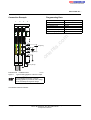
When another terminal is snapped next to this terminal, the bus coupler
configures the interface automatically.
If the next device is a terminal with a remote bus branch, the interface is
configured as a remote bus interface.
For every other device (e.g., I/O terminal) the interface is configured as a local
bus interface with diagnostics.
s.
co
Interface configuration (internal)
nt
Transmission Speed
500 kbps
IBS IL 24 BK-T/U
500 kbps
ne
IBS IL 24 BK-T/U-PAC
IBS IL 24 BK-T/U-2MBD-PAC
2 Mbps
IBS IL 24 BK-T/U-2MBD
2 Mbps
po
Common Data for 24 V Main Supply, Segment Supply, and Bus Coupler Supply
Connection
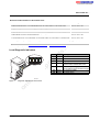
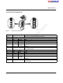
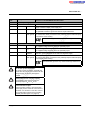
Through Inline connector; Terminal Point Assignment, see page 8
Spring-cage terminals
Recommended cable lengths
Continuation
Nominal value
Tolerance
Ripple
30 m, max.; routing cables through outdoor areas is not admissible
Via potential routing
UM/US are electrically isolated from the bus coupler supply UBK if they are
supplied separately. This is only ensured if two separate power supply units
are used.
24 V DC
-15% / +20% (according to EN 61131-2)
± 5%
19.2 V to 30 V
on
l
Permissible range
in
ec
Special demands on the voltage supply
om
Connection method
Provide an external fuse for the 24 V area
Each 24 V area must be protected externally. The power supply unit must be able to supply 4 times (400%) the nominal current of the
external fuse, to ensure that the fuse blows safely in the event of an error.
24 V Main Supply/24 V Segment Supply
Response in the event of voltage dips and interrupts
Voltages (main and segment supply) that are transferred from the bus
coupler to the potential jumpers follow the supply voltages without delay.
Current carrying capacity
8 A, max.
6291_en_02
PHOENIX CONTACT
3