1
IBS IL 24 BK-T/U ...
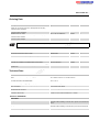
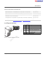
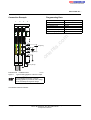
Terminal
Point
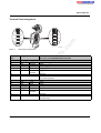
Connector 3
1.1, 2.1
1.2, 2.2
Assignment
1.3, 2.3
BK-GND
1.4, 2.4
FE
Remark/
Wire Color in the INTERBUS Standard Cable
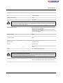
Bus Coupler Supply
Reserved
24 V DC
UBK
m
24 V bus coupler supply
Supply of the bus coupler power supply unit
BK-GND
GND of the bus coupler supply
This potential is reference ground for the bus coupler electronics.
Functional
Grounding of the bus coupler and therefore of the Inline station
earth ground The contacts are directly connected to the potential jumper and the FE spring
on the bottom of the housing.
co
Functional earth ground is only used to discharge interference.
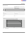
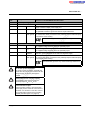
Connector 4 Power Connector
1.1, 2.1
24 V DC
US
GND
1.4, 2.4
FE
s.
1.3, 2.3
nt
24 V DC
po
ne
1.2, 2.2
24 V segment supply
The supplied voltage is directly led to the potential jumper.
24 V main supply
UM
The supplied voltage is directly led to the potential jumper.
Reference
The reference potential is directly led to the potential jumper and is, at the
potential
same time, ground reference for the main and segment supply.
Functional
Grounding of the bus coupler and therefore of the Inline station
earth ground The contacts are directly connected to the potential jumper and the FE spring
on the bottom of the housing.
om
Functional earth ground is only used to discharge interference.
in
ec
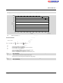
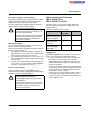
Do not mix up the connectors
on
l
Do not mix up the connectors, especially the
remote bus connectors and connectors for the
voltage supply, as this may damage the
terminal.
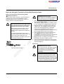
Observe the current carrying capacity
The maximum total current through the
potential jumpers UM and US is 8 A.
Ground the bus coupler
Connect the bus coupler to functional earth
ground (FE) via one of the FE connections of
connector 3 or connector 4. For this, connect
the corresponding contact with a grounding
terminal (see also Figure 6 on page 14).
6291_en_02
PHOENIX CONTACT
9