1
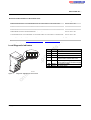
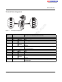
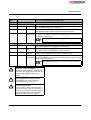
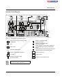
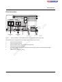
IBS IL 24 BK-T/U ...
Inline Bus Coupler for INTERBUS;
Remote Bus Connections Using Copper Cables
and Inline Connectors
4 x
Data Sheet
6291_en_02
m
AUTOMATIONWORX
© PHOENIX CONTACT - 09/2007
Description
s.
–
–
Remote bus connections using copper cables
Can supply an Inline station with all of the required
24 V voltages for low-level signals
Electrical isolation of the remote bus segments
Automatic configuration of the outgoing interface as
remote bus or local bus interface
Supports the connection of up to 15 terminals with
remote bus branch
Approved for the use in potentially explosive areas
(observe the notes on page 11)
nt
–
–
ne
The bus coupler connects an Inline station to the
INTERBUS remote bus and provides the supply voltages
for the connected devices.
co
Features
6 2 9 1 B 0 0 2
–
The end plate is supplied with the bus coupler. Place this
plate at the end of the Inline station. The end plate has no
electrical function. It protects the station from ESD pulses
and the user from dangerous voltage.
on
l
in
ec
om
po
–
This data sheet is only valid in association with the IB IL SYS PRO UM E user manual.
Make sure you always use the latest documentation.
It can be downloaded at www.download.phoenixcontact.com.
A conversion table is available on the Internet at
www.download.phoenixcontact.com/general/7000_en_00.pdf.
This data sheet is valid for the products listed on the following page:
IBS IL 24 BK-T/U ...
Ordering Data
Products
Description
Order No.
Pcs./Pkt.
IBS IL 24 BK-T/U-PAC
2861580
1
INTERBUS Inline bus coupler; without accessories;
transmission speed of 500 kbps
IBS IL 24 BK-T/U
2742094
1
INTERBUS Inline bus coupler;
complete with accessories (connectors, labeling fields and end plate);
transmission speed of 2 Mbps
IBS IL 24 BK-T/U-2MBD-PAC
2862000
1
INTERBUS Inline bus coupler; without accessories;
transmission speed of 2 Mbps
IBS IL 24 BK-T/U-2MBD
2855240
1
m
Type
INTERBUS Inline bus coupler;
complete with accessories (connectors, labeling fields and end plate);
transmission speed of 500 kbps
co
One of the listed connector sets is needed for the complete fitting of the IBS IL 24 BK-T/U and IBS IL 24 BK-T/U-2MBD terminals.
Type
Connector set for Inline bus coupler, copper
IB IL BK-PLSET
2727792
1
Connector set for Inline bus coupler, copper, with color print
IB IL BK-PLSET/CP
2860374
1
Type
Order No.
Pcs./Pkt.
IB IL SYS PRO UM E
2743048
1
AH EN IL EX ZONE 2
7217
1
Documentation
Description
po
"Configuring and Installing the INTERBUS Inline Product Range"
user manual
ne
nt
s.
Accessories
Description
in
ec
Technical Data
General Data
Pcs./Pkt.
om
"Inline Terminals for Use in Zone 2 Potentially Explosive Areas"
application note
Order No.
Housing dimensions (width x height x depth)
48.8 mm x 120 mm x 71.5 mm
Weight
142 g (without connector), 214 g (with connector)
Permissible temperature (operation)
-25°C to +55°C
Permissible temperature (storage/transport)
-25°C to +85 °C
10% to 95% according to DIN EN 61131-2
Permissible air pressure (operation/storage/transport)
70 kPa to 106 kPa (up to 3000 m above sea level)
on
l
Permissible humidity (operation/storage/transport)
Degree of protection
IP20 according to IEC 60529
Class of protection
Class 3 according to EN 61131-2, IEC 61131-2
Connection data for connectors
Connection type
Spring-cage terminals
Conductor cross-section
0.2 mm2 to 1.5 mm2 (solid or stranded), 24 - 16 AWG
Interfaces (INTERBUS)
Remote Bus
Incoming remote bus
Copper cable (RS-422), connected with Inline shield connector; supply
electrically isolated; shielding connected with a capacitor to functional earth
ground
Outgoing remote bus
Copper cable (RS-422), connected with Inline shield connector; supply
electrically isolated; shielding connected directly to functional earth ground
Recommended cable lengths
See INTERBUS System Data
6291_en_02
PHOENIX CONTACT
2
IBS IL 24 BK-T/U ...
Interfaces (INTERBUS) (Continued)
Branch/Local Bus
Connection
Through data routing
Level
5 V CMOS signal level
Number of Inline terminals that can be connected
Limitation through software
63, max.
Limitation through power supply unit
Maximum logic current consumption of the connected local bus modules:
Imax ≤ 2 A DC
Observe the current consumption of the modules
m
Observe the logic current consumption of each device when configuring an Inline station. It is specified in every terminal-specific data
sheet. The current consumption can differ depending on the individual terminal. The permissible number of devices that can be connected
therefore depends on the specific station structure.
Functional
When another terminal is snapped next to this terminal, the bus coupler
configures the interface automatically.
If the next device is a terminal with a remote bus branch, the interface is
configured as a remote bus interface.
For every other device (e.g., I/O terminal) the interface is configured as a local
bus interface with diagnostics.
s.
co
Interface configuration (internal)
nt
Transmission Speed
500 kbps
IBS IL 24 BK-T/U
500 kbps
ne
IBS IL 24 BK-T/U-PAC
IBS IL 24 BK-T/U-2MBD-PAC
2 Mbps
IBS IL 24 BK-T/U-2MBD
2 Mbps
po
Common Data for 24 V Main Supply, Segment Supply, and Bus Coupler Supply
Connection
Through Inline connector; Terminal Point Assignment, see page 8
Spring-cage terminals
Recommended cable lengths
Continuation
Nominal value
Tolerance
Ripple
30 m, max.; routing cables through outdoor areas is not admissible
Via potential routing
UM/US are electrically isolated from the bus coupler supply UBK if they are
supplied separately. This is only ensured if two separate power supply units
are used.
24 V DC
-15% / +20% (according to EN 61131-2)
± 5%
19.2 V to 30 V
on
l
Permissible range
in
ec
Special demands on the voltage supply
om
Connection method
Provide an external fuse for the 24 V area
Each 24 V area must be protected externally. The power supply unit must be able to supply 4 times (400%) the nominal current of the
external fuse, to ensure that the fuse blows safely in the event of an error.
24 V Main Supply/24 V Segment Supply
Response in the event of voltage dips and interrupts
Voltages (main and segment supply) that are transferred from the bus
coupler to the potential jumpers follow the supply voltages without delay.
Current carrying capacity
8 A, max.
6291_en_02
PHOENIX CONTACT
3
IBS IL 24 BK-T/U ...
24 V Bus Coupler Supply
Minimum current consumption at nominal voltage
0.10 A DC
(At no-load operation, i.e., incoming remote bus connected, no local bus
devices connected, bus inactive)
Maximum current consumption at nominal voltage
1.25 A DC
consisting of:
0.75 A DC for communications power
0.5 A DC for analog voltage supply
UL (7.5 V) and UANA (24 V) are generated from the 24 V bus coupler supply UBK.
7.5 V DC
Tolerance
± 5%
Ripple
± 1.5%
co
Nominal value
m
Communications and Analog Supply
Communications Power (Potential Jumpers)
2 A DC (observe derating)
Safety equipment
Electronic short-circuit protection
s.
Maximum output current
nt
Analog Supply (Potential Jumper)
Nominal value
24 V DC
-15% / +20%
ne
Tolerance
Ripple
± 5%
Maximum output current
0.5 A DC (observe derating)
Electrical short-circuit protection
po
Safety equipment
om
Derating of the Communications Power and the Analog Terminal Supply
- I/O Supply Current Carrying Capacity at the Bus Coupler of 8 A, Maximum
100
in
ec
90
80
70
50
on
l
P [%]
60
40
30
20
10
0
0
5
10
15
20
25
30
35
40
45
TA [°C]
P [%]
Current carrying capacity of the communications power (UL) and the analog supply (UANA) in %
TA [°C]
Ambient temperature in °C
6291_en_02
50
55
5560A012
PHOENIX CONTACT
4
IBS IL 24 BK-T/U ...
Derating of the Communications Power and the Analog Terminal Supply (Continued)
- I/O Supply Current Carrying Capacity at the Bus Coupler of 4 A, Maximum
100
90
80
70
50
40
m
P [%]
60
30
co
20
0
5
10
15
20
25
TA [°C]
30
35
40
45
nt
0
s.
10
Current carrying capacity of the communications power (UL) and the analog supply (UANA) in %
TA [°C]
Ambient temperature in °C
55
5560A013
ne
P [%]
50
po
Power Dissipation
Formula to Calculate the Power Dissipation of the Electronics
PEL = PBUS + PPERI
E L
= 1 .6 W
+ (1 .1 W
A
a
x ΣILn) + (0 .7 W
n = 1
b
x ΣILm )
om
P
A
m
= 1
Total power dissipation in the terminal
Power dissipation for bus operation without I/O load (constant)
Power dissipation with I/O connected
ILn
n
a
Current consumption of device n from the communications power
Index of the number of connected devices (n = 1 to a)
Number of connected devices (supplied with communications power)
n=1
ILm
n
b
b
S ILm
m=1
6291_en_02
Total current consumption of the devices from the 7.5 V communications power
(2 A, maximum)
on
l
a
S ILn
in
ec
Where
PEL
PBUS
PPERI
Current consumption of the device m from the analog supply
Index of the number of connected analog devices (n = 1 to b)
Number of the connected analog devices (supplied with analog voltage)
Total current consumption of the devices from the 24 V analog power
(0.5 A, maximum)
PHOENIX CONTACT
5
IBS IL 24 BK-T/U ...
Power Dissipation/Derating
Using the maximum currents 2 A (logic current) and 0.5 A (current for analog terminals) in the formula to calculate the power dissipation when the I/O is
connected results in the following:
PPERI = 2.2 W + 0.35 W = 2.55 W
2.55 W correspond to 100% current carrying capacity of the power supply unit in the derating curves on page 4.
Make sure that the indicated nominal current carrying capacity in the derating curves is not exceeded when the ambient temperature is above 40°C.
Corresponding to the formula, the total current carrying capacity of the connected I/O (PPERI) is relevant. If, for example, no current is drawn from the analog
supply, the percentage of current coming from the communications power may be increased.
Example:
Current carrying capacity of the I/O supply: 8 A
Nominal current carrying capacity of communications power and analog supply: 50% according to the diagram
ILLogic = 1 A, ILAnalog = 0.25 A
co
PPERI = 1.1 W + 0.175 W
m
Ambient temperature: 55 °C
PPERI = 1.275 W (corresponds to 50% of 2.55 W)
s.
Possible logic current if the analog supply is not loaded:
PPERI = 1.1 W/A x ILLogic+ 0 W
nt
PPERI / 1.1 W/A = ILLogic
ILLogic = 1.275 W / 1.1 W/A
ne
ILLogic = 1.159 A
Error Messages to the Higher-Level Control or Computer System
Yes, if the segment voltage US is not present
Safety Equipment
Polarity reversal (segment supply/main supply)
in
ec
Polarity reversal (bus coupler supply)
om
Surge voltage
(segment supply/main supply/bus coupler supply)
po
Peripheral fault
Input protective diodes (can be destroyed by permanent overload)
Pulse loads up to 1500 W are short circuited by the input protective diode.
Parallel diodes for protection against polarity reversal; in the event of an error
the high current through the diodes causes the preconnected fuse to blow.
Serial diode in the lead path of the power supply unit; in the event of an error
only a low current flows. In the event of an error, no fuse trips within the
external power supply unit.
on
l
If you want to protect the bus coupler supply UBK, use a 2 A medium blow fuse.
Electrical Isolation/Isolation of the Voltage Areas
Common Potentials
When providing the 24 V bus coupler
supply separately from the 24 V main
supply/24 V segment supply
Main and segment supply galvanically have the same potential. From the bus coupler onwards, common ground
is led through the potential jumper to the devices as the reference ground GND.
When providing the 24 V bus coupler
supply by jumpering the 24 V main
supply/24 V segment supply
Main supply, segment supply, 24 V analog supply, and 7.5 V communications power galvanically have the same
potential. From the bus coupler onwards, common ground is led through the potential jumper to the devices as
reference ground LGND for the communications power and analog supply and separately as reference ground
GND for the supply and segment level.
Bus coupler supply, analog supply, and 7.5 V communications power have the same potential. From the bus
coupler onwards, common ground is led through the potential jumper to the devices as the reference ground
LGND.
Separate Potentials
When providing the 24 V bus coupler
supply separately from the 24 V main
supply/24 V segment supply
When providing the 24 V bus coupler
supply by jumpering the 24 V main
supply/24 V segment supply
6291_en_02
The bus coupler supply is physically and therefore electrically isolated from the main and segment supply.
The interface supplies for the incoming and outgoing remote bus are electrically isolated from one another and
from the supplies.
The bus coupler has two interface supplies for the incoming and outgoing remote bus that are electrically isolated
from one another and from the primary/secondary supply.
The main supply is electrically isolated from the interface supplies.
PHOENIX CONTACT
6
IBS IL 24 BK-T/U ...
Electrical Isolation/Isolation of the Voltage Areas
Test Distance
Test Voltage
5 V supply incoming remote bus / 5 V supply outgoing remote bus
500 V AC, 50 Hz, 1 min
5 V supply incoming remote bus / 7.5 V communications power, 24 V analog supply, 24 V bus coupler supply
500 V AC, 50 Hz, 1 min
5 V supply incoming remote bus / 24 V main supply, 24 V segment supply
500 V AC, 50 Hz, 1 min
5 V supply incoming remote bus / functional earth ground
500 V AC, 50 Hz, 1 min
5 V supply outgoing remote bus / 7.5 V communications power, 24 V analog supply, 24 V bus coupler supply
500 V AC, 50 Hz, 1 min
5 V supply outgoing remote bus / 24 V main supply, 24 V segment supply
500 V AC, 50 Hz, 1 min
5 V supply outgoing remote bus / functional earth ground
500 V AC, 50 Hz, 1 min
500 V AC, 50 Hz, 1 min
500 V AC, 50 Hz, 1 min
24 V main supply, 24 V segment supply / functional earth ground
500 V AC, 50 Hz, 1 min
m
7.5 V communications power, 24 V analog supply, 24 V bus coupler supply / functional earth ground
7.5 V communications power, 24 V analog supply, 24 V bus coupler supply / 24 V main supply, 24 V segment supply
co
Approvals
For the latest approvals, please visit www.download.phoenixcontact.com or www.eshop.phoenixcontact.com.
nt
s.
Local Diagnostic Indicators
R D
R C
L D
U L
ne
B A
Des.
BA
RC
RD
LD
U S
U M
UL
US
UM
Meaning
Bus active
Remote bus cable check
Outgoing remote bus disabled
Local bus/remote bus branch
disconnected in isolation after error
Green 24 V bus coupler supply/7.5 V
communications power /interface supply
Green 24 V segment supply
Green 24 V main supply
in
ec
om
po
B K -T /U
Color
Green
Green
Yellow
Yellow
6 2 9 1 B 0 0 3
Diagnostic indicators of the terminal
on
l
Figure 1
6291_en_02
PHOENIX CONTACT
7
IBS IL 24 BK-T/U ...
Terminal Point Assignment
1
2
1 .1
1
1
2 .1
1 .1
1
1
2 .1
1 .2
2
2
2 .2
1 .2
2
2
2 .2
1 .3
3
3
2 .3
1 .3
3
3
2 .3
1 .4
4
4
2 .4
1 .4
4
4
2 .4
6 2 9 1 A 0 0 6
2.3
1.4, 2.4
6291_en_02
nt
Not used
Shield potential is connected with a capacitor to functional earth ground (FE)
of the potential jumper.
Outgoing Remote Bus
/DO2
Send
DO2
Send
/DI2
Receive
DI2
Receive
R-GND
Reference
potential
Green
Yellow
Pink
Gray
Brown
Shield
Not used
Shield potential is connected directly to functional earth ground (FE) of the
potential jumper.
on
l
2.3
1.4, 2.4
Green
Yellow
Pink
Gray
Brown
ne
Incoming Remote Bus
/DO1
Receive
DO1
Receive
/DI1
Send
DI1
Send
F-GND
Reference
potential
Shield
Connector 2
1.1
2.1
1.2
2.2
1.3
Remark/
Wire Color in the INTERBUS Standard Cable
po
Assignment
om
Terminal
Point
Connector 1
1.1
2.1
1.2
2.2
1.3
s.
Terminal point assignment
in
ec
Figure 2
m
2
co
1
PHOENIX CONTACT
8
IBS IL 24 BK-T/U ...
Terminal
Point
Connector 3
1.1, 2.1
1.2, 2.2
Assignment
1.3, 2.3
BK-GND
1.4, 2.4
FE
Remark/
Wire Color in the INTERBUS Standard Cable
Bus Coupler Supply
Reserved
24 V DC
UBK
m
24 V bus coupler supply
Supply of the bus coupler power supply unit
BK-GND
GND of the bus coupler supply
This potential is reference ground for the bus coupler electronics.
Functional
Grounding of the bus coupler and therefore of the Inline station
earth ground The contacts are directly connected to the potential jumper and the FE spring
on the bottom of the housing.
co
Functional earth ground is only used to discharge interference.
Connector 4 Power Connector
1.1, 2.1
24 V DC
US
GND
1.4, 2.4
FE
s.
1.3, 2.3
nt
24 V DC
po
ne
1.2, 2.2
24 V segment supply
The supplied voltage is directly led to the potential jumper.
24 V main supply
UM
The supplied voltage is directly led to the potential jumper.
Reference
The reference potential is directly led to the potential jumper and is, at the
potential
same time, ground reference for the main and segment supply.
Functional
Grounding of the bus coupler and therefore of the Inline station
earth ground The contacts are directly connected to the potential jumper and the FE spring
on the bottom of the housing.
om
Functional earth ground is only used to discharge interference.
in
ec
Do not mix up the connectors
on
l
Do not mix up the connectors, especially the
remote bus connectors and connectors for the
voltage supply, as this may damage the
terminal.
Observe the current carrying capacity
The maximum total current through the
potential jumpers UM and US is 8 A.
Ground the bus coupler
Connect the bus coupler to functional earth
ground (FE) via one of the FE connections of
connector 3 or connector 4. For this, connect
the corresponding contact with a grounding
terminal (see also Figure 6 on page 14).
6291_en_02
PHOENIX CONTACT
9
IBS IL 24 BK-T/U ...
24 V Segment Supply / 24 V Main Supply
The segment supply and main supply must have the same
reference potential. Therefore, an electrically isolated
voltage area on the I/O side cannot be created.
Notes on Using the Terminals
IBS IL 24 BK-T and
IBS IL 24 BK-T/U (-PAC):
The IBS IL 24 BK-T/U (-PAC) bus coupler replaces the
IBS IL 24 BK-T bus coupler in the catalog, which was
supplied until now.
The main supply and the segment supply are protected
against polarity reversal and surge voltage.
Ensure short-circuit protection
Differences between the bus couplers
co
1
04dec
12dec
04dec
04dec
Please use the IBS IL 24 BK-T/U terminal for new
configurations.
in
ec
24 V Bus Coupler Supply
om
po
ne
You can supply/generate the segment supply at the bus
coupler or one of the supply terminals.
There are several ways of providing the segment voltage at
the bus coupler (connector 4):
1. The segment voltage can be supplied separately at
terminal points 1.1 (or 2.1) and 1.3 (or 2.3) (GND) of the
power connector (see Figure 6 on page 14).
2. You can jumper the connections 1.1 (or 2.1) and 1.2 (or
2.2) to ensure that the segment circuit is supplied from
the main circuit.
3. A switch can be inserted between terminal points 1.1
(or 2.1) and 1.2 (or 2.2) to create a switched segment
circuit (e.g., an emergency stop circuit).
s.
24 V Segment Supply
Number of terminals
with remote bus branch
that can be aligned
ID code with remote
bus branch being
connected
ID code without remote
bus branch being
connected
IBS IL 24 BK-T
nt
The user must provide short-circuit protection.
The rating of the preconnected fuse must be
such that the maximum permissible load
current is not exceeded.
IBS IL 24 BKT/U (-PAC)
15
m
The main supply and segment supply do not
have short-circuit protection.
The bus coupler supply is protected against polarity
reversal and surge voltage. These protective elements are
only used to protect the power supply unit.
on
l
Ensure short-circuit protection
The bus coupler supply does not have shortcircuit protection.
If you plan to replace an IBS IL 24 BK-T terminal in your
system, you must check the replacement options:
– If, until now, the IBS IL 24 BK-T bus coupler has not
been used in conjunction with an IB IL 24 RB-T
terminal with remote bus branch, the terminal can be
replaced with the IBS IL 24 BK-T/U (-PAC) terminal
without any problems.
– If, until now, the IBS IL 24 BK-T bus coupler has been
used in conjunction with an IB IL 24 RB-T terminal with
remote bus branch, you should replace the terminal
with the IBS IL 24 BK-T terminal.
If in this case you were to replace the IBS IL 24 BK-T
bus terminal with the IBS IL 24 BK-T/U (-PAC) bus
coupler, the system would need to be reconfigured due
to the modified ID code.
The user must provide short-circuit protection.
The rating of the preconnected fuse must be
such that the maximum permissible load
current is not exceeded.
6291_en_02
PHOENIX CONTACT
10
IBS IL 24 BK-T/U ...
Notes on Using the Terminal in Potentially Explosive Areas
Approval According to EC Directive 94/9 (ATEX)
II 3G Ex nAC IIC T4 X
WARNING: Explosion hazard
This Inline bus coupler conforms to the requirements of
protection type "n" and can be installed in a zone 2
potentially explosive area. This Inline bus coupler is a
category 3G item of electrical equipment.
Before startup, ensure that the following
points and instructions are observed.
4.
5.
Check the labeling on the Inline terminal and
the packaging (see Figure 3).
6.
ne
For a list of terminals approved for zone 2
potentially explosive areas, please refer to the
AH EN IL EX ZONE 2 application note.
po
7.
IBx IL xx xx x
Order-No.: xxxxxxx
Module-ID: xx HW/FW XX/INTERBUS
UL
xx
LISTED
31ZN
Proc. Ctrl. Eqpt. For Haz. Locs.
Cl. I, Zn. 2, AEx nC IIC T5
Cl. I, Zn. 2, Ex nC IIC T5
Cl. I, Div. 2, Grp. A,B,C,D T5
5561C001
Typical labeling of terminals for use in
potentially explosive areas
on
l
in
ec
Figure 3
GL
om
II 3G Ex nAC IIC T4 X
Potential routing 4 A maximum
for use in Ex areas
6291_en_02
m
Before using an Inline terminal in a zone 2
potentially explosive area, check that the
terminal has been approved for installation in
this area.
co
3.
s.
2.
WARNING: Explosion hazard
Only Inline terminals that are approved for
use in potentially explosive areas may be
snapped next to this Inline bus coupler.
When working on the Inline bus coupler, always
disconnect the supply voltage.
The Inline bus coupler must only be installed, started
up, and maintained by qualified specialist personnel.
Install the Inline bus coupler in a control cabinet or
metal housing. The minimum requirement for both
items is IP54 protection according to EN 60529.
The Inline bus coupler must not be subject to
mechanical strain or thermal loads, which exceed the
limits specified in the product documentation.
The Inline bus coupler must not be repaired by the
user. Repairs may only be carried out by the
manufacturer. The Inline bus coupler is to be replaced
by an approved bus coupler of the same type.
During operation, only category 3G equipment may be
connected to Inline bus couplers in zone 2.
Observe all applicable standards and national safety
and accident prevention regulations for installing and
operating equipment.
nt
1.
Restrictions
WARNING: Explosion hazard
When using terminals in potentially explosive
areas, observe the technical data and limit
values specified in the corresponding
documentation (user manual, data sheet,
package slip).
WARNING: Explosion hazard
Restrictions regarding the Inline system
The maximum permissible current flowing
through the potential jumpers UM and US (total
current) is limited to 4 A when using the Inline
bus coupler in potentially explosive areas.
PHOENIX CONTACT
11
IBS IL 24 BK-T/U ...
Internal Circuit Diagram
BA
RD
RC
LD
UL
Local bus
US
6
OPC
2
2
UL
UM
Reset
Circuit
5V
/
RS-422
Interface
RS-422
Interface
24 V
/
/
1
RS-422
Interface
24 V
24 V
/
s.
RS-422
Interface
7,5 V
7,5 V
Interface
Autoconfig.
co
5V
2
ne
po
Internal wiring of the terminal points
Reference potential R-GND
(outgoing interface)
LED
3
Reference potential BK-GND
(bus coupler supply)
om
2
Optocoupler
Electrically isolated area
on
l
Supply unit with electrical isolation
Converter
1
6291B007
Protocol chip (bus logic including voltage
conditioning)
in
ec
OPC
+24 V (UM)
3
2
Figure 4
+24 V (US)
nt
1
m
5V
Reference potential F-GND
(incoming interface)
1
Shield potential; connected with a capacitor to
functional earth ground (FE) of the potential
jumper
2
Shield potential; connected directly to functional
earth ground (FE) of the potential jumper
R S -4 2 2
In te rfa c e
/
R e s e t
C ir c u it
In te rfa c e
A u to c o n fig .
Interface component
Voltage monitor
Switchover remote bus/local bus
Other symbols used are explained in the
IB IL SYS PRO UM E user manual.
6291_en_02
PHOENIX CONTACT
12
IBS IL 24 BK-T/U ...
Electrical Isolation
L o c a l b u s
U L+
U AN A
U L-
O P C
5 V
7 ,5 V
A
B
5 V
E
2 4 V
5 V
2 4 V
F
2
+ 2 4 V (U
3
1
2
U
(U
)
L
U
B K
/ U
A N A
)
M
/ U
S
5 5 2 0 D 0 2 8
Electrical isolation of the individual function areas (separate power supply units)
po
Figure 5
M
s.
IN T E R B U S
O U T
nt
IN T E R B U S
IN
D
ne
C
)
S
co
1
+ 2 4 V (U
m
2 4 V
7 ,5 V
Potential areas when using separate power supply units to supply UBK and UM/US:
om
on
l
6
Area of incoming remote bus
Area of outgoing remote bus
Area of functional earth using a capacitor (FE capacitive)
Area of functional earth ground (FE)
Area of bus coupler supply UBK from which the communications power UL and analog terminal supply
UANA are generated
Area of the I/O voltages UM and US
in
ec
1
2
3
4
5
6291_en_02
PHOENIX CONTACT
13
IBS IL 24 BK-T/U ...
Connection Example
1
2
BA
RD
RC
LD
3
Programming Data
ID code
Length code
Process data channel
Input address area
Output address area
Parameter channel (PCP)
Register length (bus)
4
US
UL
04hex (04dec)
00hex
0 bits
0 bytes
0 bytes
0 bytes
0 bytes
UM
2
1
2
1
2
1
2
1
11
11
11
1
2
22
22
22
2
3
33
33
33
3
co
1
m
BK-T/U
- U (24 V)
nt
S
+
-
44
44
4
+
INTERBUS IN
(24 V)
INTERBUS OUT
6291B004
Typical cable connection at the bus coupler
on
l
Figure 6
BK
in
ec
-U
om
po
44
ne
UM (24 V)
4
s.
+
To minimize heat generation, use both
adjacent contacts to provide the main voltage
and to provide/tap the segment voltage.
© PHOENIX CONTACT 09/2007
6291_en_02
PHOENIX CONTACT GmbH & Co. KG • 32823 Blomberg • Germany
Phone: +49-(0) 5235-3-00 • Fax: +49-(0) 5235-3-4 12 00
www.phoenixcontact.com
14