1
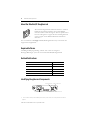
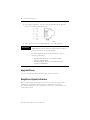
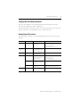
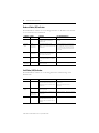
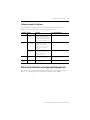
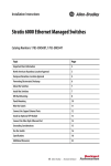
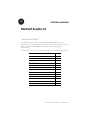
Installation Instructions
EtherNet/IP Daughtercard
Catalog Number 1788-ENBT
Use this document as a guide to install the EtherNet/IP daughtercard. This
document covers only the hardware installation; refer to the FlexLogix System User
Manual, publication 1794-UM001, for information about configuring the
daughtercard.
This table lists the contents of the document and where to find specific information.
For information about
See page
Important User Information
2
About the EtherNet/IP Daughtercard
4
Required Software
4
Related Publications
4
Identifying Daughtercard Components
4
Install the Daughtercard
5
Connect the Daughtercard to the Network
5
Apply Host Power
6
Daughtercard System Performance
6
Interpret the LED Status Indicators
7
Where to Find Information on Configuring the Daughtercard
9
Hazardous Location Information
10
Specifications
11
Publication 1788-IN054A-EN-P - September 2002
2
EtherNet/IP Daughtercard
Important User Information
Because of the variety of uses for the products described in this publication, those
responsible for the application and use of these products must satisfy themselves that all
necessary steps have been taken to assure that each application and use meets all
performance and safety requirements, including any applicable laws, regulations, codes
and standards. In no event will Rockwell Automation, Inc. be responsible or liable for
indirect or consequential damage resulting from the use or application of these
products.
Any illustrations, charts, sample programs, and layout examples shown in this
publication are intended solely for purposes of example. Since there are many variables
and requirements associated with any particular installation, Rockwell Automation does
not assume responsibility or liability (to include intellectual property liability) for actual
use based upon the examples shown in this publication.
Allen-Bradley publication SGI-1.1, Safety Guidelines for the Application, Installation and
Maintenance of Solid-State Control (available from your local Rockwell Automation
office), describes some important differences between solid-state equipment and
electromechanical devices that should be taken into consideration when applying
products such as those described in this publication.
Reproduction of the contents of this copyrighted publication, in whole or part, without
written permission of Rockwell Automation, is prohibited.
Throughout this publication, notes may be used to make you aware of safety
considerations. The following annotations and their accompanying statements help you
to identify a potential hazard, avoid a potential hazard, and recognize the consequences
of a potential hazard:
WARNING
Identifies information about practices or circumstances that can
cause an explosion in a hazardous environment, which may lead
to personal injury or death, property damage, or economic loss.
!
ATTENTION
Identifies information about practices or circumstances that can
lead to personal injury or death, property damage, or economic
loss.
!
IMPORTANT
Identifies information that is critical for successful application and
understanding of the product.
Publication 1788-IN054A-EN-P - September 2002
EtherNet/IP Daughtercard
ATTENTION
!
3
Environment and Enclosure
This equipment is intended for use in a Pollution Degree 2
industrial environment, in overvoltage Category II applications
(as defined in IEC publication 60664-1), at altitudes up to 2000
meters without derating.
This equipment is considered Group 1, Class A industrial
equipment according to IEC/CISPR Publication 11. Without
appropriate precautions, there may be potential difficulties
ensuring electromagnetic compatibility in other environments
due to conducted as well as radiated disturbance.
This equipment is supplied as “open type” equipment. It must
be mounted within an enclosure that is suitably designed for
those specific environmental conditions that will be present
and appropriately designed to prevent personal injury resulting
from accessibility to live parts. The interior of the enclosure
must be accessible only by the use of a tool. Subsequent
sections of this publication may contain additional information
regarding specific enclosure type ratings that are required to
comply with certain product safety certifications.
See NEMA Standards publication 250 and IEC publication
60529, as applicable, for explanations of the degrees of
protection provided by different types of enclosure. Also, see
the appropriate sections in this publication, as well as the
Allen-Bradley publication 1770-4.1 (“Industrial Automation
Wiring and Grounding Guidelines”), for additional installation
requirements pertaining to this equipment.
ATTENTION
!
Preventing Electrostatic Discharge
This equipment is sensitive to electrostatic discharge, which
can cause internal damage and affect normal operation.
Follow these guidelines when you handle this equipment:
•
•
•
•
•
•
Touch a grounded object to discharge potential static.
Wear an approved grounding wriststrap.
Do not touch connectors or pins on component boards.
Do not touch circuit components inside the equipment.
If available, use a static-safe workstation.
When not in use, store the equipment in appropriate
static-safe packaging.
Publication 1788-IN054A-EN-P - September 2002
4
EtherNet/IP Daughtercard
About the EtherNet/IP Daughtercard
31447-M
The network daughtercard architecture defines a common
hardware and software interface that several different
network interface cards will support. This lets products that
have been designed to support the network daughtercard
option support several different Rockwell Automation
networks.
You can install the 1788-ENBT EtherNet/IP daughtercard in any host device that
supports the daughtercard.(1)
Required Software
Use RSLogix 5000 programming software V11 or later to configure a
FlexLogix/DriveLogix system for use with the EtherNet/IP daughtercard.
Related Publications
Publication Title
Publication Number
EtherNet/IP System Overview
ENET-SO001
EtherNet/IP Media Planning and Installation Manual
ENET-IN001
EtherNet/IP Performance and Application Guide
ENET-AP001
FlexLogix System User Manual
1794-UM001
EtherNet/IP Daughtercard User Manual
1788-UM054
Identifying Daughtercard Components
module status LED
M
S
network status LED
N
S
E
N
E
T
LNK U%
RJ45 cable connector
(1)
link status LED
utilization percent LED
The host device must provide suitable power source per the restrictions in the specifications table on
page 11.
Publication 1788-IN054A-EN-P - September 2002
EtherNet/IP Daughtercard
5
Install the Daughtercard
Due to wide variation in available host devices, we cannot provide specific installation
instructions in this document. For instructions on how to install the daughtercard in a
host device, refer to the user manual for the particular host device.
IMPORTANT
WARNING
Do not insert or remove the daughtercard while the host is under
power. The daughtercard is not designed to be inserted or
removed while the host is powered.
Inserting or removing the module while host power is on may
cause an electrical arc. This could cause an explosion in hazardous location installations.
!
Connect the Daughtercard to the Network
After you have installed the daughtercard, you can connect it to the network
via the RJ45 connector.
WARNING
!
If you insert or remove the card while host power is on OR
if you connect or disconnect the Ethernet cable with power
applied to this module or any device on the network, an
electrical arc can occur.
Either could cause an explosion in hazardous location
installations.
Be sure that power is removed or the area is nonhazardous
before proceeding.
Publication 1788-IN054A-EN-P - September 2002
6
EtherNet/IP Daughtercard
1. Use an RJ45 connector to connect to the EtherNet/IP network. Wire the
connector according to this illustration:
8 ------ NC
7 ------ NC
6 ------ RD5 ------ NC
4 ------ NC
3 ------ RD+
2 ------ TD1 ------ TD+
2. Attach the connector to the EtherNet/IP port on the daughtercard.
IMPORTANT
We recommend connecting the module to the network via a
100MB Ethernet switch, which will reduce collisions and lost
packets and increase network bandwidth.
For detailed EtherNet/IP connection information, see the
following publications:
–
–
EtherNet/IP Performance and Application Guide,
publication ENET-AP001
EtherNet/IP Media Planning and Installation Guide,
publication ENET-IN001
Apply Host Power
To power the EtherNet/IP daughtercard, apply power to the host.
Daughtercard System Performance
Due to wide variation in available host devices, we cannot provide specific
performance capabilities in this document. For information concerning
host/daughtercard performance characteristics, refer to the user manual for the
particular host device.
Publication 1788-IN054A-EN-P - September 2002
EtherNet/IP Daughtercard
7
Interpret the LED Status Indicators
The four status indicators on the daughtercard provide information about the
network, the daughtercard, and its connections.
The following tables outline the possible states, explain what each state means, and
indicate what action you should take, if any, to correct that state.
Module Status (MS) Indicator
This LED indicates whether or not the daughtercard has power and is operating
properly.
Condition
Status
Indicates
Recommended Action
off
no power
The daughtercard does not
have power.
Check the host power supply.
Verify that the daughtercard is firmly
seated in the host’s slot.
Replace daughtercard and/or host.
flashing
green
standby
The daughtercard does not
have an IP address and is
operating in BOOTP mode.
Verify that the BOOTP server is running.
green
OK
The daughtercard is
operating correctly.
Normal operation. No action required.
red
held in reset
The host is holding the
daughtercard in reset or
the host is faulted.
Verify that the daughtercard is firmly
seated in the host’s slot.
Clear the host’s fault.
Replace daughtercard and/or host.
self-test
The daughtercard is
performing its power-up
self-test.
Normal operation during powerup.
major fault
An unrecoverable fault has
occurred.
Cycle power to the host.
Replace the daughtercard and/or host.
flashing red
updating firmware The daughtercard firmware
is being updated.
Normal operation during firmware
update. No action required.
Publication 1788-IN054A-EN-P - September 2002
8
EtherNet/IP Daughtercard
Network Status (NS) Indicator
This LED indicates whether or not the daughtercard has an IP address and whether
or not connections are established.
Condition
Status
Indicates
Recommended Action
off
not initialized
The daughtercard does not have an
IP address and is operating in
BOOTP mode.
Verify that the BOOTP server is
running.
flashing
green
no CIP
connections
established
The daughtercard has an IP
address, but no CIP connections are
established.
Normal operation if no connections
are configured. No action required.
If connections are configured, check
connection originator for connection
error code.
green
CIP connections
established
The daughtercard has an IP address
and CIP connections (Class 1 or
Class 3) are established.
Normal operation. No action required.
red
duplicate IP
address
The daughtercard has detected that
the assigned IP address is already
in use.
Verify that all IP addresses are unique.
flashing
red/green
self-test
The daughtercard is performing its
power-up self-test.
Normal operation during powerup.
Link Status (LNK) Indicator
This LED indicates whether or not the daughtercard is communicating on the
Ethernet link.
Condition
Status
Indicates
Recommended Action
off
no link
The daughtercard is not connected
to a powered Ethernet device. The
daughercard cannot communicate
on Ethernet.
Verify that all Ethernet cables are
connected.
Verify that Ethernet switch is
powered.
flashing
green
self-test
The daughtercard is performing its
power-up self-test.
Normal operation during powerup.
data
transmission
and reception
The daughtercard is communicating
on Ethernet.
Normal operation. No action required.
link okay
The daughtercard is connected to a
powered Ethernet device. The
daughtercard can communicate on
Ethernet.
Normal operation. No action required.
green
Publication 1788-IN054A-EN-P - September 2002
EtherNet/IP Daughtercard
9
Utilization Percent (U%) Indicator
This LED indicates utilization percent of the daughtercard only and does not
address the system performance of the daughtercard plus host.
Condition
Status
Indicates
Recommended Action
off
less than 80%
utilization
The I/O packet rate to/from this
daughtercard is less than 80% of
the available packet rate and less
than 80% of the 32 available I/O
connections are currently in use.
Normal operation. No action required.
flashing
green
80% packet
rate reached
The I/O packet rate to/from this
daughtercard is at least 80% of the
available packet rate (4000
packets/sec). That is, the I/O
packet rate is at least 3200
packets/sec.
Normal operation. No action required.
80%
connections in
use
At least 80% of the 32 available
connections are currently in use.
That is, from 26 to 31 I/O
connections are in use.
Normal operation. No action required.
green
all connections
in use
All 32 of the daughtercard’s I/O
connections are currently in use.
Normal operation when all 32 I/O
connections are in use.
flashing
red/green
self-test
The daughtercard is performing its
power-up self-test.
Normal operation during powerup.
Where to Find Information on Configuring the Daughtercard
Now that you have installed your EtherNet/IP daughtercard, you must configure it.
Refer to your FlexLogix System User Manual, publication 1794-UM001.
Publication 1788-IN054A-EN-P - September 2002
10
EtherNet/IP Daughtercard
Hazardous Location Information
The following information applies when
operating this equipment in hazardous
locations:
Informations sur l’utilisation de cet équipement
en environnements dangereux :
Products marked “CL I, DIV 2, GP A, B, C, D” are
suitable for use in Class I Division 2 Groups A, B, C,
D, Hazardous Locations and nonhazardous locations
only. Each product is supplied with markings on the
rating nameplate indicating the hazardous location
temperature code. When combining products within
a system, the most adverse temperature code (lowest
“T” number) may be used to help determine the
overall temperature code of the system.
Combinations of equipment in your system are
subject to investigation by the local Authority Having
Jurisdiction at the time of installation.
Les produits marqués "CL I, DIV 2, GP A, B, C, D" ne
conviennent qu’à une utilisation en environnements
de Classe I Division 2 Groupes A, B, C, D dangereux
et non dangereux. Chaque produit est livré avec des
marquages sur sa plaque d’identification qui
indiquent le code de température pour les
environnements dangereux. Lorsque plusieurs
produits sont combinés dans un système, le code de
température le plus défavorable (code de
température le plus faible) peut être utilisé pour
déterminer le code de température global du
système. Les combinaisons d’équipements dans le
système sont sujettes à inspection par les autorités
locales qualifiées au moment de l’installation.
WARNING
!
EXPLOSION HAZARD
• Do not disconnect
equipment unless
power has been
removed or the area is
known to be
nonhazardous.
• Do not disconnect
connections to this
equipment unless
power has been
removed or the area is
known to be
nonhazardous. Secure
any external
connections that mate
to this equipment by
using screws, sliding
latches, threaded
connectors, or other
means provided with
this product.
• Substitution of
components may impair
suitability for Class I,
Division 2.
• If this product contains
batteries, they must
only be changed in an
area known to be
nonhazardous.
Publication 1788-IN054A-EN-P - September 2002
AVERTISSEMENT
!
RISQUE D’EXPLOSION
• Couper le courant ou
s’assurer que
l’environnement est
classé non dangereux
avant de débrancher
l'équipement.
• Couper le courant ou
s'assurer que
l’environnement est
classé non dangereux
avant de débrancher les
connecteurs. Fixer tous
les connecteurs
externes reliés à cet
équipement à l'aide de
vis, loquets coulissants,
connecteurs filetés ou
autres moyens fournis
avec ce produit.
• La substitution de
composants peut rendre
cet équipement
inadapté à une
utilisation en
environnement de
Classe I, Division 2.
• S’assurer que
l’environnement est
classé non dangereux
avant de changer les
piles.
EtherNet/IP Daughtercard
11
Specifications
Characteristic
Value
Power Requirements
5V dc @ 465mA(1)
Power Consumption
5 V dc, 2.33W
Thermal Dissipation 8.0 BTU/hr
Isolation Voltage
Tested to withstand 500V ac for 60 seconds
Ethernet Conductors
Wiring 802.3 compliant - twisted pair
Category 2(2)
Ethernet Connector
RJ45 Category 5
Emissions
CISPR 11: Group 1, Class A (with appropriate enclosure)
ESD Immunity
IEC 61000-4-2:
6kV contact discharges
8kV air discharges
Radiated RF Immunity
IEC 61000-4-3:
10V/m with 1kHz sine-wave 80%AM from 30MHz to 2000MHz
10V/m with 200Hz 50% Pulse 100%AM at 900Mhz
EFT/B Immunity
IEC 61000-4-4:
±2kV at 5kHz on communications ports
Surge Transient Immunity
IEC 61000-4-5:
±2kV line-earth (CM) on communications ports
Conducted RF Immunity
IEC 61000-4-6:
10Vrms with 1kHz sine-wave 80%AM from 150kHz to 80MHz
Enclosure Type Rating
None (open-style)
Operating Temperature
IEC 60068-2-1 (Test Ad, Operating Cold),
IEC 60068-2-2 (Test Bd, Operating Dry Heat),
IEC 60068-2-14 (Test Nb, Operating Thermal Shock):
This product is suitable for application in equipment that is rated 0 to 60oC
(32 to 140oF) maximum. It is acceptable for the ambient slot temperature
immediately surrounding this product to reach 85oC (185oF) maximum.
Storage Temperature
IEC 60068-2-1 (Test Ab, Un-packaged Non-operating Cold),
IEC 60068-2-2 (Test Bb, Un-packaged Non-operating Dry Heat),
IEC 60068-2-14 (Test Na, Un-packaged Non-operating Thermal Shock):
–40 to 85°C (–40 to 185°F)
Relative Humidity
IEC 60068-2-30 (Test Db, Un-packaged Non-operating Damp Heat):
5 to 95% non-condensing
Shock
IEC60068-2-27 (Test Ea, Unpackaged Shock):
Operating 30g
Non-operating 50g
Publication 1788-IN054A-EN-P - September 2002
Vibration
IEC60068-2-6 (Test Fc, Operating):
5g @ 10-500Hz
Weight
0.1 kg (0.2 lb.)
Certifications:
(when product is marked)
c-UR-us
(1)
(2)
(3)
UL Recognized Component Industrial Control Equipment for
Class I, Division 2 Group A,B,C,D Hazardous
Locations, certified for US and Canada.
European Union 89/336/EEC EMC Directive, compliant with:
CE(3)
EN 61000-6-4; Industrial Emissions
EN 50082-2; Industrial Immunity
EN 61326; Meas./Control/Lab., Industrial
Requirements
EN 61000-6-2; Industrial Immunity
Australian Radiocommunications Act, compliant with:
C-Tick(3)
AS/NZS 2064; Industrial Emissions
EtherNet/IP ODVA conformance tested to EtherNet/IP specifications.
To comply with UL restrictions, this equipment must be powered from a source compliant with the following: Class 2 or
Limited Voltage/Current, as defined in UL 508 Seventeenth Edition Section 32.
For information on conductor routing refer to publications 1770-4.1, Industrial Automation Wiring and Grounding Guidelines,
and ENET-IN001, EtherNet/IP Media Planning and Installation Manual.
See the Product Certification link at www.ab.com for Declarations of Conformity, Certificates, and other certification details.
Allen-Bradley, FlexLogix, and DriveLogix are trademarks of Rockwell Automation, Inc.
RSLogix is a trademark of Rockwell Software, Inc.
Publication 1788-IN054A-EN-P - September 2002
PN 957678-55
© 2002 Rockwell Automation. Printed in the U.S.A.