1
303 Installing Models with Internal (Attached) Bypass Switches
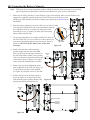
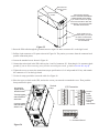
1. The internal bypass switch is attached to the back of the UPS. Remove the screws in the lower part of the
bypass switch’s back panel to remove the panel. Then, remove knock-outs in the bottom of the bypass
switch for AC Line Input and AC to UPS-protected equipment (loads).
2. Install the conduit adapters. You must run the AC input service conductor and the AC Output through
separate conduit adapters and separate conduit. UPS output circuits shall be installed in dedicated conduit
systems and not shared with other electrical circuits.
CAUTION
To prevent electrical shock or damage to your equipment, make sure the AC input is OFF at the service
panel and the bypass and AC Disconnect switches are OFF before you connect any wires to the bypass
switch terminal strip.
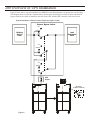
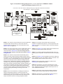
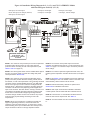
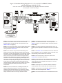
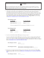
3. Find the terminal strip inside the bypass switch. Using the label inside the switch and the appropriate
Installation Wiring diagram on the following pages (Figure 15, 16, or 17), make the terminal strip
connections, tightening all connections securely. Use copper wire, and use the appropriate wire size for the
current draw. Figure 14 below shows a sample terminal strip label. Torque specifications for these
connections are 10.6-12.3 inch-pounds (1.2-1.4 N-m).
Important:
Make all terminal strip connections exactly as they are shown on the Installation
Wiring Diagram to ensure correct phase relationships, and follow the grounding
guidelines in the Diagram. Good ground connections are necessary to reduce electrical
noise and make operation of the UPS and the loads safe.
Internal Bypass Switch Terminal Label
X3 X2
X1
L1
L1 L1
AC TO UPS
PROTECTED
LOADS
L2
L2 L2
N
N N
LINE AC INPUT
REFER TO WIRING DIAGRAMS IN THE INSTALLATION MANUAL.
!
USE COPPER CONDUCTORS ONLY.
LAB-1919
Figure 14
4. If your UPS does not have a separate battery cabinet (external batteries), go to Section 500 to set UPS
parameters and perform the phase check.
If your model has external batteries, go to Section 400, Installing the Batteries and DC wiring. Then, go to
Section 500.
20