1
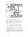
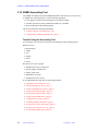
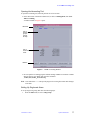
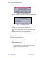
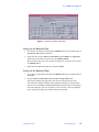
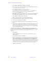
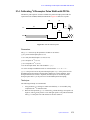
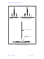
Chapter 21. Calibration Tests and Shimming
Sensitivity as Function of 15N Decoupling Power in Presence of 13C Decoupling
Experiment: A single-scan experiment with a 90° observe pulse is measured with no
decoupling; and 15N decoupling with power levels for decoupling varied from 1 dB up to
the user-supplied limit less 6 dB. 13C decoupling at the user-supplied limit less 3 dB is
applied in all experiments.
Signal-to-noise of the water is measured at each power level and the average of all these is
stored along with the corresponding effective “loss” of signal-to-noise ratio relative to the
no-decoupling results (expressed in % loss). The average signal-to-noise level and
corresponding power levels are stored in a text file as the experiment proceeds. At the end,
a histogram of the results is displayed and (optionally) plotted
A fixed region of noise is plotted for each power level to permit visual comparison. Plotted
data also has printouts of signal-to-noise measurements and line widths for each spectrum.
The test is performed separately for cw, hardware modulator-based waltz-16 and waveform
generator-based waltz-16 modulation. Results are stored in the SN_13Ccw_15Ndec_*_c
history files.
Purpose: This tests permits a direct measurement of noise arising from simultaneous 13C
and 15N decoupling as a function of power, for different modulation schemes.
13
C Decoupling using Phase Modulation
13
C power level is reduced 20 dB from the hard-pulse level, limited by the user-supplied
upper limit, and the 13C decoupling efficiency is determined for the following phasemodulated, constant-amplitude broadband decoupling sequences using the built-in channel
2 hardware modulator (not the waveform generator):
The 13C decoupling frequency is varied over a range of ± 80 ppm in a series of single-scan,
proton-observe experiments. Only the 13C-bound protons are shown in the expanded
spectrum, which is plotted with spectra side-by-side in absolute intensity mode to illustrate
decoupling efficiency.
Purpose This tests the hardware modulator under the user-supplied upper limit for
decoupling.
13
C Decoupling using Adiabatic Decoupling
The decoupling profile experiment is repeated using the (optional) channel 2 waveform
generator with two adiabatic decoupling schemes (STUD and WURST) under usersupplied upper limit on power. The waveforms are created automatically based on the
calibrations produced in the AutoTest run and the user-supplied upper limit on power.
Purpose: This tests the waveform generator under the user-supplied upper limit for
decoupling.
Decoupler Heating
The same test as described above is performed, subject to the user-supplied upper limit on
decoupling power. Results are stored in the history file DECHEATc.
Amplitude Stability in the Presence of 13C Decoupling
The 90° stability test is performed in the presence of 13C decoupling at the user-supplied
maximum decoupling power.
312
System Administration
01-999166-00 C0503