1
MERCURY
Acceptance Test
Procedures and
Specifications
MERCURY NMR Spectrometer Systems
Pub. No. 87-192327-00, Rev. E0997
MERCURY Acceptance Test Procedures and Specifications
MERCURY™ NMR Spectrometer Systems
Pub. No. 87-192327-00, Rev. E0997
Revision history:
A1196 – Initial release
A1296 – Minor update
B0397 – Added ECO #7670 (3/13/97)
C0497 – Added ECO #70394 (4/16/97)
D0697 – Added ECO #70468 (6/3/97)
D0797 – Added svs commands to save solvent shims, clarified procedures
E0997 – Updated for VNMR 6.1
Applicability of manual:
Acceptance Test Procedures and Specifications
for MERCURY NMR Spectrometer Systems
Technical contributors: Frits Vosman, Rob Rice
Technical writer: Dan Steele
Technical editor: James Welch
Copyright 1997 by Varian, Inc.
3120 Hansen Way, Palo Alto, California 94304
http://www.varianinc.com
All rights reserved. Printed in the United States.
The information in this document has been carefully checked and is believed to be
entirely reliable. However, no responsibility is assumed for inaccuracies. Statements in
this document are not intended to create any warranty, expressed or implied.
Specifications and performance characteristics of the software described in this manual
may be changed at any time without notice. Varian reserves the right to make changes in
any products herein to improve reliability, function, or design. Varian does not assume
any liability arising out of the application or use of any product or circuit described
herein; neither does it convey any license under its patent rights nor the rights of others.
Inclusion in this document does not imply that any particular feature is standard on the
instrument.
MERCURY, Gemini, GEMINI 2000, UNITYplus, UNITY, VXR, XL, VNMR, VnmrS,
VnmrX, VnmrI, VnmrV, VnmrSGI, MAGICAL II, AutoLock, AutoShim, AutoPhase,
limNET, ASM, and SMS are registered trademarks or trademarks of Varian, Inc. Sun,
Solaris, CDE, Suninstall, Ultra, SPARC, SPARCstation, SunCD, and NFS are registered
trademarks or trademarks of Sun Microsystems, Inc. and SPARC International. Oxford
is a registered trademark of Oxford Instruments LTD. Ethernet is a registered trademark
of Xerox Corporation. Other product names in this document are registered trademarks
or trademarks of their respective holders.
Table of Contents
SAFETY PRECAUTIONS .................................................................................... 7
Chapter 1. Introduction ................................................................................... 11
1.1 Overview .............................................................................................................
Acceptance Tests ..........................................................................................
Acceptance Specifications ...........................................................................
Computer Audit ...........................................................................................
Installation Checklist ...................................................................................
System Documentation Review ...................................................................
Basic System Demonstration .......................................................................
1.2 General Acceptance Testing Requirements .........................................................
11
11
11
12
12
12
12
13
Acceptance Test Procedures
Chapter 2. Liquids Probes Test Procedures ................................................. 17
2.1 How to Test a Probe .............................................................................................
2.2 Probe Calibration Files ........................................................................................
2.3 Resolution, Lineshape, and Spinning Sidebands Procedures ..............................
1H Spinning Resolution and Lineshape (50%, 0.55%, 0.11%) of CHCl ...
3
1H Spinning Sidebands of CHCl ................................................................
3
13C Resolution Test ......................................................................................
2.4 90 Pulse Width Procedures ..................................................................................
1H Observe 90 Pulse Width ........................................................................
19F Observe 90 Pulse Width ........................................................................
31P Observe 90 Pulse Width ........................................................................
13C Observe 90 Pulse Width and γH
2 .........................................................
29Si Observe 90 Pulse Width (Only 4-Nucleus Probes with 29Si) ..............
15N Observe 90 Pulse Width (Only 400-MHz or 4-Nuc Probes with 15N) .
13C pwx90 Pulse Width ...............................................................................
31P pwx90 Pulse Width ................................................................................
15N pwx90 Pulse Width (Only 400-MHz with Indirect Detection Probes) .
2.5 Sensitivity Procedures .........................................................................................
1H Sensitivity ...............................................................................................
19F Sensitivity ..............................................................................................
31P Sensitivity ..............................................................................................
13C Sensitivity .............................................................................................
29Si Sensitivity (Only 4-Nucleus Probes with 29Si) ....................................
15N Sensitivity (Only 400-MHz or 4-Nucleus Probes with 15N) ................
2.6 Configuring Solvent-Based Shims and setlk for GLIDE .....................................
To Set Up the Solvent-Based Shim Files .....................................................
To Configure the setlk Macro ......................................................................
87-192327-00 E0997
MERCURY Acceptance Test Procedures and Specifications
18
19
20
21
23
24
25
26
27
28
29
30
31
32
36
39
42
43
45
46
47
49
50
51
51
52
3
Table of Contents
Chapter 3. Console and Magnet Test Procedures......................................... 53
GLIDE Operation Demonstration ................................................................
APT and DEPT Demonstration ...................................................................
Homonuclear Decoupling (Optional) .........................................................
Variable Temperature Operation (Optional) ................................................
Magnet Drift Test ........................................................................................
54
55
56
57
58
Acceptance Test Specifications
Chapter 4. Liquids Probes Specifications ..................................................... 61
4.1 Resolution, Lineshape, Spinning Sidebands Specifications ................................
About Resolution and Lineshape Specifications .........................................
Samples for Resolution and Lineshape Tests ..............................................
4.2 90 Pulse Width and γH2 Specifications ...............................................................
About 90 Pulse Width and γH2 Specifications ............................................
About Test Samples .....................................................................................
4.3 Sensitivity Specifications ....................................................................................
About Sensitivity Specifications ..................................................................
About Test Samples .....................................................................................
4.4 Variable Temperature Range Specifications ........................................................
About VT Range Specifications ..................................................................
4.5 Magnet Drift ........................................................................................................
About Magnet Drift Specifications ..............................................................
62
62
62
65
65
65
67
67
67
69
69
71
71
Acceptance Test Results
Chapter 5. Acceptance Test Results .............................................................. 75
5.1
5.2
5.3
5.4
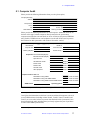
Computer Audit ...................................................................................................
System Installation Checklist
.................................................................
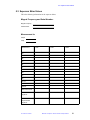
Supercon Shim Values .........................................................................................
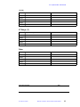
Liquids Probes Test Results ................................................................................
Resolution and Lineshape (50%/0.55%/0.11%, Hz) ..................................
Spinning Sidebands ....................................................................................
90 Pulse Width ( s) ......................................................................................
Sensitivity (S/N) .........................................................................................
γH2 (Hz) ......................................................................................................
VT Range ( C) .............................................................................................
Other ............................................................................................................
5.5 Console and Magnet Test Results .......................................................................
77
79
81
83
84
84
84
84
85
85
85
87
Index................................................................................................................... 89
4
MERCURY Acceptance Test Procedures and Specifications
87-192327-00 E0997
List of Figures
Figure 1. 1H lineshape spinning measurement ..............................................................................
Figure 2. Normal 1H spectrum of 13CH3I .....................................................................................
Figure 3. pwx calibration, coarse (left) and fine (right) ................................................................
Figure 4. HMQC with and without X-nucleus pulses ...................................................................
Figure 5. Normal 1H spectrum of 13CH3I .....................................................................................
Figure 6. pwx calibration, coarse (left) and fine (right) ................................................................
Figure 7. pwx calibration, coarse (left) and fine (right) .................................................................
Figure 8. 1H sensitivity measurement ............................................................................................
Figure 9. 13C Sensitivity ................................................................................................................
87-192327-00 E0997
MERCURY Acceptance Test Procedures and Specifications
22
33
34
35
37
38
40
44
48
5
List of Tables
Table 1. Test order for each probe that observes 1H, 13C, 19F, or 31P ...........................................
Table 2. Test order for probes that observe 29Si, 15N, or indirect detection ..................................
Table 3. Samples for 1H resolution, lineshape, and spinning sidebands tests ...............................
Table 4. Samples for 13C resolution, lineshape, and spinning sidebands tests ..............................
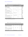
Table 5. Resolution and lineshape specifications for broadband systems ....................................
Table 6. Resolution and lineshape specifications for 4-nucleus systems ......................................
Table 7. Spinning sidebands specifications for broadband systems .............................................
Table 8. Spinning sidebands specifications for 4-nucleus systems ...............................................
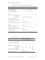
Table 9. Samples for 90 pulse width andγH2 tests ........................................................................
Table 10. 90° pulse width and γH2 specifications for broadband systems ...................................
Table 11. 90° pulse width and γH2 specifications for 4-nucleus systems .....................................
Table 12. Samples for sensitivity tests ...........................................................................................
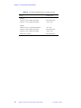
Table 13. Sensitivity (S/N) specifications for broadband systems ................................................
Table 14. Sensitivity (S/N) specifications for 4-nucleus systems .................................................
Table 15. VT range specifications for broadband systems ...........................................................
Table 16. VT range specifications for 4-nucleus systems .............................................................
Table 17. Magnet Drift Specifications ...........................................................................................
6
MERCURY Acceptance Test Procedures and Specifications
87-192327-00 E0997
18
18
62
62
63
63
64
64
65
66
66
67
68
68
69
70
71
SAFETY PRECAUTIONS
Observe the following safety precautions during installation, operation,
maintenance, and repair of this instrument. Failure to comply with these
precautions, or with specific warnings and cautions elsewhere, violates
safety standards of design, manufacture, and intended use of the
instrument. Varian assumes no liability for customer failure to comply with
these precautions.
The following warning and caution illustrate the style used in Varian manuals for safety
precaution notices and explain when each type is used:
WARNING: Warnings are used when failure to observe instructions or precautions
could result in injury or death to humans or animals, or significant
property damage.
CAUTION:
Cautions are used when failure to observe instructions could result in
permanent damage to equipment or data.
WARNINGS
Cardiac pacemaker and metal prosthetics wearers must remain more than
2.8 meters (9 feet) from the magnet system until safety is clearly established.
The MERCURY magnet system generates strong magnetic and electromagnetic fields
that can affect operation of some cardiac pacemakers or harm a metal prosthesis.
Pacemaker wearers should consult the user manual provided by the pacemaker
manufacturer or contact the pacemaker manufacturer to determine the effect on a
specific pacemaker. Pacemaker wearers should always notify their physician and
discuss the health risks of being in proximity to magnetic fields. Wearers of metal
prosthetics should contact their physician to determine if a danger exists. The following
table may help determine the effect of a system on pacemakers or a metal prosthesis.
The table shows the radial (i.e., horizontal) and axial (vertical) extent of the 5-gausslevel stray magnetic field as measured from the magnet center:
Proton Frequency
(MHz)
Bore
(mm)
Radial Extent
(m)
Axial Extent
(m)
200
54
1.50
1.50
200 long-hold
54
2.20
2.80
300
54
1.64
2.05
300 long-hold
54
2.20
2.80
400
54
2.20
2.80
400 long-hold
54
2.20
2.80
Refer to the MERCURY Installation Planning Guide for additional stray magnetic field
plots and the effect of the stray field on electronic equipment. Varian provides signs
containing this warning with each system. Post the signs according to the directions on
the sign. Additional signs are available by request.
87-192327-00 E0997
MERCURY Acceptance Test Procedures and Specifications
7
WARNINGS (continued)
Keep metal objects at least 2.8 meters (9 feet) away from the magnet.
The strong magnetic field of the dewar attracts objects containing steel, iron, or other
“magnetic” materials, such as tools, electronic equipment, compressed gas cylinders,
steel chairs, and steel carts. Unless restrained, such objects can suddenly fly towards
the magnet, causing personal injury and extensive damage to the probe, the dewar, and
the superconducting solenoid. Only nonferromagnetic materials (such as plastics,
aluminum, wood, and stainless steel) should be used in the area around the magnet
dewar.
Only qualified maintenance personnel shall remove equipment covers or
make internal adjustments.
Dangerous high voltages exist inside the equipment that can kill or injure.
Do not substitute parts or modify the instrument.
Any unauthorized modification could injure personnel or damage equipment and
potentially terminate the warrantee agreements and/or service contract. Written
authorization approved by the MERCURY product manger of Varian, Inc. is required to
implement any changes to the hardware of the spectrometer. Maintain safety features
by referring service to a Varian service office.
Do not operate in the presence of flammable gases or fumes.
Operation with flammable gases or fumes present creates the risk of injury or death
from toxic fumes, explosion, or fire.
Leave area immediately in the event of a magnet quench.
If the magnet dewar should quench (sudden appearance of gasses from the top of the
dewar), leave the area immediately. Sudden release of helium or nitrogen gases can
rapidly displace oxygen in an enclosed space creating a possibility of asphyxiation. Do
not return until the oxygen level returns to normal.
Avoid helium or nitrogen contact with any part of the body.
In contact with the body, helium and nitrogen can cause an injury similar to a burn.
Never place your head over the helium and nitrogen exit tubes on top of the magnet. If
helium or nitrogen contacts the body, seek immediate medical attention, especially if
the skin is blistered or the eyes are affected.
8
MERCURY Acceptance Test Procedures and Specifications
87-192327-00 E0997
WARNINGS (continued)
On magnets with removable quench tubes, keep the tubes in place except
during helium servicing.
Oxford 80-day hold 200/54 and 300/54 superconducting magnets (ALOX) include
removable helium vent tubes. If the magnet dewar should quench (sudden appearance
of gasses from the top of the dewar) and the vent tubes are not in place, the helium gas
would be partially vented sideways, possibly injuring the skin and eyes of personnel
beside the magnet. During helium servicing, when the tubes must be removed, follow
carefully the instructions and safety precautions given in the Oxford documentation.
Do not look down the upper barrel.
Unless the probe is removed from the magnet, never look down the upper barrel. You
could be injured by the sample tube as it ejects pneumatically from the probe.
Do not exceed the boiling or freezing point of a sample during variable
temperature experiments.
A sample tube subjected to a change in temperature can build up excessive pressure,
which can break the sample tube glass and cause injury by flying glass and toxic
materials. To avoid this hazard, establish the freezing and boiling point of a sample
before doing a variable temperature experiment.
Support the magnet and prevent it from tipping over.
The magnet dewar has a high center of gravity and could tip over in an earthquake or
after being struck by a large object, injuring personnel and causing sudden, dangerous
release of nitrogen and helium gases from the dewar. To prevent tip-over, at least two
ropes (each rated at least twice the weight of a full magnet) should be suspended from
the ceiling on either side of the magnet and firmly attached to the upper part of the
magnet. The ropes must not be under tension, since this could transfer building
vibrations to the magnet and affect NMR spectra. To calculate rope size and ceiling
attachment points, refer to the site installation plan for the weight and height of the
magnet. On 80-day hold 200/54 and 300/54 magnets (ALOX) only, an alternative is to
bolt the magnet to the floor; however, floor mounting can be used only if it is first
confirmed that floor vibration will not interfere with the operation of the spectrometer.
87-192327-00 E0997
MERCURY Acceptance Test Procedures and Specifications
9
CAUTIONS
Keep magnetic tapes, credit cards, and watches away from the magnet
dewar.
Most personal plastic cards, such as automated teller (ATM) and credit cards, contain
a strip of magnetic media that can damaged by a strong magnetic field. Many wrist and
pocket watches are also susceptible to damage from intense magnetism.
Check helium and nitrogen gas flowmeters daily.
Record the readings to establish the operating level. The readings will vary somewhat
because of changes in barometric pressure from weather fronts. If the readings for
either gas should change abruptly, contact qualified maintenance personnel. Failure to
correct the cause of abnormal readings could result in extensive equipment damage.
Do not remove the relief valves on the vent tubes.
The relief valves prevent air from entering the nitrogen and helium vent tubes. Air that
enters the magnet will contain moisture that can freeze, causing blockage of the vent
tubes and possibly extensive damage to the magnet. Except when transferring nitrogen
or helium, be certain that the relief valves are secured on the vent tubes.
Radio-Frequency Emission Regulations
The covers on the instrument form a barrier to radio-frequency (rf) energy. Removing
any of the covers or modifying the instrument may lead to increased susceptibility to
rf interference within the instrument and may increase the rf energy transmitted by the
instrument in violation of regulations covering rf emissions. It is the operator’s
responsibility to maintain the instrument in a condition that does not violate rf emission
requirements.
10
MERCURY Acceptance Test Procedures and Specifications
87-192327-00 E0997
Chapter 1.
Introduction
Following each installation of a Varian MERCURY NMR spectrometer system, an
installation engineer tests and demonstrates the instrument’s operation.
1.1 Overview
The procedures for the acceptance tests, as well as specifications, are provided in this
manual. The forms for entering the test results are provided in Chapter 5, “Acceptance
Test Results,” beginning on page 75. The forms follow the same sequence as the tests.
Acceptance Tests
The objectives of the acceptance tests procedures are threefold:
• To identify the tests to be performed during system installation.
• To identify the precise methods by which these tests are performed.
• To leave the instrument in a calibrated, ready to use, state.
The procedures are arranged by the type of specification. The arrangement of the
procedures does not matter (although some procedures use results from other
procedures) and is determined by the installation engineer. These procedures cover the
basic specifications of the instrument—signal-to-noise (S/N), resolution, and
lineshape—and are not intended to reflect the full range of operating capabilities or
features of a MERCURY NMR spectrometer. Performance of any additional tests
beyond those described in this manual must be agreed upon in writing as part of the
customer contract.
Acceptance Specifications
All specifications are subject to change without notice. The specifications published in
this manual shall prevail unless negotiation or customer contract determines otherwise.
Refer to the text in each chapter for other conditions. Request of any additional
specifications beyond those listed in this manual must be agreed upon in writing as part
of the customer contract.
The following policies are in effect at installation:
• Specifications Policy for Probes Used in Systems other than MERCURY—No
guarantee is given that probes purchased for use in systems other than MERCURY
will meet current specifications.
• Testing Policy for Indirect Detection Probes used for Direct Observe Broadband
Performance—Probes designed for indirect detection applications are tested for
87-192327-00 E0997
MERCURY Acceptance Test Procedures and Specifications
11
Chapter 1. Introduction
indirect detection performance only. Indirect detection acceptance tests are
performed only if an indirect detection probe was purchased for use with the
MERCURY.
• Sample Tubes Policy—Tests are performed in 5-mm sample tubes with 0.38 mm
wall thickness (Wilmad 528-PP, or equivalent) and 10-mm sample tubes with 0.46
mm wall thickness (Wilmad 513-7PP, or equivalent). Using sample tubes with
thinner walls (Wilmad 5-mm 545-PPT, or equivalent; Wilmad 10-mm 513-7PPT,
or equivalent) increases signal-to-noise.
Computer Audit
A computer audit form is included in “Computer Audit” on page 77. The information
from this form will help Varian assist you better in distributing future software
upgrades and avoiding hardware compatibility problems. You are asked for
information about all computers directly connected to the spectrometer or else used to
process NMR data.
Installation Checklist
An installation checklist form is given in “System Installation Checklist” on page 79.
System Documentation Review
Following the completion of the acceptance tests and computer audit, the installation
engineer will review the following system documentation with the customer:
• Software Object Code License Agreement.
• Varian and OEM manuals.
• Warranty coverage and where to telephone for information.
Basic System Demonstration
The installation engineer will also demonstrate the basic operation of the system to the
laboratory staff. The objective of the demonstration is to familiarize the customer with
system features and safety requirements, as well as to assure that all mechanical and
electrical functions are operating properly.
The system demonstration includes the following items:
Magnet Demonstration
• Posting requirements for magnetic field warning signs
• Cryogenics handling procedures and safety precautions
• Magnet refilling
• Flowmeters
• Homogeneity disturbances
Console and Probe Demonstration
• Loading programs.
12
MERCURY Acceptance Test Procedures and Specifications
87-192327-00 E0997
1.2 General Acceptance Testing Requirements
• Experiment setup, including installing the probe in the magnet.
• Basic instrument operation to obtain typical spectra, including probe tuning,
magnet homogeneity shimming, and printer/plotter operation. (Note that Varian
installation engineers are neither responsible for nor trained to run any spectra
not described in the Acceptance Tests Procedures.)
• Demonstration of GLIDE 1H and 13C operation.
• Demonstration of GLIDE APT and DEPT experiments.
• Demonstration of (optional) homonuclear decoupling.
Detailed specifications and circuit descriptions are not covered.
Formal training in the operation and maintenance of the spectrometer is conducted by
Varian at periodically scheduled training seminars held in most Varian Application
Laboratories. On-site training is available in some geographic locations. Contact your
sales representative for further information on availability and pricing for these
courses.
To make the system demonstration most beneficial, the customer should review Varian
and OEM operation and reference manuals before viewing the demonstration.
1.2 General Acceptance Testing Requirements
Each Varian MERCURY spectrometer is designed to provide high-resolution
performance when operated in an environment as specified in the MERCURY
Installation Planning Guide. Unless both the specific requirements of this Acceptance
Test Procedures manual and the general requirements specified in the MERCURY
Installation Planning Guide are met, Varian cannot warrant that the NMR spectrometer
system will meet the published specifications.
General Requirements
• The MERCURY performance specifications in effect at the time of your order are
used to evaluate the system.
• The appropriate quarter-wavelength cable must be used for each nucleus.
• Homogeneity settings must be optimized for each sample (manual shimming may
be required in any or all cases). The shim parameters for resolution tests on each
probe should be recorded in a log book and in a separate file name (in the directory
/vnmr/shims) for each probe. For example, for a 5-mm switchable probe, the
shim parameters can be saved with the command svs('sw5res'). These values
can then be used as a starting point when adjusting the homogeneity on unknown
samples, by the command rts('sw5res').
• The probe must be tuned to the appropriate frequency.
• The spinning speed must be set to the following:
Sample (mm)
Nuclei
Speed (Hz)
5
all
20–26
10
all
15
Spinning 10-mm tubes faster than 15 Hz may cause vortexing in samples, severely
degrading the resolution.
87-192327-00 E0997
MERCURY Acceptance Test Procedures and Specifications
13
Chapter 1. Introduction
• Some test parameters are stored in the disk library /vnmr/tests and can be
recalled by entering rtp('/vnmr/tests/xxx'), where xxx is the name of the
file that contains the parameters to be retrieved—for example, rtp('/vnmr/
tests/H1sn'). To see the parameter sets available for the standard tests, enter
ls('/vnmr/tests'). Other sets come from /vnmr/stdpar.
• For all sensitivity tests, the value of pw must be changed to the value of the 90°
pulse found in the pulse width test on the same probe.
• During calibration, GLIDE creates an appropriate pw array to determine the 90°
pulse width. For manually run observe pulse width tests, an appropriate array of
pw values must be entered to determine the 180° pulse. The 180° pulse is the first
non-zero pulse that gives minimum intensity of the spectrum. The 180° pulse is
usually determined by interpolation between a value that gives a positive signal,
and a value that gives a negative signal. The 90° pulse width is one half the 180°
pulse.
• Signal-to-noise (S/N) is measured by the computer as follows:
S/N =
maximum amplitude of peak
2 x root mean square of noise region
• Lineshape should be measured digitally with the aid of the system software. The
properly scaled spectra should also be plotted and the plot retained.
• Digital determination of lineshape:
1. Display and expand the desired peak.
2. Enter nm, then dc for drift correction to ensure a flat baseline. Set
vs=10000. Click the menu button labeled Th to display the horizontal
threshold cursor. Set th=55 (the 0.55% level).
3. Click the menu button labeled Cursor or Box until two vertical cursors are
displayed, and align them on the intersections of the horizontal cursor and
the peak. Type delta? to see the difference in Hz between the cursors.
4. Set th=11 (the 0.11% level) and repeat.
• Determination of lineshape from a plot:
1. Use a large enough plot width to allow accurate determination of the
baseline. The baseline should be drawn through the center of the noise, in
a region of the spectrum with no peaks.
2. The 0.55% and 0.11% levels are then measured from the baseline and
calculated from the height of the peak and the value of vs. For example,
if a peak is 9.0 cm high with vs=200, then the 0.55% level on a 100-fold
vertical expansion (vs=20000) is 9.0 × 0.55, or 4.95 cm from the
baseline.
If the noise is significant at the 0.55% and 0.11% levels, the linewidth should be
measured horizontally to the center of the noise.
• For all sensitivity tests, a noise region free of any anomalous features should be
chosen with the cursors. Neither cursor should be placed any closer to an edge of
the spectrum than 10 percent of the value of sw. This should produce the best
possible signal-to-noise that is representative of the spectrum.
• The results of all tests should be plotted to create a permanent record. Include a
descriptive label and a list of parameters. These plots can then be saved as part of
the acceptance tests documentation.
14
MERCURY Acceptance Test Procedures and Specifications
87-192327-00 E0997
Part 1:
Acceptance Test
Procedures
Chapter 2 Liquids Probes Test Procedures
Chapter 3 Console and Magnet Test Procedures
Chapter 2.
Liquids Probes Test Procedures
This chapter contains procedures for both required and optional liquids probes tests.
Specifications to be demonstrated are contained in Part 2 of this manual.
Write the results of each probe test on the forms provided in “Liquids Probes Test
Results” on page 83.
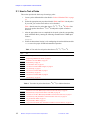
The following is a list of the sections in this chapter:
• 2.1 “How to Test a Probe,” page 18
• 2.2 “Probe Calibration Files,” page 19
• 2.3 “Resolution, Lineshape, and Spinning Sidebands Procedures,” page 20
• 2.4 “90 Pulse Width Procedures,” page 25
• 2.5 “Sensitivity Procedures,” page 42
• 2.6 “Configuring Solvent-Based Shims and setlk for GLIDE,” page 51
87-192327-00 E0997
MERCURY Acceptance Test Procedures and Specifications
17
Chapter 2. Liquids Probes Test Procedures
2.1 How to Test a Probe
This section provides the basic steps for testing a probe.
1. Create a probe calibration file as described in “Probe Calibration Files” on page
19.
2. Follow the appropriate test procedures listed in Table 1 and Table 2 for the probe.
If you wish, you can check off each test as it is finished.
Table 1 lists the tests for probes that observe 1H, 13C, 19F, or 13P. Table 2 lists
the test for probes that observe 15N or 29Si and probes capable of indirect
detection.
3. After the appropriate tests are completed for the probe, print the corresponding
probe calibration file by entering the following command in the VNMR input
window:
ACreport
4. Follow the instructions Section 2.6 for configuring solvent-based shims and the
setlk macro for proper GLIDE and automation operation.
Table 1. Test order for each probe that observes 1H, 13C, 19F, or 31P
Done
Test
1H Spinning Resolution and Lineshape (50%, 0.55%, 0.11%) of CHCl3, on page 21
1H Spinning Sidebands of CHCl3, on page 23
1H Observe 90 Pulse Width, on page 26
1H Sensitivity, on page 43
13C Resolution Test, on page 24
13C Observe 90 Pulse Width and gH2, on page 29
13C Sensitivity, on page 47
19F Observe 90 Pulse Width, on page 27
19F Sensitivity, on page 45
31P Observe 90 Pulse Width, on page 28
31P Sensitivity, on page 46
Table 2. Test order for probes that observe 29Si, 15N, or indirect detection
Done
Test
29Si Observe 90 Pulse Width (Only 4-Nucleus Probes with 29Si), on page 30
29Si Sensitivity (Only 4-Nucleus Probes with 29Si), on page 49
15N Observe 90 Pulse Width (Only 400-MHz or 4-Nuc Probes with 15N), on page 31
15N Sensitivity (Only 400-MHz or 4-Nucleus Probes with 15N), on page 50
13C pwx90 Pulse Width, on page 32
31P pwx90 Pulse Width, on page 36
15N pwx90 Pulse Width (Only 400-MHz with Indirect Detection Probes), on page 39
18
MERCURY Acceptance Test Procedures and Specifications
87-192327-00 E0997
2.2 Probe Calibration Files
2.2 Probe Calibration Files
VNMR 5.3 software includes probe calibration files in the directory /vnmr/probes.
Probe calibration files contain pw90, tpwr, dmf, dpwr, and pwx settings for each
probe used with the system. GLIDE, automation, and manual operation using
macros—including h1, hcosy, and dept—retrieve appropriate power levels, the
pw90 value, and the dmf value from the probe calibration file, instead of using preset
values in the parameters files. Successful operation depends on the existence of a
probe calibration file for each probe that is used with the system.
When the MERCURY NMR spectrometer is installed, the proper probe calibration files
are set up, so that the system is ready to use when the installer leaves the site.
The probe calibration files must be created when the system is installed or the first time
a probe is used. Create or change the probe calibration file as follows:
To Create a Probe Calibration File
Do these steps for each probe that is tested.
1. Log in as vnmr1.
2. Enter the following command in the VNMR input window:
addprobe('probe_name','system')
Where probe_name is a descriptive name for the probe. For example, sw5mm
for a 5-mm switchable probe, or 4nucPFG for a 4-nucleus PFG probe. The
'system' argument makes the probe calibration files for this probe avaible to
all users by placing the files in /vnmr/probes. Without the argument, the files
are placed in the vnmrsys directory of the user who entered the command (e.g.,
~vnmr1/vnmrsys/probes) and are only available to that user..
The values for power, pw90, dmf, and pp are initially set to 0 and filled in later
by running the calibration procedures for 1H, 19F, 31P, and 13C using GLIDE.
To Change to a Different Probe Calibration File
After the probes are tested and calibrated, use this procedure to switch to the
appropriate calibration file when a different probe is installed.
1. Log in as vnmr1.
2. Enter the following command in the VNMR input window;
probe='probe_name'
Where probe_name is the name of the directory in /vnmr/probes named for
the new probe (e.g., sw5mm).
87-192327-00 E0997
MERCURY Acceptance Test Procedures and Specifications
19
Chapter 2. Liquids Probes Test Procedures
2.3 Resolution, Lineshape, and Spinning Sidebands
Procedures
The procedures in this section demonstrate the resolution, lineshape, and spinning
sidebands (SSB) specifications listed in “Resolution, Lineshape, Spinning Sidebands
Specifications” on page 62.
•
•
•
20
1H Spinning Resolution and Lineshape (50%, 0.55%, 0.11%) of CHCl3
1H Spinning Sidebands of CHCl3
13C Resolution Test
MERCURY Acceptance Test Procedures and Specifications
87-192327-00 E0997
2.3 Resolution, Lineshape, and Spinning Sidebands Procedures
1H
Spinning Resolution and Lineshape (50%, 0.55%, 0.11%) of
CHCl3
Samples
Amplitude Level
Sample
Tube (mm)
Test Sample
Part No.
50.0%, 0.55%, 0.11%
5
20% chloroform in acetone–d6
00-968120-76
50.0%, 0.55%, 0.11%
5
5% chloroform in acetone–d6
00-968120-99
50.0%, 0.55%, 0.11%
4
5% chloroform in acetone–d6
00-993143-99
50.0%, 0.55%, 0.11%
5
1% chloroform in acetone–d6
00-968120-89
50.0%, 0.55%, 0.11%
10
1% chloroform in acetone–d6
00-968123-89
Procedure
The 1H lineshape test (this test) and the 1H spinning sidebands test (the next test) must
be passed simultaneously and both tests plotted together.
1. Insert the appropriate CHCl3 sample in the magnet and spin it.
2. Enter rtp('/vnmr/tests/H1lshp') nm and set nt=1 vs=100. Enter su
to set up the system hardware.
3. Tune the probe.
4. Enter a value for pw appropriate for your sample:
If your sample is:
Then use the value for a:
1% CHCl3, (00-968120-89)
90 pulse
5% CHCl3, (00-968120-99)
30 pulse
20% CHCl3, (00-968120-76)
20 pulse
5. Enter ga to acquire the spectrum. Phase the spectrum, set wp=250, and plot
using pl. Increase vs by a factor of 100 times and plot the expanded spectrum
using pl pscale page.
If floor vibration results in excessive noise around the base of the peak, nt can
be set to a larger value (e.g., nt=4 or nt=16); however, if extreme vibrations
are present, it may be impossible to measure the lineshape accurately.
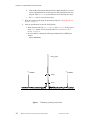
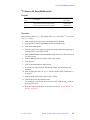
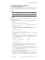
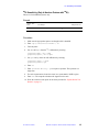
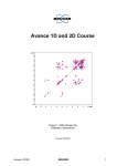
6. Measure lineshape as the linewidth of the CHCl3 peak at 50%, 0.55% and 0.11%
of the main peak amplitude. Refer to Figure 1 and use the substeps below to
determine the lineshape:
a.
Display and expand the desired peak.
b.
Enter nm, then dc for drift correction to ensure a flat baseline. Set
vs=10000. Place a cursor on the chloroform line and enter nl dres (the
50% level).
c.
Enter nm, then dc for drift correction to ensure a flat baseline. Set
vs=10000. Click the VNMR menu button labeled Th to display the
horizontal threshold cursor. Set th=55 (the 0.55% level).
87-192327-00 E0997
MERCURY Acceptance Test Procedures and Specifications
21
Chapter 2. Liquids Probes Test Procedures
d. Click the first menu button labeled Cursor or Box to display two vertical
cursors, and align them on the intersections of the horizontal cursor and
the peak. Enter delta? to see the difference in Hz between the cursors.
e.
Set th=11 (the 0.11% level) and repeat.
7. Write the results for each probe in the forms provided in “Liquids Probes Test
Results” on page 83.
8. After the specifications are met, do the following:
• Write down the values for z0, lockpower, and lockgain as they appear
in the Acqi window. Use the forms provided in “Liquids Probes Test
Results” on page 83.
• Save the shims by entering the following command in the VNMR input
window:
svs('acetone')
CHCl3 peak
13C
13C
satellite
satellite
0.55%
0.11%
140
120
100
80
60
40
20
0
-20
-40
-60
-80
-100 -120
Figure 1. 1H lineshape spinning measurement
22
MERCURY Acceptance Test Procedures and Specifications
87-192327-00 E0997
Hz
2.3 Resolution, Lineshape, and Spinning Sidebands Procedures
1H
Spinning Sidebands of CHCl3
Samples
Amplitude Level
Sample
Tube (mm)
Test Sample
Part No.
50.0%, 0.55%, 0.11%
5
20% chloroform in acetone–d6
00-968120-76
50.0%, 0.55%, 0.11%
5
5% chloroform in acetone–d6
00-968120-99
50.0%, 0.55%, 0.11%
4
5% chloroform in acetone–d6
00-993143-99
50.0%, 0.55%, 0.11%
5
1% chloroform in acetone–d6
00-968120-89
50.0%, 0.55%, 0.11%
10
1% chloroform in acetone–d6
00-968123-89
Procedure
The 1H spinning sidebands test (this test) and the 1H lineshape test (the previous test)
must be passed simultaneously and both tests plotted together.
1. Using the appropriate CHCl3 sample, measure the 1H spinning sidebands on the
same spectrum as the 1H lineshape test.
2. Use the spectra and parameter set from the lineshape test. Plot the spectrum
again using a large enough value of wp to show all the spinning sidebands.
3. Measure spinning sideband amplitudes as a percentage of the main peak.
Spinning sidebands occur at frequency intervals on either side of the central peak
equal to the spinning rate. The sidebands might not be split.
4. The standard test requires nt=4. If the sidebands meet specifications at nt=4,
repeating the test at nt=16 is not necessary.
5. Write the results for each probe in the forms provided in “Liquids Probes Test
Results” on page 83.
87-192327-00 E0997
MERCURY Acceptance Test Procedures and Specifications
23
Chapter 2. Liquids Probes Test Procedures
13C
Resolution Test
Samples
Amplitude Level
Sample
Tube (mm)
50.0%, 0.55%, 0.11%
50.0%, 0.55%, 0.11%
Test Sample
Part No.
5
40% p-dioxane in benzene–d6
(ASTM)
00-968120-69
10
40% p-dioxane in benzene–d6
(ASTM)
00-968123-69
Procedure
1. Enter rtp('/vnmr/tests/C13res') su.
2. Tune the probe.
3. Set nt=4 and lb='n'. Set the decoupler modulation to dmm='c' and d1=60.
4. Set the sample spinning rate at 20 ± 5 Hz.
5. Enter ga to acquire the spectrum. Plot the spectrum using wp=50, and use dres
to determine the linewidth at 50% of the decoupled peak.
6. If decoupling is not complete, run a proton spectrum and set the cursor at the
center of the single peak. Enter movetof, then enter tof? to display the new
values of tof. Record the value.
7. Enter jexpn, where n is the experiment number of the carbon experiment (e.g.,
jexp2 to join experiment 2), and set dof to the value of tof obtained in the
proton spectrum.
8. Repeat step 5.
9. Write the results for each probe in the forms provided in “Liquids Probes Test
Results” on page 83.
24
MERCURY Acceptance Test Procedures and Specifications
87-192327-00 E0997
2.4 90 Pulse Width Procedures
2.4 90 Pulse Width Procedures
This section contains the procedures required to demonstrate the specifications listed
in “90 Pulse Width and gH2 Specifications” on page 65.
•
•
•
•
•
•
•
•
•
1H Observe 90 Pulse Width
19F Observe 90 Pulse Width
31P Observe 90 Pulse Width
13C Observe 90 Pulse Width and gH2
29Si Observe 90 Pulse Width (Only 4-Nucleus Probes with 29Si)
15N Observe 90 Pulse Width (Only 400-MHz or 4-Nuc Probes with 15N)
13C pwx90 Pulse Width
31P pwx90 Pulse Width
15N pwx90 Pulse Width (Only 400-MHz with Indirect Detection Probes)
Refer to other Varian manuals for further information on pulse width determination.
87-192327-00 E0997
MERCURY Acceptance Test Procedures and Specifications
25
Chapter 2. Liquids Probes Test Procedures
1H
Observe 90 Pulse Width
Samples
Sample Tube
(mm)
Sample
Part Number
Test Sample
5
0.1% ethylbenzene, 0.01% TMS
99.89% deuterochloroform (CDCl3)
00-968120-70
10
0.1% ethylbenzene, 0.01% TMS
99.89% deuterochloroform (CDCl3)
00-968123-70
4
0.1% ethylbenzene, 0.01% TMS
99.89% deuterochloroform (CDCl3)
00-993143-99
Procedure
This procedure calibrates tpwr and the 90 pulse width for1H.
1. Open GLIDE by clicking the GLIDE button in the VNMR menu.
2. Click on the Setup icon.
3. Insert the sample in the magnet using either the manual button on the magnet leg
or the Insert button in the Setup window.
4. Select Calibrate Proton from the Experiment drop-down menu. You do not need
to select a solvent.
5. Click the Setup button at the bottom of the Setup window.
6. Tune the probe.
7. Click on the Acquire button under Custom.
8. If you have already locked and shimmed the sample, turn off autolock and
autoshim.
9. Enter an appropriate value for pwmax, which is listed in Table 10 and Table 11
on page 66.
10. Click on Close at the bottom of the Acquire window.
11. Click the Go icon in the GLIDE window.
You should get a plot of arrayed spectra.
12. Write the results for each probe in the forms provided in “Liquids Probes Test
Results” on page 83.
26
MERCURY Acceptance Test Procedures and Specifications
87-192327-00 E0997
2.4 90 Pulse Width Procedures
19F
Observe 90 Pulse Width
Sample
Sample Tube
(mm)
Test Sample
Sample
Part Number
5
0.05% trifluorotoluene in benzene–d6
00-968120-82
Procedure
This procedure calibrates tpwr and the 90 pulse width for19F.
1. Open GLIDE by clicking the GLIDE button in the VNMR menu.
2. Click on the Setup icon.
3. Insert the sample in the magnet using either the manual button on the magnet leg
or the Insert button in the Setup window.
4. Select Calibrate Florine from the Experiment drop-down menu. You do not need
to select a solvent.
5. Click the Setup button at the bottom of the Setup window.
6. Tune the probe.
7. Click on the Acquire button under Custom.
8. If you have already locked and shimmed the sample, turn off autolock and
autoshim.
9. Enter an appropriate value for pwmax, which is listed in Table 10 and Table 11
on page 66.
10. Click on Close at the bottom of the Acquire window.
11. Click the Go icon in the GLIDE window.
You should get a plot of arrayed spectra.
12. Write the results for each probe in the forms provided in “Liquids Probes Test
Results” on page 83.
87-192327-00 E0997
MERCURY Acceptance Test Procedures and Specifications
27
Chapter 2. Liquids Probes Test Procedures
31P
Observe 90 Pulse Width
Samples
Sample Tube
(mm)
Test Sample
Sample
Part Number
5
0.0485 M triphenylphosphate in CDCl3
00-968120-87
10
0.0485 M triphenylphosphate in CDCl3
00-968123-87
Procedure
This procedure calibrates tpwr and the 90 pulse width for31P.
1. Make sure the appropriate quarter-wavelength cable is installed.
2. Open GLIDE by clicking the GLIDE button in the VNMR menu.
3. Click on the Setup icon.
4. Insert the sample in the magnet using either the manual button on the magnet leg
or the Insert button in the Setup window.
5. Select Calibrate Phosphorus from the Experiment drop-down menu. You do not
need to select a solvent.
6. Click the Setup button at the bottom of the Setup window.
7. Tune the probe.
8. Click on the Acquire button under Custom.
9. If you have already locked and shimmed the sample, turn off autolock and
autoshim.
10. Enter an appropriate value for pwmax, which is listed in Table 10 and Table 11
on page 66.
11. Click on Close at the bottom of the Acquire window.
12. Click the Go icon in the GLIDE window.
You should get a plot of arrayed spectra.
13. Write the results for each probe in the forms provided in “Liquids Probes Test
Results” on page 83.
28
MERCURY Acceptance Test Procedures and Specifications
87-192327-00 E0997
2.4 90 Pulse Width Procedures
13C
Observe 90 Pulse Width andγH2
Samples
Sample Tube
(mm)
Test Sample
Sample
Part Number
5
40% p-dioxane in benzene–d6 (ASTM)
00-968120-69
10
40% p-dioxane in benzene–d6 (ASTM)
00-968123-69
Procedure
This procedure calibrates tpwr, the 90 pulse width, dpwr, and γH2 for 13C, as well set
dmf, pplvl, and pp.
1. Make sure the appropriate quarter-wavelength cable is installed.
2. Open GLIDE by clicking the GLIDE button in the VNMR menu.
3. Click on the Setup button.
4. Insert the sample in the magnet using either the manual button the magnet leg or
the Insert button in the Setup window.
5. Select Calibrate Carbon from the Experiment drop-down menu. You do not need
to select a solvent.
6. Click the Setup button at the bottom of the Setup window.
7. Tune the probe.
8. Click on the Acquire button under Custom.
9. If you have already locked and shimmed the sample, turn off autolock and
autoshim.
10. Enter an appropriate value for pwmax, which is listed in Table 10 and Table 11
on page 66.
11. Click on Close at the bottom of the Acquire window.
12. Click the Go icon in the GLIDE window.
You should get a plot of arrayed spectra for 90 pulse width andγH2, as well as
arrayed spectra for pp.
13. Write the results for each probe in the forms provided in “Liquids Probes Test
Results” on page 83.
87-192327-00 E0997
MERCURY Acceptance Test Procedures and Specifications
29
Chapter 2. Liquids Probes Test Procedures
29Si
Observe 90 Pulse Width (Only 4-Nucleus Probes with 29Si)
This test is only for 4-nucleus probes with 29Si.
Sample
Sample Tube
(mm)
Test Sample
Sample
Part Number
5
25% hexamethyldisiloxane in benzene–d6
00-968120-98
Procedure
1. Make sure the appropriate quarter-wavelength cable is installed.
2. Insert the sample into the magnet.
3. Enter rtp('/vnmr/tests/Si29sn') su.
4. Tune the probe observe channel without using the filter.
5. Enter addnucleus('Si29') to add an entry for 29Si to the probe calibration
file.
6. Set d1=200 at=6 fn=8k sw=2k dm='y' dmm='w'
7. If you already calibrated 13C, you can retrieve dpwr and dmf with the following
commands:
getparam('dpwr','H1'):dpwr
getparam('dmf','H1'):dmf
8. Enter ga.
9. Enter ds. Set vs=50 and adjust vs so that the peak occupies about half the
screen.
10. Set a cursor on the peak. Enter movetof pw=10,20,30,40,50,60,70,80
ga.
11. When the last spectrum is obtained, enter dssh.
The first null spectra is the 180 pulse; therefore, the 90 pulse width is one half
the 180 pulse.
12. Store the tpwr used and the 90 pulse width found by entering the following
commands in the VNMR input window:
setparams('tpwr','58')
setparams('pw90','12.5')
The values are treated as strings; therefore, they are enclosed in single quotes.
13. Write the results for each probe in the forms provided in “Liquids Probes Test
Results” on page 83.
30
MERCURY Acceptance Test Procedures and Specifications
87-192327-00 E0997
2.4 90 Pulse Width Procedures
15N
Observe 90 Pulse Width (Only 400-MHz or 4-Nuc Probes
with 15N)
This test is performed at installation on only 400-MHz systems and broadband systems
with 5-mm 1H/19F/13C/15N 4-nucleus probes, unless explicitly agreed upon in writing
as part of the customer contract.
Samples
Sample Tube
(mm)
Test Sample
Sample
Part Number
5
90% formamide in DMSO–d6
00-968120-83
10
90% formamide in DMSO–d6
00-968123-83
Procedure
1. Make sure the appropriate quarter-wavelength cable and probe tuning rod are
installed.
2. Insert the sample into the magnet.
3. Enter rtp('/vnmr/tests/N15sn') su.
4. Tune the probe observe channel.
5. Set d1=200 at=6 fn=8k sw=2k dm='y' dmm='w'
6. If you already calibrated 13C, you can retrieve dpwr and dmf with the following
commands:
getparam('dpwr','H1'):dpwr
getparam('dmf','H1'):dmf
7. Enter ga.
8. Enter ds. Set vs=50 and adjust vs so that the peak occupies about half the
screen.
9. Set a cursor on the peak. Enter movetof pw=10,20,30,40,50,60,70,80
ga.
10. When the last spectrum is obtained, enter dssh.
The first null spectra is the 180 pulse; therefore, the 90 pulse width is one half
the 180 pulse.
11. Store the tpwr used and the 90 pulse width found by entering the following
commands in the VNMR input window:
setparams('tpwr','58')
setparams('pw90','12.5')
The values are treated as strings; therefore, they are enclosed in single quotes.
12. Write the results for each probe in the forms provided in “Liquids Probes Test
Results” on page 83.
87-192327-00 E0997
MERCURY Acceptance Test Procedures and Specifications
31
Chapter 2. Liquids Probes Test Procedures
13C
pwx90 Pulse Width
This test is only for systems with indirect detection probes.
Sample
Sample Tube
(mm)
Sample
Part Number
Test Sample
1% iodomethane–13C, 1% trimethylphosphite, 0.2%
Cr(acac) in CDCl3
5
00-968120-96
Procedure
To perform the 13C or X-nucleus 90 pulse with calibration in the indirect mode, use the
HMQC experiment.
1. Make sure the appropriate quarter-wavelength cable is installed.
2. Insert the 1% iodomethane–13C sample (Part No. 00-968120-96). Tune the
probe on this sample.
3. Enter rtp('/vnmr/tests/H1sn') to retrieve the parameters from the 1H
sensitivity measurement.
4. Set pw and tpwr to the values determined for the 1H sensitivity procedure; you
can get these values from the probe calibration file by entering:
getparam('tpwr'):tpwr
getparam('pw90'):pw
5. Set gain=10 dn='C13' d1=5 and enter ga.
6. Place two cursors around the region with the peaks. Enter movesw to narrow the
spectral width.
7. Determine the 90 pulse width by arrayingpw to ≥360 pulse width. Enter the
macro array to set up the array. As the macro displays the following prompts,
type in the response shown in bold:
parameter to be arrayed:
number of steps in the array:
starting increment:
array increment:
pw
25
2
2
In the above example, the experiment is set up to array the pw parameter from 2
µs to 52 µs, in 2 µs increments. If the 90 pulse width is 10 µs, the 450 pulse width
corresponds to pw=50 µs (5 * pw90).
8. Enter ga to start the acquisition. After the last spectrum is finished, enter ds(5)
vp=50 to display the fifth spectrum. Enter aph to phase the spectrum, then enter
ai dssh to display the arrayed spectra.
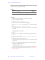
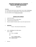
9. Set pw equal to the 90 pulse width you have determined. Ether ga to acquire the
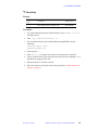
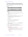
spectrum. Enter f ds to display the spectrum.
The spectrum should appear similar to the example shown in Figure 2. The large,
three-line pattern at about 2.2 ppm is the signal of interest.
32
MERCURY Acceptance Test Procedures and Specifications
87-192327-00 E0997
2.4 90 Pulse Width Procedures
4.0
3.5
3.0
2.5
2.0
1.5
ppm
Figure 2. Normal 1H spectrum of 13CH3I
10. To perform the 13C X-nucleus 90 pulse width calibration in the indirect mode
using HMQC, enter hmqc in the same experiment or move the parameters to a
different experiment by entering mp(x,y), where x is the current experiment
and y is the experiment to which the parameter set is to be moved.
11. Set the following parameters: fn=8192, ni=1, phase=1, nt=1, ss=0,
spin=0 (use acqi to turn the spinner off if the optional spinner hardware is not
installed), d1=5, pw to the 1H 90 pulse width(determined from the previous
steps), tpwr to the tpwr level to give the 1H 90 pulse width (determined from
the previous steps), null=0, j=151, tof to the tof determined from the 1H
spectrum of the 1% iodomethane-13C in step 6 above, dn='C13', dm='nnn',
and dof from the following table:
1H
freq. (MHz)
13C
(Hz)
15N
(Hz)
31P
(Hz)
400
–965
–12000
9000
300
–9000
–9200
7000
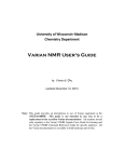
12. To determine the 13C X-nucleus 90 pulse width and rf homogeneity using the
HMQC pulse sequence, pwx is arrayed for a particular pwxlvl. The spectrum
corresponding to the 13C X-nucleus 90 pulse width using the HMQC pulse
sequence is the maximum amplitude spectrum.
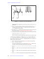
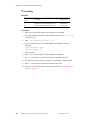
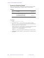
An array of spectra appears as shown in Figure 3. The array shows only the
response of the outer line (at about 2.4 ppm) of the three-line pattern. In HMQC,
null occurs at 45, 135 maximum at 90 and negative at 180 .
Set pwxlvl to the tpwr value for normal 13C observe (to get this value you can
enter getparam('tpwr','C13'):pwxlvl). Enter array to array pwx. As
array displays the following prompts, enter in the responses shown in bold:
parameter to be arrayed:
number of steps in the array:
starting increment:
array increment:
87-192327-00 E0997
pwx
20
2
1
MERCURY Acceptance Test Procedures and Specifications
33
Chapter 2. Liquids Probes Test Procedures
90°
45°
0°
135°
180°
Figure 3. pwx calibration, coarse (left) and fine (right)
In this example, the experiment is set up to array pw from 2 µs to 22 µs, in 1 µs
increments.
13. Enter ga to start the acquisition. After the last spectrum is finished, enter ds(1)
to display the first spectrum. Enter aph to phase the spectrum, then enter ai
dssh to display the arrayed spectra.
14. Determine the pwx90 from the first maximum. Write the results for each probe
in the forms provided in “Liquids Probes Test Results” on page 83.
15. To store the values in the probe calibrations file, enter the following commands:
setparams('pwxlvl','61.0','C13')
setparams('pwx','14.2','C13')
Be sure to enclose the values in single quotes because they are treated as strings.
13C
Decoupling Calibration—Measuring γH2 for Indirect Detection
This procedure describes how to perform 13C decoupling calibration as well as how to
measure γH2 for indirect detection.
1. Set pwx equal to the value determined in step 14 in the previous procedure.
2. Enter ga to acquire a spectrum.
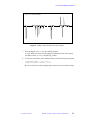
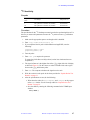
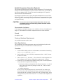
The spectrum should look like the second spectrum in Figure 4, with the outer
two peaks of the three line pattern up and the center peak down.
3. Set dmm='ccc' dm='nny' dpwr=30 dof=dof+2000,dof–2000. Then
enter ga.
4. Enter ds(1), place a cursor on each of the positive peaks, and write down the
delta.
5. Enter ds(2), place a cursor on each of the positive peaks, and write down the
delta.
6. Enter h2cal and enter the delta values for the high field and low field coupling.
34
MERCURY Acceptance Test Procedures and Specifications
87-192327-00 E0997
2.4 90 Pulse Width Procedures
HMQC NT=1 PWX=0,90 DEGREES
Figure 4. HMQC with and without X-nucleus pulses
7. When prompted, enter 151 for the coupling constant.
A γH2 of 5000 is necessary for decoupling in indirect detection. If the value is
not 5000, increase dpwr by 3 dB until γH2 is 5000.
8. To store the values in the probe calibrations file, enter the following commands:
setparams('dpwr','43','C13')
setparams('dmf','20000','C13')
Be sure to enclose the values in single quotes because they are treated as strings.
87-192327-00 E0997
MERCURY Acceptance Test Procedures and Specifications
35
Chapter 2. Liquids Probes Test Procedures
31P
pwx90 Pulse Width
This test is only for systems with indirect detection probes.
Sample
Sample Tube
(mm)
Sample
Part Number
Test Sample
1% iodomethane–13C, 1% trimethylphosphite,
0.2% Cr(acac) in CDCl3
5
00-968120-96
Procedure
To perform the 31P or X-nucleus 90 pulse width calibration in the indirect mode, use
the HMQC pulse sequence.
1. Make sure the appropriate quarter-wavelength cable is installed.
2. Insert the sample. Tune the probe on this sample.
3. Enter rtp('/vnmr/tests/H1sn') to retrieve the parameters from the 1H
sensitivity measurement.
4. Set pw and tpwr to the values determined for the 1H sensitivity procedure; you
can get these values from the probe calibration file by entering:
getparam('tpwr'):tpwr
getparam('pw90'):pw
5. Set gain=10 dn='P31' d1=5 and enter ga.
6. Place two cursors around the region with the peaks. Enter movesw to narrow the
spectral width.
7. Determine the 90 pulse width by arrayingpw to ≥360 pulse width. Enter the
macro array to set up the array. As the macro displays the prompts, type in the
response shown in bold:
parameter to be arrayed:
number of steps in the array:
starting increment:
array increment:
pw
25
2
2
In the above example, the experiment is set up to array pw from 2 µs to 52 µs, in
2 µs increments. If the 90 pulse width is 10 µs, the 450 pulse width corresponds
to pw=50 µs (5 * pw90).
8. Enter ga to start the acquisition. After the last spectrum is finished, enter ds(5)
vp=50 to display the fifth spectrum. Enter aph to phase the spectrum; then enter
ai dssh to display the arrayed spectra.
9. Set pw equal to the 90 pulse width you have determined. Enter ga to acquire the
spectrum. Enter f ds to display the spectrum.
The spectrum should appear similar to the example shown in Figure 5. The large,
two-line pattern at about 3.75 ppm is the signal of interest.
10. To perform the 31P X-nucleus 90 pulse width calibration in the indirect mode
using HMQC, enter hmqc in the same experiment or move the parameters to a
36
MERCURY Acceptance Test Procedures and Specifications
87-192327-00 E0997
2.4 90 Pulse Width Procedures
4.0
3.5
3.0
2.5
2.0
1.5
ppm
Figure 5. Normal 1H spectrum of 13CH3I
different experiment by entering mp(x,y), where x is the current experiment
and y is the experiment to which the parameter set is to be moved.
11. Set the following parameters: fn=8192 ni=1 phase=1 nt=1 ss=0
spin=0 (use acqi to turn the spinner off if the optional spinner hardware is not
installed) d1=2 pw to the 1H 90 pulse width(determined from the previous
steps) tpwr to the tpwr level to give the 1H 90 pulse width (determined from
the previous steps), null=0, j=10.5, tof to the tof determined from the 1H
spectrum of the 1% iodomethane-13C in step 6 above, dn='P31', dm='nnn',
and dof from the following table:
1H
frequency (MHz)
13C
(Hz)
15N
(Hz)
31P
(Hz)
400
–965
–12000
9000
300
–9000
–9200
7000
12. To determine the 31P X-nucleus 90 pulse width and rf homogeneity using the
HMQC pulse sequence, pwx is arrayed for a particular pwxlvl. The spectrum
corresponding to the31P X-nucleus 90 pulse width using the HMQC pulse
sequence is the maximum amplitude spectrum.
An array of spectra appears as shown in Figure 6. In HMQC, null occurs at 45,
135 maximum at 90 and negative at 180 .
Set pwxlvl to the tpwr value for normal 31P observe (to get this value you can
enter getparam('tpwr','P31'):pwxlvl). Enter array to array pwx. As
array displays the following prompts, enter in the response shown in bold:
parameter to be arrayed:
number of steps in the array:
starting increment:
array increment:
pwx
20
2
1
In this example, the experiment is set up to array pwx from 2 µs to 22 µs, in 1 µs
increments.
87-192327-00 E0997
MERCURY Acceptance Test Procedures and Specifications
37
Chapter 2. Liquids Probes Test Procedures
90°
45°
0°
135°
180°
Figure 6. pwx calibration, coarse (left) and fine (right)
13. Enter ga to start the acquisition. After the last spectrum is finished, enter ds(1)
to display the first spectrum. Enter aph to phase the spectrum, then enter ai
dssh to display the arrayed spectra.
14. Determine the pwx90 from the first maximum. Write the results for each probe
in the forms provided in “Liquids Probes Test Results” on page 83.
15. To store the values in the probe calibrations file, enter the following commands:
setparams('pwxlvl','61.0','P31')
setparams('pwx','14.2','P31')
Be sure to enclose the values in single quotes because they are treated as strings.
31P
Decoupling Calibration—Measuring γH2 for Indirect Detection
1. Set pwx equal to the value determined in step 14 in the previous procedure.
2. Enter ga to acquire a spectrum.
3. Set dmm='ccc' dm='nny' dpwr=30 dof=dof+2000,dof–2000. Then
enter ga.
4. Enter ds(1), place a cursor on each of the positive peaks, and write down the
delta.
5. Enter ds(2), place a cursor on each of the positive peaks, and write down the
delta.
6. Enter h2cal and enter the delta values for the high field and low field coupling.
7. Enter 10.5 for the coupling constant when prompted.
A γH2 of 3000 is necessary for decoupling in indirect detection. If the value is
not 3000, increase dpwr in increments of 3 dB until γH2 is 3000.
8. To store the values in the probe calibrations file, enter the following commands:
setparams('dpwr','44','P31')
setparams('dmf','12000','P31')
Be sure to enclose the values in single quotes because they are treated as strings.
38
MERCURY Acceptance Test Procedures and Specifications
87-192327-00 E0997
2.4 90 Pulse Width Procedures
15N
pwx90 Pulse Width (Only 400-MHz with
Indirect Detection Probes)
This test is performed at installation only on 400-MHz systems with indirect detection
probes, unless explicitly agreed upon in writing as part of the customer contract.
Sample
Sample Tube
(mm)
Test Sample
Sample
Part Number
5
2% benzamide–15N, 0.2% Cr(acac) in CDCl3
00-968120-97
Procedure
To perform the 15N or X-nucleus 90 pulse width calibration in the indirect mode, use
the HMQC pulse sequence.
1. Make sure the appropriate quarter-wavelength cable and probe tuning rod are
installed.
2. Insert the sample. Tune the probe on this sample.
3. Enter rtp('/vnmr/tests/H1sn') to retrieve the parameters from the 1H
sensitivity measurement.
4. Set pw and tpwr to the values determined for the 1H sensitivity procedure; you
can get these values from the probe calibration file by entering:
getparam('tpwr'):tpwr
getparam('pw90'):pw
5. Set gain=10 dn='N15' d1=5 and enter ga.
6. Place two cursors around the region with the peaks. Enter movesw to narrow the
spectral width.
7. Determine the 90 pulse width by arraying pw to ≥360 pulse width. The the macro
array to set up the array. As the macro displays the following prompts, type in
the response shown in bold:
parameter to be arrayed:
number of steps in the array:
starting increment:
array increment:
pw
25
2
2
In the above example, the experiment is set up to array the pw from 2 µs to 52
µs, in 2 µs increments. If the 90 pulse width is 10µs, the 450 pulse width
corresponds to pw=50 µs (5 * pw90).
8. Enter ga to start the acquisition. After the last spectrum is finished, type ds(5)
vp=50 to display the fifth spectrum. Type aph to phase the spectrum, then type
ai dssh to display the arrayed spectra.
9. Set pw equal to the 90 pulse width you have determined. Ether ga to acquire the
spectrum. Enter f ds to display the spectrum.
10. To perform the 15N X-nucleus 90 pulse width calibration in the indirect mode
using HMQC, enter hmqc in the same experiment or move the parameters to a
87-192327-00 E0997
MERCURY Acceptance Test Procedures and Specifications
39
Chapter 2. Liquids Probes Test Procedures
different experiment by entering mp(x,y), where x is the current experiment
and y is the experiment to which the parameter set is to be moved.
11. Set the following parameters: fn=8192 ni=1 phase=1 nt=1 ss=0
spin=0 (use acqi to turn the spinner off if the optional spinner hardware is not
installed) d1=2, and set pw to the 1H 90 pulse width(determined from the
previous steps), tpwr to the tpwr level to give the 1H 90 pulse width
(determined from the previous steps), null=0, j=90, tof to the tof
determined from the 1H spectrum of the 2% benzamide-15N in step 6 above,
tn='N15', dm='nnn', and dof from the following table:
1H
frequency (MHz)
400
300
13C
15N
31P
(Hz)
–965
–9000
(Hz)
–12000
–9200
(Hz)
9000
7000
12. To determine the 15N X-nucleus 90 pulse width and rf homogeneity using the
HMQC pulse sequence, pwx is arrayed for a particular pwxlvl. The spectrum
corresponding to the 15N X-nucleus 90 pulse width using the HMQC pulse
sequence is the maximum amplitude spectrum.
An array of spectra appears as shown in Figure 7. In HMQC, null occurs at 45,
135 maximum at 90 and negative at 180 .
Set pwxlvl to the tpwr value for normal 15N observe (to get this value you can
enter getparam('tpwr','N15'):pwxlvl), Enter array to array pwx. As
array displays the following prompts, enter in the response shown in bold:
parameter to be arrayed:
number of steps in the array:
starting increment:
array increment:
pwx
20
2
1
In this example, the experiment is set up to array pwx from 2 µs to 22 µs, in 1 µs
increments.
90°
45°
0°
135°
180°
Figure 7. pwx calibration, coarse (left) and fine (right)
40
MERCURY Acceptance Test Procedures and Specifications
87-192327-00 E0997
2.4 90 Pulse Width Procedures
13. Enter ga to start the acquisition. After the last spectrum is finished, enter ds(1)
to display the first spectrum. Enter aph to phase the spectrum, then enter ai
dssh to display the arrayed spectra.
14. Determine the pwx90 from the first maximum. Write the results for each probe
in the forms provided in “Liquids Probes Test Results” on page 83.
15. To store the values in the probe calibrations file, enter the following commands:
setparams('pwxlvl','61.0','N15')
setparams('pwx','14.2','N15')
Be sure to enclose the values in single quotes because they are treated as strings.
15N
Decoupling Calibration—Measuring γH2 for Indirect Detection
This procedure describes how to perform 15N decoupling calibration as well as how to
measure γH2 for indirect detection.
1. Set pwx equal to the value determined in step 14 in the previous procedure.
2. Enter ga to acquire a spectrum.
3. Set dmm='ccc' dm='nny' dpwr=30 dof=dof+2000,dof–2000. Then
enter ga.
4. Enter ds(1), place a cursor on each of the positive peaks, and write down the
delta.
5. Enter ds(2), place a cursor on each of the positive peaks, and write down the
delta.
6. Enter h2cal and enter the delta values for the high field and low field coupling.
7. Enter 90 for the coupling constant when prompted.
A γH2 of 3000 is necessary for decoupling in indirect detection. If the value is
not 3000, increase dpwr in increments of 3 dB until γH2 is 3000.
8. To store the values in the probe calibrations file, enter the following commands:
setparams('dpwr','42','N15')
setparams('dmf','12000','N15')
Be sure to enclose the values in single quotes because they are treated as strings.
87-192327-00 E0997
MERCURY Acceptance Test Procedures and Specifications
41
Chapter 2. Liquids Probes Test Procedures
2.5 Sensitivity Procedures
This section covers the sensitivity procedures required to demonstrate the
specifications listed in “Sensitivity Specifications” on page 67.
This section contains the following test procedures:
•
•
•
•
•
•
42
1H Sensitivity
19F Sensitivity
31P Sensitivity
13C Sensitivity
29Si Sensitivity (Only 4-Nucleus Probes with 29Si)
15N Sensitivity (Only 400-MHz or 4-Nucleus Probes with 15N)
MERCURY Acceptance Test Procedures and Specifications
87-192327-00 E0997
2.5 Sensitivity Procedures
1H
Sensitivity
Samples
Sample Tube
(mm)
Test Sample
Sample Part No.
5
0.1% ethylbenzene, 0.01% TMS
99.89% deuterochloroform (CDCl3)
00-968120-70
10
0.1% ethylbenzene, 0.01% TMS
99.89% deuterochloroform (CDCl3)
00-968123-70
4
0.1% ethylbenzene, 0.01% TMS
99.89% deuterochloroform (CDCl3)
00-993143-99
Procedure
1. If you just finished the 90 pulse width calibration, enter pw=pw90 f full nm
and skip to step 5.
2. Enter rtp('/vnmr/tests/H1sn') su.
3. If you completed the 90 pulse width calibration usingGLIDE, enter the
following:
getparam('tpwr'):tpwr
getparam('pw90'):pw
4. Tune the probe.
5. Enter nt=1 ga to acquire the spectrum.
6. When the spectrum is displayed, phase it and enter wp=500 to display the
quartet.
7. Use the cursors to locate a 200-Hz noise region to the left (downfield) of the
quartet, as shown in Figure 8.
8. Enter dsn. The computer calculates the signal-to-noise ratio.
9. Write the results for each probe in the forms provided in “Liquids Probes Test
Results” on page 83.
10. After the specifications are met, do the following:
• Write down the values for z0, lockpower, and lockgain as they appear
in the Acqi window. Use the forms provided in “Liquids Probes Test
Results” on page 83.
• Save the shims by entering the following command in the VNMR input
window:
svs('cdcl3')
87-192327-00 E0997
MERCURY Acceptance Test Procedures and Specifications
43
Chapter 2. Liquids Probes Test Procedures
3800 3600 3400 3200 3000 2800 2600 2400 2200 2000
Hz
Benzene peak
Quartet
Figure 8. 1H sensitivity measurement
44
MERCURY Acceptance Test Procedures and Specifications
87-192327-00 E0997
2.5 Sensitivity Procedures
19F
Sensitivity
Sample
Sample Tube
(mm)
Test Sample
Sample Part No.
5
0.05% trifluorotoluene in benzene–d6
00-968120-82
Procedure
1. If you just finished the 90 pulse width calibration, enter pw=pw90 f full nm
and skip to step 5.
2. Enter rtp('/vnmr/tests/F19sn') su.
3. If you completed the 90 pulse width calibration usingGLIDE, enter the
following:
getparam('tpwr'):tpwr
getparam('pw90'):pw
4. Tune the probe.
5. Enter lb=1.6 ga to acquire the spectrum. The spectrum is a single line.
6. Choose a 200-Hz noise region with the cursors, then enter the command dsn to
determine the signal-to-noise ratio.
7. Retune the probe to 1H for the next test.
8. Write the results for each probe in the forms provided in “Liquids Probes Test
Results” on page 83.
87-192327-00 E0997
MERCURY Acceptance Test Procedures and Specifications
45
Chapter 2. Liquids Probes Test Procedures
31P
Sensitivity
Samples
Sample Tube
(mm)
Test Sample
Sample Part No.
5
0.0485 M triphenylphosphate in CDCl3
00-968120-87
10
0.0485 M triphenylphosphate in CDCl3
00-968123-87
Procedure
1. Make sure the appropriate quarter-wavelength cable is installed.
2. If you just finished the 90 pulse width calibration, enter pw=pw90 f full nm
and skip to step 5.
3. Enter rtp('/vnmr/tests/P31sn') su.
4. If you completed the 90 pulse width calibration usingGLIDE, enter the
following:
getparam('tpwr'):tpwr
getparam('pw90'):pw
5. Tune the probe.
6. Enter ga to acquire the spectrum. The spectrum is a single line.
7. Set vp=50 and adjust vs so that the peak covers about half the screen.
8. For noise measurement, locate the cursor in a representative 2000 Hz region.
9. Enter dsn. The computer measures the signal-to-noise ratio.
10. Write the results for each probe in the forms provided in “Liquids Probes Test
Results” on page 83.
46
MERCURY Acceptance Test Procedures and Specifications
87-192327-00 E0997
2.5 Sensitivity Procedures
13C
Sensitivity
Samples
Sample Tube
(mm)
Test Sample
Sample Part No.
5
40% p-dioxane in benzene–d6 (ASTM)
00-968120-69
10
40% p-dioxane in benzene–d6 (ASTM)
00-968123-69
Procedure
The specification for the 13C lineshape test must be met before performing this test. For
this test you must recall parameters because the 13C pw90 test leaves pp calibration
parameters.
1. Make sure the appropriate quarter-wavelength cable is installed.
2. Enter rtp('/vnmr/tests/C13sn') su.
3. If you completed the 90 pulse width calibration usingGLIDE, enter the
following:
getparam('tpwr'):tpwr
getparam('pw90'):pw
4. Tune the probe.
5. Enter nt=1 ga to acquire the spectrum.
To ensure that C6D6 lines are fully relaxed, wait at least 8 minutes between
acquisitions.)
6. The signal of interest is the highest line of the C6D6 triplet (left side of display
as shown in Figure 9). Use the cursors to select a 1400 Hz wide noise region
between the C6D6 and dioxane peaks.
7. Enter dsn. The computer calculates the signal-to-noise ratio.
8. Write the results for each probe in the forms provided in “Liquids Probes Test
Results” on page 83.
9. After the specifications are met, do the following:
• Write down the values for z0, lockpower, and lockgain as they appear
in the Acqi window. Use the forms provided in “Liquids Probes Test
Results” on page 83.
• Save the shims by entering the following command in the VNMR input
window:
svs('c6d6')
87-192327-00 E0997
MERCURY Acceptance Test Procedures and Specifications
47
Chapter 2. Liquids Probes Test Procedures
Benzene-d6
Dioxane
14000
13000
12000
11000
10000
9000
8000
7000
Figure 9. 13C Sensitivity
48
MERCURY Acceptance Test Procedures and Specifications
87-192327-00 E0997
Hz
2.5 Sensitivity Procedures
29Si
Sensitivity (Only 4-Nucleus Probes with 29Si)
This test is for broadband systems only.
Sample
Sample Tube
(mm)
Test Sample
Sample Part No.
5
25% hexamethyldisiloxane in benzene–d6
00-968120-98
Procedure
1. Make sure the appropriate quarter-wavelength cable is installed.
2. Enter rtp('/vnmr/tests/Si29sn') su.
3. Tune the probe.
4. Set dmf and dpwr from the 13C calibration by entering:
getparam('dmf','H1'):dmf
getparam('dpwr','H1'):dpwr
5. Set tpwr and pw from the 29Si calibration by entering:
getparam('tpwr',):tpwr
getparam('pw90'):pw
6. Enter su.
7. Enter fn=16384 dm='nny' ga to acquire a spectrum. The spectrum is a
single line.
8. For noise measurement, locate the cursor in a representative 500 Hz region.
9. Enter dsn. The computer calculates the signal-to-noise ratio.
10. Write the results for each probe in the forms provided in “Liquids Probes Test
Results” on page 83.
87-192327-00 E0997
MERCURY Acceptance Test Procedures and Specifications
49
Chapter 2. Liquids Probes Test Procedures
15N
Sensitivity (Only 400-MHz or 4-Nucleus Probes with 15N)
This test is performed at installation only on 400-MHz systems and broadband systems
with 5-mm 1H/19F/13C/15N 4-nucleus probes, unless explicitly agreed upon in writing
as part of the customer contract.
Samples
Sample Tube
(mm)
Test Sample
Sample Part No.
5
90% formamide in DMSO–d6
00-968120-83
10
90% formamide in DMSO–d6
00-968123-83
Procedure
1. Make sure the appropriate quarter-wavelength cable and probe tuning rod are
installed.
2. If you just finished the 90 pulse width calibration, enter pw=pw90 f full and
skip to step 5.
3. Enter rtp('/vnmr/tests/N15sn') su.
4. If you completed the 90 pulse width calibration and entered the values into the
probe calibration file, you can retrieve these values by entering:
getparam('tpwr'):tpwr
getparam('pw90'):pw
5. Tune the probe.
6. For a 5-mm sample, set nt=4. For a 10-mm sample, set nt=1.
7. Set dmf and dpwr from the calibration by entering:
getparam('dmf','H1'):dmf
getparam('dpwr','H1'):dpwr
8. Enter lb=0.4 fn=16384 d1=100 dm='nny' ga to acquire s spectrum. the
spectrum is a single line.
9. For noise measurement, locate the cursor in a representative 100 Hz region.
10. Enter dsn. The computer calculates the signal-to-noise ratio.
11. Write the results for each probe in the forms provided in “Liquids Probes Test
Results” on page 83.
12. After the specifications are met, do the following:
• Write down the values for z0, lockpower, and lockgain as they appear
in the Acqi window. Use the forms provided in “Liquids Probes Test
Results” on page 83.
• Save the shims by entering the following command in the VNMR input
window:
svs('dmso')
50
MERCURY Acceptance Test Procedures and Specifications
87-192327-00 E0997
2.6 Configuring Solvent-Based Shims and setlk for GLIDE
2.6 Configuring Solvent-Based Shims and setlk for GLIDE
For GLIDE and automation to work properly, solvent-based shims must be set up and
the setlk macro must be configured.
To Set Up the Solvent-Based Shim Files
During the probe acceptance tests (ATP), at least three solvent-based shim files were
saved: acetone, cdcl3, and c6d6 (dmso would have been saved for a 400-MHz
system or with a probe with 15N). Other solvents that GLIDE supports by default are
D2O and CD3OD. The steps below describe how to add other solvent-based shims and
how to move the shim files to the /vnmr/shims directory. You must still be logged
in as vnmr1. Note that starting with VNMR 6.1, the names for shim files should be all
lower case.
1. If you primarily use only the solvents used in the ATP (Acetone, CDCl3, and
C6D6), skip to step 2 below. If you normally use D2O or CD3OD (or DMSO and
it wasn’t used in the ATP) in addition to the solvents used in the ATP set up the
shim files for these solvents as follows:
a.
Lock and shim on each solvent.
b.
Write down the values for z0, lockpower, and lockgain for each
solvent. These values are displayed in the Acqi window.
c.
Save the shims with the svs command in the VNMR input window. Use
the following commands:
• svs('d2o') if the solvent is D2O
• svs('cd3od') if the solvent is CD3OD
• svs('dmso') if the solvent is DMSO.
2. In a shell tool or a Terminal window (still logged in as vnmr1), move the shim
files from ~vnmrsys/shims to /vnmr/shims. Change to the /vnmr/
shims directory and use the mv command to move the shim files. Don’t forget
the dot at the end of each mv command.
cd
mv
mv
mv
/vnmr/shims
~/vnmrsys/shims/acetone
~/vnmrsys/shims/cdcl3 .
~/vnmrsys/shims/c6d6 .
.
And if present,
mv ~/vnmrsys/shims/dmso .
mv ~/vnmrsys/shims/d2o .
mv ~/vnmrsys/CD3OD .
Now go to the next section to configure the setlk macro.
87-192327-00 E0997
MERCURY Acceptance Test Procedures and Specifications
51
Chapter 2. Liquids Probes Test Procedures
To Configure the setlk Macro
A properly configured setlk is critical to Autolock and Autoshim performance and
GLIDE performance. The setlk macro, once properly configured, allows the system
to perform the following adjustments for each system:
• Explicitly set z0, lockpower, and lockgain
• Retrieve solvent-based shim sets
Explicitly setting z0, lockpower, and lockgain for solvents typically used ensures
the best possible results when using Autolock. The reliability of Autolock is especially
important for the first sample of an automation run—if lock power has been low, the
first sample may not be run because of an Autolock failure.
Use the following steps to configure the setlk macro.
1. Using a text editor, such as vi, open the file /vnmr/maclib/setlk.
2. To allow the system to automatically retrieve a set of shims for each solvent,
remove the quotes around the following lines:
if ($e>0.5)or($e1>0.5 then
rts($solv)
else
exists(userdir+'/shims/cdcl3','file'):$e
exists(systemdir+'/shims/cdcl3','file'):$e1
if (($e>0.5)or($e1>0.5) then
rts('cdcl3')
endif
endif
3. Remove the quotes from the lines with the solvents you plan to use. Replace the
appropriate values of z0, lockpower, lockgain using the values you wrote
down during the ATP or when you locked and shimmed on other solvents.
The example below shows some of the entries with the Z0 value entered. The Z0
value represents the value of Z0 shown in the lock display in acqi.
if $solv='cdcl3' then z0=512 lockpower=37 lockgain=41
else
if $solv='d2o' then z0=521 lockpower=37 lockgain=48 else
if $solv='acetone' then z0=512 lockpower=21 lockgain=39
else
if $solv='dmso' then lockpower=33 lockgain=36 else
if $solv='c6d6' then lockpower=20 lockgain=39 else
if $solv='cd3od' then lockpower=25 lockgain=35 else
lockpower=30 lockgain=40
endif endif endif endif endif endif
Note that you should have one endif for each if in the entries.
4. Save the file and exit the text editor. Clean up the VNMR file system as
necessary.
52
MERCURY Acceptance Test Procedures and Specifications
87-192327-00 E0997
Chapter 3.
Console and Magnet Test Procedures
This chapter contains the procedures required to demonstrate the specifications for
MERCURY consoles and magnets. Below is an outline of the tests in this section.
•
•
•
•
•
GLIDE Operation Demonstration
APT and DEPT Demonstration
Homonuclear Decoupling (Optional)
Variable Temperature Operation (Optional)
Magnet Drift Test
Write the results of the tests in the appropriate forms provided in “Console and Magnet
Test Results” on page 87.
87-192327-00 E0997
MERCURY Acceptance Test Procedures and Specifications
53
Chapter 3. Console and Magnet Test Procedures
GLIDE Operation Demonstration
Samples
Sample Tube
(mm)
Nucleus
Test Sample
Sample
Part Number
5
1
0.1% ethylbenzene in CDCl3
00-968120-70
5
1
0.1% 3-heptanone in CDCl3
00-968120-93
5
13
40% p-dioxane in benzene–d6 (ASTM)
00-968120-69
5
13
10% menthol in CDCl3
00-968120-94
H
H
C
C
Procedure
1. With the 3-heptanone or the ethylbenzene sample, run fully automated GLIDE,
which should take about 5 minutes:
a.
Insert the sample.
b.
Click the Setup icon.
c.
In the dialog box that appears, select Proton 1D from the Experiment
menu, and then select CDCl3 from the Solvent menu.
d. Insert the sample. If the Insert/Eject selections are available in the Setup
window, click on Insert. Otherwise, use the button on the magnet leg.
e.
Enter the relevant text in the Text field (e.g., standard proton 1D).
f.
Click the Setup button
g. Click the Go icon in the GLIDE window.
You should get one spectrum displayed and plotted.
2. With the menthol sample, run a carbon spectrum, using Customize to reset the
number of scans to 16.
a.
Click the Setup icon.
b.
In the dialog box that appears, select Carbon 1D from the Experiment
menu and CDCl3 from the Solvent menu.
c.
Insert the sample. If the Insert/Eject selections are available in the Setup
window, click on Insert. Otherwise, use the button on the magnet leg.
d. Enter the relevant text in the Text field (e.g., custom proton 1D).
e.
Click the Setup button.
f.
Click the Customize icon in GLIDE.
g. Click the Acquire icon in the Custom window.
h. Scroll through the list of adjustables and enter 16 for the Number of scans.
i.
Click the Close button in the Acquire dialog box.
j.
Click on the up arrow under the Customize icon.
k. Click the Go icon in the GLIDE window.
You should get one spectrum displayed and plotted.
54
MERCURY Acceptance Test Procedures and Specifications
87-192327-00 E0997
APT and DEPT Demonstration
The APT (Attached Proton Test) and DEPT (Distortionless Enhancement by
Polarization Transfer) spectral editing experiments give an example of the capabilities
of the MERCURY system.
Sample
Sample Size
(mm)
Test Sample
Sample
Part Number
5
30% menthol in CDCL3
00-968120-94
Procedure
1. Open GLIDE by clicking on the GLIDE button in the VNMR menu.
2. Click the Setup icon.
3. Insert the sample. If the Insert/Eject selections are available in the Setup window,
click on Insert. Otherwise, use the button on the magnet leg.
4. Select APT or DEPT as follows:
• For APT, select APT in the Experiment drop-down menu.
• For DEPT, select C13 and dept spectra in the Experiment drop-down menu.
5. Select CDCL3 in the Solvent drop-down menu.
6. Enter the relevant text in the Text field (e.g., APT or DEPT).
7. Click the Setup button at the bottom of the Setup window.
8. Click the Go icon and wait until the spectra is plotted.
The APT spectrum should appear with three peaks upright (CH2) and seven
peaks inverted (CH, CH3).
The DEPT experiment performs an automated DEPT analysis (ADEPT), which
produces four spectra.
87-192327-00 E0997
MERCURY Acceptance Test Procedures and Specifications
55
Chapter 3. Console and Magnet Test Procedures
Homonuclear Decoupling (Optional)
This test is only performed on systems with the homonuclear decoupling accessory
installed. We recommend using a 5-mm probe capable of 1H direct observe.
Samples
Sample Tube
(mm)
Test Sample
Sample
Part Number
5
0.1% ethylbenzene, 0.01% TMS,
99.89% deuterochloroform (CDCl3)
00-968120-70
10
0.1% ethylbenzene, 0.01% TMS,
99.89% deuterochloroform (CDCl3)
00-968123-70
Procedure
1. Enter rtp('/vnmr/tests/H1sn').
2. Tune the probe. Set nt=1. Run a normal spectrum without decoupling.
3. Set dm='yyy'. Use the cursor and sd to set the decoupler on the central line of
the triplet, and then run a decoupled spectrum.
The best values of dpwr must be found by experiment. Too much power might
show increased noise; too little might not decouple the quartet.
Setting dpwr=25 is a good starting point.
Possible dpwr values are 0 to 49 (49 is maximum power), in steps of 1.0 dB.
4. Observe that the quartet collapses to a single peak with no remaining evidence
of splitting.
56
MERCURY Acceptance Test Procedures and Specifications
87-192327-00 E0997
Variable Temperature Operation (Optional)
This optional test demonstrates that the basic variable temperature (VT) unit and probe
changes to the desired temperature as registered on the window of the VT controller. If
the system is equipped with a VT unit, you should read through the VT operation
instructions before this demonstration.
Dry nitrogen is required as the VT gas if the requested temperature is over 100° C or
below 10° C. Otherwise, air can be used. Dry nitrogen gas is recommended for cooling
the bearing, spinner, and decoupler. This prevents moisture condensation in the probe
and spinner housing.
CAUTION:
The use of air as the VT gas for temperatures above 100° C is not
recommended. Such use destructively oxidizes the heater element
and the thermocouple.
Demonstration Limitations
If dry nitrogen gas and liquid nitrogen are not available at the time of installation, the
range of VT demonstration is limited to temperatures between 30°C and 100°C.
Sample
No sample is used.
Probe and Hardware Requirements
Any variable temperature probe is used.
Basic Specifications
The specifications for variable temperature ranges are listed with each probe in the
liquids probes chapter of the NMR Probes Installation Manual.
Procedure
1. In the CONFIG window, make sure VT Controller is set to Present. Alternatively,
enter vttype? to check that vttype=2.
2. Set N2 gas flow to 9.5 to 10.0 LPM (for temperatures below –100° C, increase
N2 flow to 12 LPM).
3. Enter a value for temp, then enter su. For values below room temperature, the
heat exchanger must be in place. Maintain the temperature for 5 minutes.
4. Operate the VT unit within the specifications of the probe. Test the temperature
at set points that correspond to the following:
• Maximum, minimum, and midpoint of the allowed temperature—95, 80, 60
if air is used; 120, 30, 20 if dry nitrogen is used; 120, –100, 40 if a heat
exchanger is used.
• Ambient temperature.
Be sure to never ramp the temperature by more than 12°C per minute up or
down. For probes with small temperature ranges, ramping increments will be
much less than 12°C per minute. To achieve the 12°C per minute change, adjust
the temperature by no more than 50°C, enter su, and wait for the temperature to
equilibrate.
87-192327-00 E0997
MERCURY Acceptance Test Procedures and Specifications
57
Chapter 3. Console and Magnet Test Procedures
Magnet Drift Test
The magnet drift test is an overnight test.
Sample
Use 1H lineshape sample 20% CHCl3 in 80% deuteroacetone (CD3)2CO, Part No. 00968120-76.
Probe and Hardware Requirements
We recommend using a 5-mm probe capable of 1H direct observe.
Test Procedure
1. Enter rtp('/vnmr/tests/H1lshp') to retrieve the test parameter set to the
current experiment.
2. Tune the probe.
3. Acquire a normal spectrum and shim the chloroform signal to less than 1 Hz
linewidth at 50%.
4. Connect to the acqi window, turn the lock off, turn the spinner off, and set the
spinner speed to 0. Make sure the lock signal is on resonance (the lock signal
display should be flat). Disconnect the acqi window. Then disconnect the lock
cable from the probe.
5. Enter in='n' spin='n' nt=1 array('d1',11,3600,0) d1[1]=60.
6. This will set up an array of d1 values, with the first spectrum to be collected after
1 minute and subsequent spectra to be collected at one-hour intervals.
7. Enter ga to acquire the spectra.
8. The test takes approximately 10 to 11 hours to finish.
9. Phase the first spectrum by entering ds(1) to display the first spectrum of the
array and by entering aph0 to apply a first-order phase correction to the
spectrum.
10. Enter ai to scale all of the spectra to the same vertical scale, and enter dssa to
display the arrayed spectra stacked vertically.
11. Compare the frequency shift of the chloroform peak of the arrayed spectra to the
frequency of the first spectrum in the array.
58
MERCURY Acceptance Test Procedures and Specifications
87-192327-00 E0997
Part 2:
Acceptance Test
Specifications
Chapter 4 Liquids Probes Specifications
Chapter 4.
Liquids Probes Specifications
This chapter contains the following specifications for liquids probes:
• 4.1 “Resolution, Lineshape, Spinning Sidebands Specifications,” page 62.
• 4.2 “90 Pulse Width and gH2 Specifications,” page 65.
• 4.3 “Sensitivity Specifications,” page 67.
• 4.4 “Variable Temperature Range Specifications,” page 69.
• 4.5 “Magnet Drift,” page 71.
87-192327-00 E0997
MERCURY Acceptance Test Procedures and Specifications
61
Chapter 4. Liquids Probes Specifications
4.1 Resolution, Lineshape, Spinning Sidebands
Specifications
Resolution and lineshape specifications are listed in Table 5 for broadband systems or
in Table 6 for 4-nucleus systems. Probes are categorized by frequency, and
specifications are listed under the appropriate nucleus.
Table 7 (broadband systems) and Table 8 (4-nucleus systems) list the spinning
sidebands acceptance test specifications for Varian liquids probes. Probes are
categorized by frequency, and specifications are listed under the appropriate nucleus.
About Resolution and Lineshape Specifications
All resolution, lineshape, and spinning sidebands values of Varian probes should be
less than or equal to the values listed in the table. Acceptance test specifications are
achieved using the procedures in “Resolution, Lineshape, and Spinning Sidebands
Procedures” on page 20.
Blank spaces (shown as “—”) in the specifications column indicate that Varian does not
specify a value or that it is not applicable to specify a value. Linewidths for resolution
and lineshape are in units of Hz, at the 50%, 0.55%, and 0.11% amplitude levels.
The 1H natural lineshape and linewidth of chloroform at high field have a contribution
from the spread in chemical shift of 35Cl and 37Cl isotopomers—see Anet and
Kopelevich, J. Am. Chem. Soc., 109, 5870 (1987).
Lineshape for 13C at the 0.55% and 0.11% amplitude levels with 5-mm probes is
typically 3/6 spinning and is not demonstrated at installation.
Samples for Resolution and Lineshape Tests
Table 3 lists the samples used to achieve the 1H resolution and lineshape specifications.
Table 4 lists the samples used to achieve 13C resolution and lineshape specifications.
The 4-mm sample tube has a 4-mm outside diameter (O.D.) and a 40-µL sample
volume.
Table 3. Samples for 1H resolution, lineshape, and spinning sidebands tests
Amplitude Level
Sample Tube
Test Sample
(mm)
Sample Part
No.
50.0%, 0.55%, 0.11%
5
20% chloroform in acetone–d6
00-968120-76
50.0%, 0.55%, 0.11%
5
5% chloroform in acetone–d6
00-968120-99
50.0%, 0.55%, 0.11%
4
5% chloroform in acetone–d6
00-993143-99
50.0%, 0.55%, 0.11%
5
1% chloroform in acetone–d6
00-968120-89
Table 4. Samples for 13C resolution, lineshape, and spinning sidebands tests
62
Amplitude Level
Sample Tube
Test Sample
(mm)
Sample Part
No.
50.0%, 0.55%, 0.11%
5
40% p-dioxane in benzene–d6 (ASTM)
00-968120-69
50.0%, 0.55%, 0.11%
10
40% p-dioxane in benzene–d6 (ASTM)
00-968123-69
MERCURY Acceptance Test Procedures and Specifications
87-192327-00 E0997
4.1 Resolution, Lineshape, Spinning Sidebands Specifications
Table 5. Resolution and lineshape specifications for broadband systems
Probe
Resolution and Linewidth *
(Hz)
200-MHz
1
13
—
0.2
—
0.2
5-mm H/ F/ N- P Switchable
0.4/6.0/12.0
0.2
300-MHz
1
13
5-mm - H/ F/ C/ P AutoSwitchable PFG
0.4/6.0/12.0
0.2
10-mm 15N-31P Broadband
—
0.2
5-mm 1H{15N-31P} Indirect Detection
0.4/6.0/12.0
0.2
0.4/6.0/12.0
0.2
5-mm
15
H Spinning
31
N- P Broadband
10-mm 15N-31P Broadband
1
19
1
5-mm
15
31
H Spinning
19
13
31
1H{15N-31P}
Indirect Detection PFG
C Spinning
C Spinning
4-mm (40 µL) 1H Nano
Available by request.
5-mm 1H/19F/15N-31P Switchable/Broadband
0.4/6.0/12.0
0.2
400-MHz
1H
13C
5-mm -
1H/19F/13C/31P
AutoSwitchable PFG
Spinning
10-mm 15N-31P Broadband
—
0.2
5-mm 1H{15N-31P} Indirect Detection
0.45/6.0/12.0
—
0.45/6.0/12.0
0.2
5-mm -
1H{15N–31P}
Indirect Detection PFG
Spinning
Available by request.
4-mm (40 µL) 1H Nano
Available by request.
5-mm 1H/19F/15N-31P Switchable
0.45/6.0/12.0
0.2
*. Full linewidth at half height.
Table 6. Resolution and lineshape specifications for 4-nucleus systems
Probe
Resolution and Linewidth *
(Hz)
200-MHz
1H
Spinning
13C
5-mm 1H/13C RT Computer-Switchable
0.4/6.0/12.0
0.2
5-mm 1H/13C VT Computer-Switchable
0.4/6.0/12.0
0.2
300-MHz
1H
13C
5-mm -1H/19F/13C/31P AutoSwitchable PFG
0.4/6.0/12.0
—
5-mm 1H/13C RT Computer-Switchable
0.4/6.0/12.0
0.2
5-mm 1H/13C VT Computer-Switchable
0.4/6.0/12.0
0.2
4-mm (40 µL)
Available by request.
1H
Nano
Spinning
Spinning
Spinning
*. Full linewidth at half height.
87-192327-00 E0997
MERCURY Acceptance Test Procedures and Specifications
63
Chapter 4. Liquids Probes Specifications
Table 7. Spinning sidebands specifications for broadband systems
Probe
Spinning Sidebands
200 MHz
1
13
—
1%
—
1%
5-mm H/ F/ N- P Switchable
1%
1%
300 MHz
1
13
5-mm H/ F/ C/ P AutoSwitchable PFG
1%
1%
10-mm 15N-31P Broadband
—
1%
5-mm 1H{15N-31P} Indirect Detection
1%
1%
1%
1%
5-mm
15
H
31
N- P Broadband
10-mm 15N-31P Broadband
1
1
5-mm
19
15
31
19
13
31
C
H
1H{15N-31P}
Indirect Detection PFG
C
4-mm (40 µL) 1H Nano
Available by request.
5-mm 1H/19F Proton
1%
—
5-mm 1H/19F/15N-31P Switchable/Broadband
1%
1%
400 MHz
1H
13C
5-mm 1H/19F/13C/31P AutoSwitchable PFG
Available by request.
10-mm 15N-31P Broadband
—
1H{15N-31P}
1%
—
5-mm 1H{15N–31P} Indirect Detection PFG
1%
—
4-mm (40 µL) 1H Nano
Available by request.
5-mm 1H/19F/15N-31P Switchable
1%
5-mm
Indirect Detection
1%
1%
Table 8. Spinning sidebands specifications for 4-nucleus systems
Probe
Spinning Sidebands
200 MHz
1H
13C
10-mm 15N-31P Broadband
—
1%
5-mm 1H/13C RT Computer-Switchable
1%
1%
5-mm 1H/13C VT Computer-Switchable
1%
1%
300 MHz
1H
13C
1%
1%
5-mm
1H/19F/13C/31P
5-mm
1H/13C
AutoSwitchable PFG
RT Computer-Switchable
1%
1%
5-mm 1H/13C VT Computer-Switchable
1%
1%
4-mm (40 µL)
Available by request.
64
1H
Nano™
MERCURY Acceptance Test Procedures and Specifications
87-192327-00 E0997
4.2 90 Pulse Width andγH2 Specifications
4.2 90 Pulse Width andγH2 Specifications
The 90 pulse width and γH2 acceptance test specifications for Varian liquids probes are
listed in Table 10 for broadband systems or in Table 11 for 4-nucleus systems. Probes
are categorized by frequency, and specifications are listed under the appropriate
nucleus.
About 90 Pulse Width andγH2 Specifications
All 90° pulse width and γH2 values of Varian probes should be less than or equal to the
values listed in the table. Acceptance test specifications are achieved using the
procedures in the section “90 Pulse Width Procedures” on page 25.
Blank spaces (shown as “—”) in the specifications column indicate that Varian does not
specify a value or that it is not applicable to specify a value. Asterisks (*) in the
specifications column indicate that the 90 pulse width was determined using the
indirect method. Refer to the probe installation manuals for the power-handling
capability of Varian probes.
About Test Samples
Table 9 lists the samples used to achieve the 90 pulse width andγH2 specifications.
Note that the 4-mm sample tube is used only for Nano probes. The 4-mm sample tube
has a 4-mm outside diameter (O.D.) and a 40-µL sample volume. Doped D2O can be
used for the 1H pulse width test instead of the sample specified in Table 9.
Table 9. Samples for 90 pulse width andγH2 tests
Nucleus
Sample Tube
(mm)
1H
5
0.1% ethylbenzene, 0.01% TMS
99.89% deuterochloroform (CDCl3)
00-968120-70
1H
4
0.1% ethylbenzene, 0.01% TMS
99.89% deuterochloroform (CDCl3)
00-993143-99
19F
5
0.05% trifluorotoluene in benzene–d6
00-968120-82
31P
5
0.0485 M triphenylphosphate in CDCl3
00-968120-87
31P
10
0.0485 M triphenylphosphate in CDCl3
00-968123-87
5
40% p-dioxane in benzene–d6 (ASTM)
00-968120-69
5
1% iodomethane–13C in CDCl3
00-968120-96
13C
10
40% p-dioxane in benzene–d6 (ASTM)
00-968123-69
15N
5
90% formamide in DMSO–d6
00-968120-83
13C
13C
15N
(indirect)
(indirect)
Sample
Part Number
Test Sample
benzamide–15N
5
2%
15N
10
90% formamide in DMSO–d6
00-968123-83
29Si
5
25% hexamethyldisiloxane in benzene–d6
00-968120-98
87-192327-00 E0997
in DMSO–d6
00-968120-97
MERCURY Acceptance Test Procedures and Specifications
65
Chapter 4. Liquids Probes Specifications
Table 10. 90° pulse width and γH2 specifications for broadband systems
γH2
Probe
90° Pulse Width Specifications (µs)
200 MHz
1
H
19
31
13
15
29
(Hz)
—
—
—
15
—
—
2700
—
—
20
20
—
—
2700
5-mm H/ F/ N- P Switchable
20
20
—
15
—
—
2700
300 MHz
1
H
19
31
13
15
29
12
18
15
12
—
—
2700
N- P Broadband
—
—
20
20
—
—
2700
5-mm 1H{15N-31P} Indirect Detection
15
—
—
18
—
—
2700
10
—
—
18
—
—
5-mm
15
31
N- P Broadband
10-mm 15N-31P Broadband
1
1
19
15
31
19
13
31
5-mm H/ F/ C/ P AutoSwitchable PFG
10-mm
5-mm
15
31
1H{15N-31P}
Indirect Detection PFG
F
F
P
P
C
C
N
N
Si
Si
4-mm (40 µL) 1H Nano
Available by request.
5-mm 1H/19F/15N-31P Switchable/Broadband
12
12
—
15
—
—
400 MHz
1H
19F
31P
13C
15N
29Si
5-mm
1H/19F/13C/31P
10-mm
15N-31P
AutoSwitchable PFG
Broadband
5-mm 1H{15N-31P} Indirect Detection
2700
2700
2700
Available by request.
—
—
—
20
—
—
2700
10
—
—
18*
—
—
2700
5-mm 1H{15N-31P} Indirect Detection PFG
10
—
—
18
—
—
2700
5-mm 1H/19F/15N-31P Switchable
20
15
15
15
15
—
2700
*. 90° pulse width determined using the indirect method.
Table 11. 90° pulse width and γH2 specifications for 4-nucleus systems
Probe
γH2
90° Pulse Width Specifications (µs)
1H
19F
31P
13C
(Hz)
RT Computer-Switchable
18
—
—
18
2700
VT Computer-Switchable
18
—
—
18
2700
1H
19F
31P
13C
18
25
15
15
2700
200 MHz
5-mm
1H/13C
5-mm
1H/13C
300 MHz
5-mm
1H/19F/13C/31P
5-mm
1H/13C
PFG AutoSwitchable
RT Computer-Switchable
18
—
—
18
2700
5-mm 1H/13C VT Computer-Switchable
18
—
—
18
2700
4-mm (40 µL)
Available by request.
66
1H
Nano
MERCURY Acceptance Test Procedures and Specifications
2700
87-192327-00 E0997
4.3 Sensitivity Specifications
4.3 Sensitivity Specifications
Table 13 (broadband systems) and Table 14 (4-nucleus systems) list the sensitivity
acceptance test specifications for Varian liquids probes. Probes are categorized by
frequency, and specifications are listed under the appropriate nucleus.
About Sensitivity Specifications
Sensitivity values of varian probes should be greater than or equal to the values listed
in the table. Acceptance test specifications are achieved using the procedures in the
section “Sensitivity Procedures” on page 42.
Tests are performed in 5-mm sample tubes with 0.38-mm wall thickness (Wilmad 528PP, or equivalent) and 10-mm sample tubes with 0.46-mm wall thickness (Wilmad 5137PP, or equivalent). Use of sample tubes with thinner walls (Wilmad 5-mm sample
tubes 545-PPT, or equivalent; Wilmad 10-mm sample tubes 513-7PPT, or equivalent)
will increase signal-to-noise.
Blank spaces (shown as “—”) in the specifications column indicate that Varian does not
specify a value or that it is not applicable to specify a value.
If a pulse width is not provided but is needed to achieve a sensitivity acceptance test
specification, calibrate using the test results obtained in the factory.
About Test Samples
Table 12 lists the samples used to achieve the sensitivity specifications. Note that the
4-mm sample tube is used only for Nano probes. The 4-mm sample tube has a 4-mm
outside diameter (O.D.) and a 40-µL sample volume.
Table 12. Samples for sensitivity tests
Nucleus
Sample Tube
Test Sample
(mm)
Sample Part
Number
1H
5
0.1% ethylbenzene in CDCl3
00-968120-70
1H
4
0.1% ethylbenzene in CDCl3
00-993143-99
19F
5
0.05% trifluorotoluene in benzene–d6
00-968120-82
31P
5
0.0485 M triphenylphosphate in CDCl3
00-968120-87
31P
10
0.0485 M triphenylphosphate in CDCl3
00-968123-87
13C
5
40% p-dioxane in benzene–d6 (ASTM)
00-968120-69
13C
10
40% p-dioxane in benzene–d6 (ASTM)
00-968123-69
15N
5
90% formamide in DMSO–d6
00-968120-83
15N
10
90% formamide in DMSO–d6
00-968123-83
29Si
5
25% hexamethyldisiloxane in benzene–d6
00-968120-98
87-192327-00 E0997
MERCURY Acceptance Test Procedures and Specifications
67
Chapter 4. Liquids Probes Specifications
Table 13. Sensitivity (S/N) specifications for broadband systems
Probe
Sensitivity (S/N) Specifications
200 MHz
1
H
19
31
13
15
29
—
—
40:1
45:1
—
—
—
—
125:1
140:1
—
—
5-mm H/ F/ N- P Switchable
40:1
40:1
40:1
40:1
—
—
300 MHz
1
19
31
13
15
29
4-nucleus mode
105:1
105:1
70:1
80:1
—
—
switchable mode
105:1
105:1
100:1
90:1
—
—
5-mm
15
31
N- P Broadband
10-mm 15N-31P Broadband
1
1
19
15
31
19
13
31
H
F
F
P
C
P
C
N
N
Si
Si
5-mm H/ F/ C/ P AutoSwitchable PFG
15
31
—
—
250:1
280:1
—
—
135:1
—
—
—
—
—
5-mm 1H{15N-31P} Indirect Detection PFG
180:1
—
—
—
—
—
4-mm (40 µL) 1H Nano
Available by request.
5-mm 1H/19F/15N-31P Switchable/Broadband
130:1
130:1
105:1
105:1
—
—
400 MHz
1H
19F
31P
13C
15N
29Si
10-mm
N- P Broadband
5-mm 1H{15N-31P} Indirect Detection
5-mm
1H/19F/13C/31P
15N-31P
AutoSwitchable PFG
—
—
350:1
450:1
45:1
—
350:1
—
—
—
—
—
5-mm 1H{15N–31P} Indirect Detection PFG
350:1
—
—
—
—
—
4-mm (40 µL) 1H Nano
Available by request.
5-mm 1H/19F/15N-31P Switchable
130:1
120:1
15:1
—
10-mm
Broadband
Available by request.
5-mm 1H{15N-31P} Indirect Detection
130:1
150:1
Table 14. Sensitivity (S/N) specifications for 4-nucleus systems
Probe
Sensitivity (S/N) Specifications
1H
19F
31P
13C
RT Computer-Switchable
30:1
—
—
35:1
VT Computer-Switchable
30:1
—
—
35:1
1H
19F
31P
13C
4-nucleus mode
105:1
105:1
70:1
75:1
switchable mode
105:1
105:1
100:1
90:1
200 MHz
5-mm
1H/13C
5-mm
1H/13C
300 MHz
5-mm
1H/19F/13C/31P
1H/13C
AutoSwitchable PFG
60:1
—
—
70:1
5-mm 1H/13C VT Computer-Switchable
130:1
—
—
105:1
4-mm (40 µL)
Available by request.
5-mm
68
RT Computer-Switchable
1H
Nano™
MERCURY Acceptance Test Procedures and Specifications
87-192327-00 E0997
4.4 Variable Temperature Range Specifications
4.4 Variable Temperature Range Specifications
Table 15 (broadband systems) and Table 16 (4-nucleus systems) list the variable
temperature (VT) acceptance tests specifications for Varian liquids probes. Probes are
categorized by frequency, and specifications are listed under the appropriate nucleus.
About VT Range Specifications
Acceptance test specifications are achieved using the procedure in “Variable
Temperature Operation (Optional)” on page 57. To achieve the VT range
specifications, the probe is tested empty.
Table 15. VT range specifications for broadband systems
Probes
VT Range (°C)
200 MHz
5-mm 15N-31P Broadband
–150 to +200
10-mm 15N-31P Broadband
–150 to +200
5-mm
1H/19F/15N-31P
Switchable
–150 to +200
300 MHz
5-mm 1H/19F/13C/31P AutoSwitchable PFG
10-mm
15N-31P
Broadband
–150 to +200
5-mm 1H{15N-31P} Indirect Detection
5-mm
1H{15N-31P}
Indirect Detection PFG
4-mm (40 µL) Nano
5-mm
1H/19F/15N-31P
–20 to +80
–100 to +100
0 to +50
Room temperature.
Switchable/Broadband
–100 to +160
400 MHz
5-mm 1H/19F/13C/31P AutoSwitchable PFG
10-mm
15N-31P
Broadband
Available by request.
–150 to +200
5-mm 1H{15N-31P} Indirect Detection
–100 to +100
5-mm 1H{15N–31P} Indirect Detection PFG
0 to +50
4-mm (40 µL) Nano
Room temperature.
5-mm 1H/19F/15N-31P Switchable
–150 to +200
87-192327-00 E0997
MERCURY Acceptance Test Procedures and Specifications
69
Chapter 4. Liquids Probes Specifications
Table 16. VT range specifications for 4-nucleus systems
Probes
VT Range (°C)
200 MHz
5-mm 1H/13C RT Computer-Switchable
Room temperature.
5-mm 1H/13C VT Computer-Switchable
–150 to +200
300 MHz
5-mm 1H/19F/13C/31P AutoSwitchable PFG
–20 to +80
5-mm 1H/13C RT Computer-Switchable
Room temperature.
1
70
13
5-mm H/ C VT Computer-Switchable
–100 to +160
4-mm (40 µL) 1H Nano
Room temperature.
MERCURY Acceptance Test Procedures and Specifications
87-192327-00 E0997
4.5 Magnet Drift
4.5 Magnet Drift
Table 17 lists the drift specifications for magnets. Specifications for nominal field
decay rate are less than or equal to the values listed in the table.
About Magnet Drift Specifications
Use 1H lineshape sample 20% CHCl3 in 80% deuteroacetone (CD3)2CO, Part No. 00968120-76. We recommend using a 5-mm probe capable of 1H direct observe.
Table 17. Magnet Drift Specifications
System
(MHz/mm)
Field Strength
(T)
Nominal Field Decay Rate
(Hz/hr)
200/54, 200/89
4.70
2
300/54, 300/89
7.05
3
400/54
9.40
8
400/89
9.40
10
87-192327-00 E0997
MERCURY Acceptance Test Procedures and Specifications
71
Chapter 4. Liquids Probes Specifications
72
MERCURY Acceptance Test Procedures and Specifications
87-192327-00 E0997
Part 3:
Acceptance Test
Results
Chapter 5 Acceptance Test Results
Chapter 5.
Acceptance Test Results
This chapter contains the following forms for recording system information and
acceptance test results:
• 5.1,“Computer Audit,” page 77
• 5.2,“System Installation Checklist,” page 79
• 5.3,“Supercon Shim Values,” page 81
• 5.4,“Liquids Probes Test Results,” page 83
• 5.5,“Console and Magnet Test Results,” page 87
87-192327-00 E0997
MERCURY Acceptance Test Procedures and Specifications
75
Chapter 5. Acceptance Test Results
Notes:
76
MERCURY Acceptance Test Procedures and Specifications
87-192327-00 E0997
5.1 Computer Audit
5.1 Computer Audit
Please provide the following information about your site (please print).
Company/University
Address
Principal User
Phone
Spectrometer type
Fax
Console S/N
Sales Order No.
Delivery (month/day)
Please provide the following information for each computer. Additional forms are on
the back of this page. Include computers directly attached to the spectrometer,
computers (networked or non-networked, on-site or off-site) used to process NMR data
using Varian’s VNMR software, and computers (on-site and off-site) used to process
data collected on this spectrometer with software from other vendors.
Information on computer ____ of ____ (e.g., 1 of 3)
Manufacturer
Model no.
Computer S/N
Purchased from
Memory (Mbytes)
Screen size (in.)
Peripherals: Internal hard disk (Mbytes)
External hard disk (Mbytes)
Serial no.
Tape drive size
Serial no.
CD-ROM drive model
Serial no.
Printer model
Serial no.
Plotter model
Serial no.
Terminal model
Serial no.
Other peripheral
Serial no.
Computer function: NMR host
Workstation running VNMR
on-site or off-site
Workstation running other NMR software
on-site or off-site
Workstation running VNMR and other NMR software
on-site or off-site
VNMR version
Operating system
The above computer audit was performed during installation of the system.
Varian Representative
Date
I certify that the information on this form is accurate and that all computers to be used
to run VNMR software (including variants VnmrS, VnmrX, VnmrI, VnmrSGI, and
VnmrV), or to run other software to process data obtained on this spectrometer, have
been included in the audit (including those previously registered as part of purchases
of other Varian NMR spectrometers).
Customer Representative
87-192327-00 E0997
Date
MERCURY Acceptance Test Procedures and Specifications
77
Chapter 5. Acceptance Test Results
Use these forms for additional computers. If more forms are needed, copy this page.
Attach all copies to the Computer Audit.
Information on computer ____ of ____ (e.g., 2 of 3)
Manufacturer
Model no.
Computer S/N
Purchased from
Memory (Mbytes)
Screen size (in.)
Peripherals: Internal hard disk (Mbytes)
External hard disk (Mbytes)
Serial no.
Tape drive size
Serial no.
CD-ROM drive model
Serial no.
Printer model
Serial no.
Plotter model
Serial no.
Terminal model
Serial no.
Other peripheral
Serial no.
Computer function: NMR host
Workstation running VNMR
on-site or off-site
Workstation running other NMR software
on-site or off-site
Workstation running VNMR and other NMR software
on-site or off-site
VNMR version
Operating system
Information on computer ____ of ____ (e.g., 3 of 3)
Manufacturer
Model no.
Computer S/N
Purchased from
Memory (Mbytes)
Screen size (in.)
Peripherals: Internal hard disk (Mbytes)
External hard disk (Mbytes)
Serial no.
Tape drive size
Serial no.
CD-ROM drive model
Serial no.
Printer model
Serial no.
Plotter model
Serial no.
Terminal model
Serial no.
Other peripheral
Serial no.
Computer function: NMR host
Workstation running VNMR
on-site or off-site
Workstation running other NMR software
on-site or off-site
Workstation running VNMR and other NMR software
on-site or off-site
VNMR version
78
MERCURY Acceptance Test Procedures and Specifications
Operating system
87-192327-00 E0997
5.2 System Installation Checklist
5.2 System Installation Checklist
Company/University
Address
Principal User
Phone
Spectrometer type
Fax
Console S/N
Sales Order No.
Magnet S/N
Shipment Damage:
Preinstallation Preparation:
Line voltage measured (Vac):
console
accessory
air
N2
LHe
LN
Line pressure:
Air conditioning:
Cryogens (liters):
Testing and Customer Familiarization:
1.
Acceptance tests and computer audit
Acceptance tests procedures finished
Test results form completed and
signed
Computer audit completed and signed
2.
System documentation review
Software Object Code License Agreement (acceptance of product constitutes acceptance
of object code license regardless of whether agreement is signed or not)
Varian and OEM manuals
Explanation of warranty and where to telephone for information
3.
Magnet demonstration
Posting requirements for magnetic field warning signs
Warning signs posted
Cryogenics handling and safety
Magnet refilling
Flowmeters
Homogeneity disturbances
4.
Console and probe demonstration
CAUTION! To avoid possible preamplifier damage, make sure the probe is connected and
tuned to resonance.
Loading programs, operating the streaming tape unit
Experiment setup / using GLIDE
Using GLIDE for basic operation to obtain typical 1H and 13C spectra
Demonstration of APT and DEPT spectra
Demonstration of optional homonuclear and heteronuclear decoupling
87-192327-00 E0997
MERCURY Acceptance Test Procedures and Specifications
79
Chapter 5. Acceptance Test Results
Notes:
80
MERCURY Acceptance Test Procedures and Specifications
87-192327-00 E0997
5.3 Supercon Shim Values
5.3 Supercon Shim Values
Fill in the following information for the supercon shims.
Magnet Frequency and Serial Number:
Magnet Frequency
Serial Number
Measurement in:
Helipot
Amps
Measurement
1. Date:
2. Date:
3. Date:
Z0
Z1
Z2
Z3
Z4
X
Y
ZX
ZY
XY
X2–Y2
Drift
Spacers
Main Field Current
Customer
Signature:
Varian
Representative
Signature:
87-192327-00 E0997
MERCURY Acceptance Test Procedures and Specifications
81
Chapter 5. Acceptance Test Results
Notes
82
MERCURY Acceptance Test Procedures and Specifications
87-192327-00 E0997
5.4 Liquids Probes Test Results
5.4 Liquids Probes Test Results
Please provide the following information about the probes and system. List any special
hardware or conditions below under Notes. Then, fill in the results on the following
sheets for every test performed on each probe.
Probe Size, Model, and Serial Number:
Probe Size and Model
Serial Number
Probe 1
Probe 2
Probe 3
Probe 4
Probe 5
System Frequency:
200 MHz
300 MHz
400 MHz
Notes:
87-192327-00 E0997
MERCURY Acceptance Test Procedures and Specifications
83
Chapter 5. Acceptance Test Results
Resolution and Lineshape (50%/0.55%/0.11%, Hz)
1
13
H Spin
(CHCl3)
C Spin
(ASTM)
Notes (Z0, lock gain, lock power values for D2O and
acetone shims)
Probe 1
Probe 2
Probe 3
Probe 4
Probe 5
Spinning Sidebands
1
13
H
C
Notes
Probe 1
Probe 2
Probe 3
Probe 4
Probe 5
90 Pulse Width ( s)
1H
19F
31P
13C
15N
29Si
Notes
31P
13C
15N
29Si
Notes (Z0, lock gain, lock power values for CDCl3,
C6D6, and DMSO shims)
Probe 1
Probe 2
Probe 3
Probe 4
Probe 5
Sensitivity (S/N)
1H
19F
Probe 1
Probe 2
Probe 3
Probe 4
Probe 5
84
MERCURY Acceptance Test Procedures and Specifications
87-192327-00 E0997
5.4 Liquids Probes Test Results
γH2 (Hz)
γH2 Specification
Notes
Probe 1
Probe 2
Probe 3
Probe 4
Probe 5
VT Range ( C)
Temperature Range
Notes
Specification
Notes
Probe 1
Probe 2
Probe 3
Probe 4
Probe 5
Other
Probe 1
Probe 2
Probe 3
Probe 4
Probe 5
Varian Representative
Date
Customer Representative
Date
87-192327-00 E0997
MERCURY Acceptance Test Procedures and Specifications
85
Chapter 5. Acceptance Test Results
Notes
86
MERCURY Acceptance Test Procedures and Specifications
87-192327-00 E0997
5.5 Console and Magnet Test Results
5.5 Console and Magnet Test Results
GLIDE Operation Demonstration
__________________________________________________________________
__________________________________________________________________
APT and DEPT Demonstration
__________________________________________________________________
__________________________________________________________________
Homonuclear Decoupling (Optional)
__________________________________________________________________
__________________________________________________________________
Variable Temperature Operation (Optional)
__________________________________________________________________
__________________________________________________________________
Magnet Drift Test
__________________________________________________________________
__________________________________________________________________
Varian Representative
Date
Customer Representative
Date
87-192327-00 E0997
MERCURY Acceptance Test Procedures and Specifications
87
Chapter 5. Acceptance Test Results
88
MERCURY Acceptance Test Procedures and Specifications
87-192327-00 E0997
Index
Index
Numerics
13
C
13
C
13
C
15
observe 90 pulse width test, 29
resolution test, 24
sensitivity test, 47
N sensitivity test, 50
180 pulse, 14
1
H lineshape test, 21
1
H observe 90 pulse width test, 26
1
H spinning sidebands test, 23
31
P sensitivity test, 46
90 pulse, 14
GLIDE operation demonstration, 54
H
H1lshp test file, 21
h1sn file, 56
homogeneity settings, 13
homonuclear decoupling test, 56
I
installation engineer, 11
installation planning guide, 13
A
acceptance test specifications overview, 11
acceptance tests documentation, 14
acceptance tests objectives, 11
acetone shim file, 51
APT demonstration, 55
Attached Proton Test, 55
Autolock, 52
Autoshim, 52
lineshape measurements, 14
lineshape test, 21
linewidth measurement, 14
liquid nitrogen, 57
loading programs, 12
B
M
basic system operation, 13
broadband operation, 13
magnet demonstration, 12
magnet drift specifications, 71
magnet drift test procedure, 58
magnet refilling, 12
L
C
C13res file, 24
c6d6 shim file, 51
cdcl3 shim file, 51
computer audit form, 12, 77
console demonstration, 12
cryogenics handling procedures, 12
N
N15sn file, 31
nitrogen gas, 57
noise region, 14
O
D
decoupling, 13
demonstration of system, 12
DEPT demonstration, 55
Distortionless Enhancement by Polarization
Transfer, 55
dpwr parameter, 56
drift specifications for magnets, 71
E
experiment setup, 13
observe 90 pulse width test, 26, 29
OEM manuals, 12
P
policies for acceptance test specifications, 11
pp calibration spectra, 29
preinstallation checklist, 79
probe demonstration, 12
pw parameter, 14
Q
quarter-wavelength cable, 13
F
floor vibration, 21
flowmeters, 12
R
resolution test, 24
rts command, 13
G
γH2 specifications, 65
γH2 spectra, 29
γH2 test procedure, 29
GLIDE, 51, 52
87-192327-00 E0997
S
setlk, 51
MERCURY Acceptance Test Procedures and Specifications
89
Index
shim files, 51
shim files, moving, 51
shim parameters, 13
shims directory, 51
shipment damage, 79
Si29sn file, 30
signal-to-noise, 14
Software Object Code License Agreement, 12
solvent-based shims, 51
spectral editing, 55
spinning sidebands test, 23
spinning speed, 13
streaming magnetic tape unit, 12
svs command, 13
system demonstration, 12
system documentation review, 12
system installation checklist, 79
T
test conditions, 13
test parameters, 14
training seminars, 13
V
Varian manuals, 12
vortexing, 13
W
warranty coverage, 12
90
MERCURY Acceptance Test Procedures and Specifications
87-192327-00 E0997