1
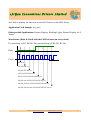
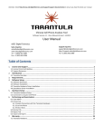
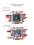
eSrijan Innovations Pr ivate Limited Linux Device Driver Kit User's Manual v1.4 Website: http://eSrijan.com Email: [email protected] 1 eSrijan Innovations Pr ivate Limited Background eSrijan Innovations Private Limited specializes in creation of innovative Automation Products & Solutions. eSrijan innovations are a combination of one or more of various Engineering streams, &/or Medical Systems, with applied Science & Technology. eSrijan Products are primarily targetted for the Indian majority. And, eSrijan Solutions are customized OEM products for specific customers. eSrijan Innovations, an Indian Institute of Science Alumni venture, was incorporated in February 2010. It is supported by a strong group of mentors including entrepreneurs and field experts. It is powered by a team, with average industry experience of more than 25 years. In product space, eSrijan is creating energy & education related products. In the solution space, it has its say in both rural and urban automation, ranging from daily chores to automotive. eSrijan is driving its solution development from its head-quarters in Bangalore, India. Contact Details Email: [email protected] Website: http://lddk.eSrijan.com/ Errata & Correspondence: For any errata, correction, feedback or any other correspondence regarding this document, feel free to contact us at the above mentioned contact details. Website: http://eSrijan.com Email: [email protected] 2 eSrijan Innovations Pr ivate Limited Revision History Revision Published Date th Description 1.0 13 March 2011 First version of the Linux Device Driver Kit's User Manual as per fw v1.0 1.1 5th April 2011 Updated as per fw v1.1. Control endpoint request CUSTOM_RQ_GET_MEM_SIZE added. USB driver samples renamed with name prefix 'uctl' changed to 'ddk'. Reference to serial_comm (minicom like application) added. LDDK block driver sample information added. 1.2 13th June 2011 Mentioned that 8-LED Array would work only with a direct serial port connection. Updated the various sample driver and application file names, as per the enhancements in the LDD templates. 1.3 1st August 2011 Updated as per fw v1.2. Default state of PGM LED has been changed to “on”, indicating a healthy firmware. 1.4 22nd May 2013 Corrected the website link. Added information on the Linux Device Driver Kit's USB vendor id & device id. Also added the information about the request type of the control requests. Website: http://eSrijan.com Email: [email protected] 3 eSrijan Innovations Pr ivate Limited Table of Contents Background...........................................................................................................................................2 Chapter 1: Introduction.........................................................................................................................5 Chapter 2: Sections of LDDK board....................................................................................................6 Chapter 3: LED-Array Control through DB9 connector......................................................................8 Chapter 4: LDD Kit as a USB device.................................................................................................10 Chapter 5: LDD Kit as a Block device...............................................................................................14 Website: http://eSrijan.com Email: [email protected] 4 eSrijan Innovations Pr ivate Limited Chapter 1: Introduction The Linux Device Driver Kit or LDDK (in short) is the first board of its kind based on popular Atmel's microcontroller ATMega16. It is a USB Device clocked at 16 Mhz with the free vendor ID 0x16C0, reserved by Objective Development (http://www.obdev.at), for shared usage for open hardwares. The product ID of LDDK has been chosen as 0x05DC, the one specified for vendor class devices. The LDDK is based on the design of DDK v1.1 and has been designed for both non-experienced users who make their first steps in the world of microcontrollers and professional programmers who search for a universal platform to write a Linux Device Driver. Features: 1) AVR uC based USB Device (clocked @ 16MHz) 2) With minimum of 16KiB Flash and 512B EEPROM 3) USB Powered - No additional power adaptor required 4) 8-LED Array for Character Device Driver programming through DB9 i/f 5) EEPROM accessibility as Character Device 6) Contains USB2Serial circuitry for USB Device Driver programming 7) Enabled with Block Device Driver programming over EEPROM/Flash 8) 2 line x 16 character driver controllable display interface 9) Self-upgradable for future new functionalities 10) And for an Electronics Hobbyist, it be additionally used for: Stepper Motor Control Upto 16 independent Digital I/O Controls Upto 8 independent ADC Inputs Upto 3 independent PWM Outputs (optional) Various automation using Sensors By custom programming as a uC-based device through standard HID i/f Website: http://eSrijan.com Email: [email protected] 5 eSrijan Innovations Pr ivate Limited Chapter 2: Sections of LDDK board 2 7 3 6 9 1 8 5 4 Website: http://eSrijan.com Email: [email protected] 6 eSrijan Innovations Pr ivate Limited 1. 2. 3. 4. 5. 6. Atmega16 Microcontroller – Brain of the LDDK Power LED – Glows to show the LDDK is powered up USB Cable connector – USB Device Port and Power Supply input B7:B0 – 8-LED Array indicating bits B7 to B0 (driven over DB9 connector) Female DB9 connector – For LED-Array & RS232 communication PGM – Toggle LED (controlled over USB). (In fw ver >= 1.2, its default state has been changed to “on” indicating a healthy firmware.) 7. PWR – Power Jumper (to be kept on left side for powering through USB) 8. RX – Serial Jumper (to be kept on right side for LED-Array communication and on left side for RS232 communication) 9. (Controller) Reset Switch Website: http://eSrijan.com Email: [email protected] 7 eSrijan Innovations Pr ivate Limited Chapter 3: LED-Array Control through DB9 connector LED-Array is a sequence of 8 LEDs, which are driven by serial data input from B7 to B0, one bit per clock. So, 8 -ve edge (high → low) clock transitions are needed to drive the complete 8-bit data onto the 8 LEDs. Configuration: RX jumper need to be on the right side. Connection: Connect the female connector of the serial cable to your PC's serial port and male connector of the serial cable to the LDDK's DB9 connector. Please note that the PC's serial port should be a direct one, not an indirect one like USB2SERIAL or so. Relevant DB9 Pin Connections: Male DB9 Pin No. USART Pin Meaning LED-Array Significance 3 Tx (Transmitter) Data (0: LED On; 1: LED Off) 4 DTR (Data Terminal Ready) Clock (High to Low: Shifts Data) Examples: 1) To glow B0 – Set USART “Tx” line low, and then send a “High” → “Low” signal over USART “DTR” line. Note that pulling “Tx” line low is not same as sending “0” on it, rather it setting the break. 2) To switch off B0 – Set USART “Tx” line high, and then send a “High” → “Low” signal over USART “DTR” line. Note that setting “Tx” line high is not same as sending “1” on it, rather it releasing the break (the default state of “Tx” line) 3) To glow B1 & switch off B0 – Set USART “Tx” line low, and then send a “High” → “Low” signal over USART “DTR” line. Then, set USART “Tx” line high, and then send a “High” → “Low” signal over USART “DTR” line. Driver Code Sample: led_board.c Explanation: This sample interfaces the LDDK as a character device interface Website: http://eSrijan.com Email: [email protected] 8 eSrijan Innovations Pr ivate Limited /dev/led0 to display the data sent as the ASCII value on the LED-Array. Application Code Sample: led_ops.c Other possible Applications: Pattern Display, Blinking Lights, Buzzer Display for 8 Teams. Waveforms: (Data & Clock with the LED bit states on every clock) For switching on B7, B6, B5, B4, and switching off B3, B2, B1, B0 Data Clock B0 is on B0, B1 are on B0, B1, B2 are on B0, B1, B2, B3 are on B0 is off. B1, B2, B3, B4 are on B0, B1 are off. B2, B3, B4, B5 are on B0, B1, B2 are off. B3, B4, B5, B6 are on B0, B1, B2, B3 are off. B4, B5, B6, B7 are on Website: http://eSrijan.com Email: [email protected] 9 eSrijan Innovations Pr ivate Limited Chapter 4: LDD Kit as a USB device LDDK's firmware version 1.0 and higher provides majorly 3 USB device functionalities. The most basic form of USB communication is through something called an endpoint. A USB endpoint can carry data in only one direction, either from the host computer to the device (called an OUT endpoint) or from the device to the host computer (called an IN endpoint). Endpoints can be thought of as unidirectional pipes. LDDK's firmware version 1.0 and higher provides 5 such endpoints for the various functionalities. The universal control endpoint 0,which is both IN & OUT. And 2 interrupt IN and 2 interrupt OUT endpoints. Configuration: RX jumper need to be on the left side (only for the USB to Serial communication). Connection: Connect the type A connector of the USB cable to your PC's USB connector and the type B connector of the USB cable to the LDDK's USB Device Port. Additionally for USB to Serial communication, connect the female connector of the serial cable to your PC's serial port and male connector of the serial cable to the LDDK's DB9 connector. Endpoint Details: 1. Control endpoint 0 – Commonly used for configuring the device, retrieving information about the device, sending commands to the device, or retrieving status reports about the device. Usually used for small control transactions. Every valid USB device has to have this control endpoint 0 that is used by the USB host controller to understand the device. For our LDDK, it is additionally used to: a) On/off the PGM LED (CUSTOM_RQ_SET_LED_STATUS: 1) b) Know the current status PGM LED (CUSTOM_RQ_GET_LED_STATUS: 2) c) Set the memory read offset (CUSTOM_RQ_SET_MEM_RD_OFFSET: 3) d) Get the memory read offset (CUSTOM_RQ_GET_MEM_RD_OFFSET: 4) e) Set the memory write offset (CUSTOM_RQ_SET_MEM_WR_OFFSET: 5) f) Get the memory write offset (CUSTOM_RQ_GET_MEM_WR_OFFSET: 6) g) Get the memory size (CUSTOM_RQ_GET_MEM_SIZE: 7) (Only in fw ver >= 1.1) The defines & numbers in () are the corresponding request numbers for the Website: http://eSrijan.com Email: [email protected] 10 eSrijan Innovations Pr ivate Limited vendor specific request type for the recipient device, typically denoted by the flags USB_TYPE_VENDOR | USB_RECIP_DEVICE. Additionally, the request numbers 1, 3, 5 are for OUT (USB_DIR_OUT), and 2, 4, 6 are for IN directions (USB_DIR_IN), respectively. For the OUT requests, the parameter is passed through the value field of the control request. For the IN requests, the data is received through the data field of the control request. The index field of control request is ignored for all our requests. For request CUSTOM_RQ_SET_LED_STATUS, a value of 0 switches off the PGM LED and a value of 1 switches it on. For request CUSTOM_RQ_GET_LED_STATUS, the current PGM LED status is available in the bit 0 of byte 0 of the data received – 0 for off and 1 for on. For requests CUSTOM_RQ_SET_MEM_RD_OFFSET and CUSTOM_RQ_SET_MEM_WR_OFFSET, value is the 16-bit memory offset to be set. For requests CUSTOM_RQ_GET_MEM_RD_OFFSET and CUSTOM_RQ_GET_MEM_WR_OFFSET, the 16-bit memory offset to be obtained through the byte 0 & byte 1 of the data received – byte 0 being the LSB and byte 1 the MSB. Driver Code Samples: ◦ For LED specific control commands: ddk_led.c, ddk_led.h, ddk.h ◦ For memory specific control commands: ddk_mem.c, ddk_mem.h, ddk.h Explanation: These samples provide the LDDK as auto-detected character device interfaces /dev/usb/ddk_led0 and /dev/usb/ddk_mem0, respectively. These interfaces provide various ioctl system calls to provide the above control endpoint request functionalities to the user space. Application Code Samples: ◦ For LED specific control commands: usb_ops.c ◦ For memory specific control commands: usb_mem.c Addendum: A single collated example driver made of ddk_usb.c, ddk_usb.h, ddk.h is also available, providing character device interface /dev/usb/ddk0. The corresponding application for this is usb_test.c. Interrupt IN endpoints transfer small amounts of data at a fixed rate every Website: http://eSrijan.com Email: [email protected] 11 eSrijan Innovations Pr ivate Limited time the USB host asks the device for data. Interrupt OUT endpoints transfer small amounts of data at a fixed rate every time the USB host sends the data to the device. Both these transfers are guaranteed by the USB protocol to always have enough reserved bandwidth to make it through. 2. Interrupt IN endpoint (MEM_EP_IN: 0x81): This is the endpoint to receive/read data from the memory (fw v1.0 supports only EEPROM) from the current memory read offset, which is incremented automatically by how many bytes have been read. A single read request has to be exactly of 8 bytes. The memory size supported is 512 bytes (0x200). Driver Code Sample: ddk_mem.c, ddk_mem.h, ddk.h Explanation: This sample provides the LDDK as a auto-detected character device interface /dev/usb/ddk_mem0. This interface provides the read system call to provide the above interrupt endpoint request functionality to the user space. Application Code Sample: usb_mem.c 3. Interrupt OUT endpoint (MEM_EP_OUT: 0x01): This is the endpoint to send/write data to the memory (fw v1.0 supports only EEPROM) starting at the current memory write offset, which is incremented automatically by how many bytes have been written. A single write request can be maximum of 8 bytes. The memory size supported is 512 bytes (0x200). Driver Code Sample: ddk_mem.c, ddk_mem.h, ddk.h Explanation: This sample provides the LDDK as a auto-detected character device interface /dev/usb/ddk_mem0. This interface provides the write system call to provide the above interrupt endpoint request functionality to the user space. Application Code Sample: usb_mem.c 4. Interrupt IN endpoint (SER_EP_IN: 0x82): This is the endpoint to Website: http://eSrijan.com Email: [email protected] 12 eSrijan Innovations Pr ivate Limited receive/read data from the serial port (DB9 connector of LDDK) through USB. A single read request has to be exactly of 8 bytes, though less than 8 bytes may be returned, which need to appropriately handled by the driver developer. Driver Code Sample: ddk_u2s.c, ddk_u2s.h, ddk.h Explanation: This sample provides the LDDK as a auto-detected character device interface /dev/usb/ddk_u2s0. This interface provides the read system call to provide the above interrupt endpoint request functionality to the user space. Application Code Sample: usb_ops.c, serial_comm.c 5. Interrupt OUT endpoint (SER_EP_OUT: 0x02): This is the endpoint to send/write data to the serial port (DB9 connector of LDDK) through USB. A single write request can be maximum of 8 bytes. Driver Code Sample: ddk_u2s.c, ddk_u2s.h, ddk.h Explanation: This sample provides the LDDK as a auto-detected character device interface /dev/usb/ddk_u2s0. This interface provides the write system call to provide the above interrupt endpoint request functionality to the user space. Application Code Sample: usb_ops.c, serial_comm.c Help: For this functionality to work properly, the RX jumper should be on the left side. In case, if it still gives problems, try reseting the micro-controller using the red “reset” button. Make sure that all the serial communication applications like serial_comm, minicom, gtkterm, hyper-terminal, ... are quit before trying this. NB All these USB related code samples must be tried mutually exclusively – meaning unload all others to try the next one. (Important !!!) Website: http://eSrijan.com Email: [email protected] 13 eSrijan Innovations Pr ivate Limited Chapter 5: LDD Kit as a Block device LDDK's firmware version 1.0 and higher provides 1 USB device functionality for supporting the Block device interface, namely through the endpoints MEM_EP_IN (0x82) and MEM_EP_OUT (0x01). These endpoints have been already explained in the previous chapter. See sections 2 & 3 for endpoint details. The same endpoints may be used to provide the LDDK as a block device interface. Connection: Connect the type A connector of the USB cable to your PC's USB connector and the type B connector of the USB cable to the LDDK's USB Device Port. Driver Code Sample: ddk_storage.c, ddk_storage.h, ddk_block.c, ddk_block.h Explanation: This sample provides the LDDK as a auto-detected block device interface /dev/ddk. This interface provides the block reads & writes to provide the above interrupt endpoints' requests functionality to the user space. Driver Code Reference: ram_block.c, ram_device.c, ram_device.h, partition.c, partition.h Explanation: This reference code interfaces the RAM as block device interface /dev/rb*, with partitioning. It may be used as a reference to provide the LDDK as a similar block device interface with partitioning. Recommended Applications: dd, cat, echo, od -t x1 Website: http://eSrijan.com Email: [email protected] 14