1
NEXT GENERATION ATMEL ATMEGA644
ATMEGA644 PROTOTYPE BOARD
A Design Project Report
Presented to the Engineering Division of the Graduate School
of Cornell University
in Partial Fulfillment of the Requirements for the Degree of
Master of Engineering (Electrical)
by
Nathan Isaac Chun
Project Advisor: Bruce Land
Degree Date: May 2010
Abstract
Master of Electrical Engineering Program
Cornell University
Design Project Report
Project Title:
Author:
Next Generation Atmel Mega644 Prototype Board
Nathan Isaac Chun
Abstract:
The next generation prototype ATmega644 board allows students
in ECE 4760 (Digital Systems Design Using Microcontrollers) to execute labs
with a minimum of overhead and unnecessary complexity in set-up. The legacy
system involves using a large development kit that requires obselete connections
and converters to connect to the computer. The proposed prototyping board has
a microcontroller to USB to PC interface to create a small, cheap, portable
system that very simply can be used with a solder-less breadboard for labs and
projects. The next generation prototype board involves PCB design and
production, and interface construction and testing in order to create a small
board that can be mass produced for future classes.
Report approved by
Bruce Land:________________________________________ Date: _____________
1
Executive Summary
The next generation Atmel ATmega644 prototype board described in this paper
has been designed with the Microcontrollers class at Cornell University (ECE
4760) in mind. The current situation does not allow students to easily work
outside of class due to restrictions on access to the relatively expensive
equipment. This device addresses this concern by providing students with an
inexpensive method of working on projects outside of class. This device provides
students with the flexibility to explore the projects and the material in a greater
depth. It makes executing projects easier and simpler by minimizing
unnecessary overhead in terms of complexity and difficulty, as well as lower
costs for the class to be run, as the equipment required will be simpler, cheaper,
and more accessible.
Throughout the several iterations of the design from circuit diagram to printed circuit
board, certain tests and verification were performed in order to gauge the performance
of the product. Functional tests allowed the design to proceed past the initial
prototyping stages. Speed tests showed that using MATLAB, a bit rate of 9,600 baud
can be achieved and speeds using HyperTerm can reach 57,600 baud. Operational tests
revealed weaknesses the intermediary prototypes that were barriers to one of the
critical aspects of the design: ease of use.
The final design provided a functional and flexible rapid prototyping platform based
on the Atmel ATmega644 microcontroller specifically designed for use by the students
of ECE 4760.
2
Problem
roblem
Design P
2.1
Overview
ECE 4760 at Cornell University is a microcontrollers class taught at Cornell
University using the Atmel ATmega series of chips. The typical development
environment utilizes the Atmel STK500, “a starter kit and development system
for Atmel’s AVR Flash microcontrollers” [4]. While this is a fully featured
development suite designed for use with Atmel’s entire line of microcontrollers,
it is also expensive, requiring that the development kits be used only in lab
under TA supervision.
The class work is almost completely based on projects and lab time is crucial to
the execution of the projects. Since the lab is only open for limited times due to
need of TA supervision, access to the equipment needed to complete the
assignments is limited, making it unnecessarily difficult for students to work on
the projects.
This paper addresses this concern by outlining the design for a small,
inexpensive rapid prototyping board that can be used to replace the larger and
more restrictive current setup.
2.2
System Requirements and Design Specifications
The board and interface design proposed must:
• Be intuitive to use
• Operate in a stable manner
• Be inexpensive
• Use off-the-shelf components
• Be able to be assembled by hand
• Allow for flexibility for use in rapid prototyping projects
3
Solution
3.1
Potential Solutions
Currently, there is a prototype board designed by Bruce Land that solves
some of the issues posed in the previous section, but its effectiveness is limited
by its reliance upon antiquated technology. This smaller prototype board uses
an RS—232 DE—9 serial interface to communicate with the PC. As most laptops
do no longer have a DE—9 port, more equipment is required to convert the serial
data to USB, which is a more popular standard. The design proposed in this
paper is heavily based on this design, using a USB interface instead of the older
RS—232.
Several chips are commercially available to convert an RS-232 signal to USB.
FTDI produces the FT232 and the FT245, Prolific produces the PL2303 and
the PL2313, Silicon Laboratories produces the CP2102 and CP2103.
Another possible solution to the interface problem uses onboard USB where the
microcontroller itself reads and writes directly to the data stream. V-USB is an
example of a piece of code that can be programmed into the chip to interface
with a USB port [11].
3.2
Selected Solution
The chip selected for use in the final design was the FT232RL, a USB to serial
UART interface chip in a SSOP—28 package. This solution was chosen for the
following reasons:
• It has been widely and successfully used in a variety of applications
• Its operation is well documented [2][6][10]
• There are many example circuits to use as references
• It comes in a manageable package (large enough for hand soldering)
An onboard USB solution was not selected because of the excess complexity
that the user may have to deal with, as well as the fact that the complicated
and multilayered interface would likely consume a good deal of memory and
speed in the microcontroller, a very large drawback to any solution.
4
Documentation
4.1
Design
The circuit design is heavily based on the interface used by the
ArduinoBoardMega [2], a system popularly used by hobbyists and designed
around the ATmega1280, a larger version of the ATmega644 used in this
project [3]. There were a few changes from the original Arduino design. The
reset hardware control line (RTS#) was disconnected since this design didn’t
need to incorporate the reset functionality. The LED status lights were removed
from the design to keep the layout small and compact. The ferrite bead on the
VCC line was ignored as the device did not need the extra noise protection as it
will primarily be used in environments where interference is minimal.
As discussed in more detail in section 4.3, the final design uses two power
supplies, the bus—power for the interface chip and a separate power supply for
the microcontroller, differing from the Arduino design where both the chip and
the microcontroller are on the same power line.
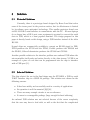
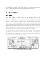
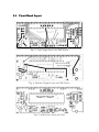
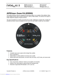
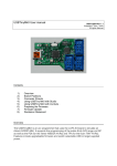
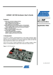
Fig. 1: Final Printed Circuit Board Design
The layout of the board is based on the current generation of ATmega644
prototyping boards designed by Bruce Land [9]. It contains a power socket and
voltage regulator to provide a regulated 5V power supply to the microcontroller,
a 16 MHz crystal oscillator, a test LED to demonstrate proper functionality, a
6-pin ISP programming header, the USB interface chip and a USB-B socket.
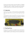
4.2
Implementation
The first circuit was built on a solder-less protoboard for initial functionality
testing and to decide whether or not to pursue the proposed design. Since the
design worked properly, the next step was to create a printed circuit board
layout.
The final product was designed in ExpressPCB’s layout software and fabricated
by ExpressPCB. The printed circuit board was then populated by hand with
header pins in each of the 36 pins lining the top of the board to allow the
protoboard to be plugged into a solder-less breadboard for easy use.
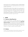
4.3
Major Design
Design Changes
Since this product is supposed to be designed for ease of setup and use,
accessibility was a critical factor in its production. The initial layout failed this
requirement as opening a serial connection to the board was complicated and
convoluted. While the connection is being opened, the microcontroller transmit
and receive pins must be in a quiescent state to avoid the computer interpreting
signals improperly; in one case, the USB serial interface to an ADC was treated
as a mouse, causing the cursor to jump wildly across the screen as the system
attempted to parse the data.
The first prototype required that the transmit and receive jumper pins be
disconnected and reconnected at specific points in the connection process, an
action judged to be unnecessarily complicated. The final revision addressed this
concern by isolating the power to the interface chip from the power to the
microcontroller, allowing each to be independently activated. This design
utilizes the regulated 5V supply on the USB bus line to power to the interface
chip, allowing the serial connection to be created by the interface program on
the PC while the microcontroller is unpowered and quiet.
5
Results
5.1
Comparison to Original
Original Expectations
According to the manufacturer, the FT232RL interface chip is capable of
operating at 3,000,000 baud [6]. During speed testing using the ADC UART
Interface Test Program [1], the data rates achieved were significantly lower.
HyperTerm was stable up to 57,600 baud and no higher while MATLAB was
operational at or below the default 9,600 baud rate. Possible reasons for these
shortcomings may be the fact that the overhead involved in reading the serial
input take too much time and allow the terminal’s input buffer to be
overwritten as it is being read resulting in invalid data acquisition.
5.2
Verification
In order to verify that the design is robust and works as expected, the system
was put through rigorous functionality, quality and operational testing.
The initial prototype board as described above was connected to a computer
and the interface was verified to work properly both in transmit and receive
modes. The microcontroller was programmed with the Interrupt—Driven UART
Test Program available on the ECE 4760 class website [7], running at the
default baud rate of 9,600. This program was designed to receive a serial input
from HyperTerm and transmit the appropriate response to the user at the
terminal. The design passed the test successfully and proceeded to the next
phase of testing.
As discussed in the previous section (5.1), speed tests were performed to
measure the speed of the interface.
The final phase of testing involved several iterations of the printed circuit board
to test the user interface aspect of the system and find out if there were any
barriers to properly and easily utilizing the design. As discussed above in
section 4.3, ease of setup and use determined certain design changes that
resulted in the final version submitted in this paper.
6
Acknowledgements
The author would like to thank Bruce Land, Senior Lecturer, Cornell
University, for his assistance, and Scott Coldren, Manager of Student Services,
Cornell University, for his support.
A
Appendices
A.1 Online Resources and References
[1] ADC UART Interface Test Program
http://courses.cit.cornell.edu/ee476/labs/s2010/lab4code/ADCtest.zip
[2] ArduinoBoardMega
http://arduino.cc/en/Main/ArduinoBoardMega
[3] Atmel ATmega644 Datasheet
http://www.atmel.com/dyn/resources/prod˙documents/doc2593.pdf
[4] Atmel STK500 Product Page
http://www.atmel.com/dyn/products/tools˙card.asp?tool˙id=2735
[5] ExpressPCB
http://www.expresspcb.com/
[6] FDTI FT232RL Datasheet
http://www.ftdichip.com/Documents/DataSheets/DS˙FT232R.pdf
[7] Interrupt—Driven UART Test Program
http://courses.cit.cornell.edu/ee476/labs/s2009/lab3code/SerialISRversion.zip
[8] MATLAB Serial Port Information Page
http://www.mathworks.com/access/helpdesk/help/techdoc/
matlab˙external/f38496.html
[9] Prototype Board for Atmel Mega644
http://www.nbb.cornell.edu/neurobio/land/PROJECTS/
Protoboard476/index.html
[10] SparkFun Electronics Breakout Board for FT232RL USB to Serial
http://www.sparkfun.com/commerce/product˙info.php?products˙id=718
[11] V-USB - A Firmware-Only USB Driver for Atmel AVR Microcontrollers
http://www.obdev.at/products/vusb/index.html
A.2
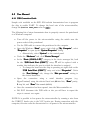
A.2 User Manual
A.2.1
A.2.1 USB Connection Guide
Sample code available on the ECE 4760 website demonstrates how to program
the chip to enable UART. To change the baud rate of the microcontroller,
change the #define UART_BAUD value in uart.c.
uart.c
The following list of steps demonstrates how to properly connect the protoboard
to a Windows computer:
• Turn off the power to the microcontroller using the switch near the
power socket of the protoboard
• Use the USB cable to connect the protoboard to the computer
• Open the Windows “Start”
Start” menu, right click on “My Computer”
Computer”, select
“Properties”
Properties” to open up the “System Properties”
Properties” dialog.
o Alternatively, select “System”
System” in the control panel
• Under the “Hardware”
Hardware” tab, click “Device Manager”
Manager”
• In the “Ports (COM & LPT)”
LPT)” category in the device manager list, look
for the “USB Serial Port (COM??)”
(COM??)” entry. ?? will be replaced with a
number that indicates the port to which the interface is assigned.
o To change the baud rate the chip is operating at, right click on the
“USB Serial Port (COM??)”
(COM??)” entry and select “Properties”
Properties”. Under
the “Port Settings”
Settings” tab, change the “Bits per second”
second” setting to
the desired baud rate.
• Open the connection using a serial interface program (e.g.
HyperTerminal) using the selected baud rate, 8 data bits, “None”
None” parity,
1 stop bit, and “None”
None” flow control. (8—N—1)
• Once the connection has been opened, turn the Microcontroller on.
• DO NOT disconnect the USB cable or else you will have to repeat the
steps to connect over again
NOTE: It is possible to bus—power the microcontroller by running a wire from
the USBVCC header pin to the VCC header pin. During connection with the
computer, this wire must be disconnected to cut power to the microcontroller.
A.2
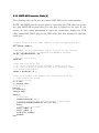
A.2.2 MATLAB Connection Guide [8]
The following code can be used to connect MATLAB to the serial interface.
NOTE: MATLAB must be opened prior to connecting the USB cable due to the
fact that MATLAB requires that it be the first to connect to the port. If you
receive an error when attempting to open the connection, unplug the USB
cable, restart MATLAB, plug in the USB cable, and then attempt to open the
serial port.
% Create serial object at COM?? (Replace ?? with the appropriate port
number)
SO = serial('COM??');
% OPTIONAL: Set the input buffer size to 32 bytes to only read the
%
more recent entries to compensate for MATLAB's overhead.
set(SO,'InputBufferSize',32);
% Open the serial object
fopen(SO);
% Read data from serial port
% '%s' can be replaced with any standard c formatting string
% '%s' reads an array of characters and can be parsed by index
% ex. hex2dec(readin(4:6))
readin = fscanf(SO,'%s');
% here is an example code snippet that continuously plots the
%
last hundred data points
% initialize arrays
x = 1:100;
y = zeros(1,100);
% set up plot
hold on
p = plot(x,y);
ylim([0 255]);
while(1)
% read input
readin=fscanf(SO,'%s');
% extract necessary data and concatenate to data arrays
y=horzcat(hex2dec(readin(11:12)),y(1:99));
x=x+1;
% update plot and redraw
set(p,'xdata',x)
set(p,'ydata',y)
xlim([x(1) x(100)])
drawnow
end
% Close the serial object
fclose(SO)
% Delete and clear the serial object variable
delete(SO)
clear SO
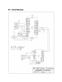
A.3
A.3 Circuit Schematic
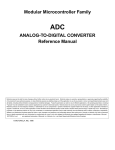
A.4
A.4 Circuit Board Layout
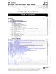
Fig. 3: Top Copper Layer and Silk Screen
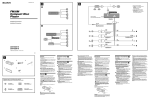
Fig. 4: Bottom Copper Layer and Silk Screen
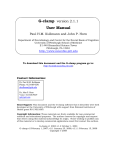
Fig. 5: Silk Screen, Pads and Vias