1
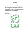
Switch-4X
Extended Version of the Switch-4
PC Board Revision 1
February 14, 2011
Instruction Manual
Durand Interstellar, Inc.
219 Oak Wood Way
Los Gatos, California 95032-2523
www.interstellar.com
tel: +1 408 356-3886, USA toll free: 1 866 356-3886
Table of Contents
Table of Contents.................................................................................................................i
Intended Use.......................................................................................................................1
Specifications......................................................................................................................2
Mounting.............................................................................................................................3
Programming.......................................................................................................................4
Wire Connections..............................................................................................................10
Testing...............................................................................................................................12
California Proposition 65 Warning...................................................................................13
Warranty............................................................................................................................14
i
Intended Use
The Switch-4X interface will allow up to four switch inputs to send commands to
a host device (such as a PC running ShowMan, a Mac running QLab a lighting
control board, a PLC, or other musical or digital equipment). The Switch-4
supports both MIDI and RS-232, but only one at a time.
Since the data sent by the Switch-4X has no error checking, it should not
be used to control anything that might be damaged or cause injury if the
wrong data is received.
The Switch-4X is designed to be continuously powered, typical power use is
about 1/10th of a Watt so it meets all energy conservation requirements.
This device complies with part 15 of the FCC Rules. Operation is subject to the
following two conditions: (1) This device may not cause harmful interference, and
(2) this device must accept any interference received, including interference that
may cause undesired operation.
The only user serviceable parts inside are the screw terminals and the
programming jumper. Re-attach the cover securely being careful to not bend the
LED. Never apply power with the cover removed.
The latest version of this manual, and any application notes are available from
our support site:
http://interstellar.com/support.html
All of our documentation is in PDF format. Download a free reader from:
http://www.foxitsoftware.com/pdf/reader/
or
http://www.adobe.com
All trademarks are the property of their owners and are used for reference only.
1
Specifications
•
•
•
•
•
•
•
•
•
•
•
•
•
•
•
Width: 3.5” (89mm) including mounting flanges
Height: 2.5” (64mm)
Thickness: 1” (25mm)
Mounting: Two 0.19” (4.8mm) diameter holes on 3” (76.2mm) centers.
Weight: 2oz (60gm)
Connections: Screw terminals and one internal jumper
Power supply: 9-24VDC, 50mA max (shorted output cable), normal draw
is about 10mA (varies slightly with output mode)
Environmental: 32-100° F (0-40° C), non-condensing humidity
Switch inputs: Four contact closure or logic level. Active LOW with internal
pullup resistors.
Debounce: user selectable (4 to 65mS) on both Open and Close.
Initial Delay: Switches are ignored for about 5 seconds after power up.
Data output: MIDI Note commands or RS-232 characters
Data Format: 8 data bits, no parity, timed to work with 1 or 2 stop bits
Output Levels: 0V and 5V, current limited. Polarity is programmable.
Number of times the programming may be changed: 10,000 or more
Note: The RS-232 specification calls for voltage levels of -12V to -3V for
“Mark” but except in very rare cases RS-232 receiver chips allow a “Mark”
to be as high as +0.8V. The Switch-4 uses 0V for “Mark” and should have
no problem working with all modern devices. If you have any concerns, you
may contact us for help in verifying the levels needed for your application.
TTL levels are 0-5V on input and output.
MIDI operation is fully compliant with the specification and recommended
practices.
2
Mounting
The Switch-4X is designed to be mounted to a wall or inside another enclosure
such as a kiosk. It is intended for indoor use but may be used outdoors if
protected from moisture and excessive heat/cold.
When mounted to a vertical surface, the screw terminals (J1 in the illustration
below) should be on the bottom. This lets the wires hang freely and also
prevents any foreign material from falling in through the slot in the box.
The first two pins of J2 are used for the programming jumper. The rest of J2 is
only used for initializing the Switch-4X during manufacture, it is not used in
normal operation except in some custom applications.
Be sure to allow room to remove the cover in case you need to remove or add a
wire in the future or change the programming. Support the wires to the mounting
surface as needed.
3
Programming
The Switch-4X needs to be programmed before use and this requires a little
planning and work on your part. You should read through this whole section
before starting to make sure you have everything you need. If you need help,
feel free to ask us.
The first thing you will want to do is download our Switch-4X Setup Utility from
our Support page. This requires Open Office software to open and run. If you
don't have a copy of Open Office, you may download one for free (Windows, OS
X, Linux) from:
http://www.openoffice.org/
This program is free software: you can redistribute it and/or modify it under the
terms of the GNU General Public License as published by the Free Software
Foundation, either version 3 of the License, or (at your option) any later version.
This program is distributed in the hope that it will be useful, but WITHOUT ANY
WARRANTY; without even the implied warranty of MERCHANTABILITY or
FITNESS FOR A PARTICULAR PURPOSE. See the GNU General Public
License for more details.
You should have received a copy of the GNU General Public License along with
this program. If not, see <http://www.gnu.org/licenses/>.
When you open the utility you may be asked to enable macros, click on the
Enable Macros button:
You should now see a screen something like the following (if you've previously
saved the utility with your data in it, it will open with that data instead of the
sample data):
4
You will be filling in the boxes with the white background and the built-in macros
will convert that to the hex programming data on the right.
If you already have a data file on disk, see below on reading it in.
The first 8 boxes are marked "Switch 1 On", "Switch 1 Off", etc. This is where
you will enter the data you wish sent out when that action happens (switch
opening or closing). If you don't want anything to happen on a particular action
then leave that box empty (make sure there aren't any blank spaces in the box or
they will be sent).
If you need to send non-printable characters such as MIDI data you may enter
them as either hex or octal data. For standard control characters you may also
use standard C shortcuts.
\n = NL/LF (New Line/Line Feed)
\t = HT (Horizontal Tab)
\v = VT (Vertical Tab)
\b = BS (Back Space)
\r = CR (Carriage Return)
\f = FF (Form Feed)
\a = BEL (Audible Alert)
\xAB = hex data entry where AB is any two digit hex data (00 to FF)
\123 = octal data entry where 123 is any three digit octal number (000 to 377)
\\ = the character \
Each of the 8 output strings may be up to 30 bytes long. A byte is an individual
character such as the letter A or a single non-printable character such as \xAB.
You may click the "Update Hex Data" at any time while entering data and if there
5
are any problems they will be marked with a red background. Note that the byte
count for each entry is shown in column C.
Once you have all 8 output strings the way you want them, you need to set up
some technical parameters. The first one is Mark. This is the condition of the
output pin during idle times. For MIDI output and normal TTL output you would
set this to 1 (one), for inverted TTL and RS-232 set this to 0 (zero).
Next is the debounce setting, this determines how long the input switches have
to be stable before a change is acknowledged. For most applications you can set
this to 5 and never worry about it again. If you find you're getting multiple
activations for one switch press, then you need to increase the debounce setting.
The maximum setting is 16 which is about 0.065 seconds. If you're missing quick
switch taps, then you need to decrease the setting. The minimum setting is 1
which is about 0.004 seconds.
Now comes the baud rate (bits per second). For MIDI always set this to 31250.
For RS-232 and TTL systems you'll need to check what the receiving equipment
is expecting. The allowed range is 110 to 38400 including all normal and odd
possibilities. The baud clock is derived from a 16MHz counter so there should be
very little error for any baud rate.
At this point you'll want to make sure you've pressed RETURN or clicked on a
blank gray cell to make sure your change is recorded and then press the
"Update Hex Data" button. Fix any errors detected and repeat until there are no
red cells.
If you wish you may save the utility and all data you've entered by clicking on File
on the top tool bar and then Save As. Chose a different name so you know this
is your data.
Now you will want to save all this data in a text file on your system. The file may
have any name you wish but an ending of .txt may make it easier to send to the
Switch-4X depending on your serial terminal software. If you just enter the name
with no path the file will be saved in the same folder that the utility is stored in. If
you enter a folder and then a file name such as shown above, then the file will be
stored in that folder. After entering the file name, make sure to press RETURN or
click on the gray area, then click the Save/Write button. If the file exists you'll be
asked if you want to replace it. If it doesn't exist, it will be created.
You may now exit the utility, saving a copy with your data if you wish.
Reading/Loading data files
If for some reason you wish to load a data file to either view it or make changes,
then the only box you need to fill in is the File Name. Press RETURN or click on
a gray box, then click the Load/Read button. The file will be read and any errors
reported. Also the hex data will be converted back to fill in the other boxes. If the
data file contained MIDI data or other non-printable characters, then the
6
reconstructed strings may look a bit different from what you originally entered.
This is because during the reconstruction of these strings anything that is a
printable character is shown as that character, even for MIDI data. Also any nonprintable characters are show as either the standard C shortcut or hex data. This
should not change what's really sent out but may make your data strings look
odd.
You may now edit the reconstructed data and save as you wish.
Connecting the USB Cable
Now that you have a data file you need to be able to send that to the Switch-4X.
This requires the use of a 5V TTL serial connection, the recommended FTDI
cable provides this and works with Windows, OS X, and Linux systems. You may
also make your own cable if you wish, contact us for more information.
The FTDI cable has six wires, you will not be using the brown and green ones,
tape the ends of these to keep them from shorting.
Turn off the power supply for the Switch-4X and remove any wires connected to
the Switch-4X terminals marked Shield, D+, D-, and SW1. You may leave SW24 connected if you wish.
If not already connected, attach the positive (+) wire from your DC power supply
to the terminal marked 9-24VDC. Next connect the negative (- or ground) wire
from the supply to the GND terminal. Do not turn on the power yet.
Attach the black wire (ground) from the FTDI cable to the SHIELD terminal.
Attach the red wire (+5V) to the D+ terminal.
Attach the yellow wire (RXD) to the D- terminal.
Attach the orange wire (TXD) to the SW1 terminal.
Install a jumper across pins 1 and 2 of J2 on the Switch-4X board. If the jumper
has been lost, short these two pins together with any handy piece of wire.
Turn on the DC power supply, the Switch-4X LED should come on and after
about 5 seconds start blinking to indicate its in programming mode.
Plug the FTDI cable into your computer, Windows will probably ask you to allow
it to install software, tell it to go ahead (you may need to be connected to the
Internet). OS X and Linux generally have the software already installed and won't
give any notice.
If you want/need to download the latest drivers for your computer, you will find
them here:
http://www.ftdichip.com/FTDrivers.htm
7
You will need a serial terminal program for your computer (this is NOT the
Terminal program in OS X and Linux) to communicate with the Switch-4X. Older
versions of Windows came with Hyperterm, but that has been removed from
newer versions. We have CoolTerm for Windows and OS X on our Support page
for free download. For Linux we recommend GtkTerm which is available for most
versions of Linux from the usual sources. You may use any other terminal
program you wish as long as it can send and receive text files (possible by cut
and paste).
Start up your serial terminal program and have it connect to the new serial port
created when you plugged in the FTDI cable. You'll need to set the baud rate to
300, 8 data bits, no parity, 1 stop bit, no flow control, and local echo (optional).
An example from CoolTerm for Windows is below:
Press the RETURN/ENTER key a couple of times and you should receive the
character > as a prompt.
There are only only two commands available, R for Read current programming
and W for erase memory and install new programming. If you enter any other
command you will receive the character ! as an error indicator.
Try typing R (upper or lower case is ok) and you should get a block of hex data.
Depending on your terminal program, it may be single or double space. Example
of the screen while it's still receiving:
8
You may save this file to your disk if you wish to load it into the setup utility or
simply to clone this Switch-4X. Don't worry about the line length being different or
any double spacing, that will all be ignored when reading the file.
If you've gotten this far, you may now upload your new data file. Enter a W, this
will erase all memory and return the character # as a prompt. In CoolTerm click
on Connection in the tool bar and then choose Send Text File. Browse to where
you saved the data file from the setup utility and choose it. Sending will take
what seems like a long time to anyone used to modern Internet speeds. When it
is done you should receive an OK and a new prompt or two:
If you receive an error indicator (the character !), you may try again. If you
continue having trouble, feel free to contact us for assistance.
Close the serial terminal program, unplug the FTDI cable, turn off the DC power
supply. Then remove the jumper on J2 and the FTDI cable connections. Proceed
on to the next section, the Switch-4X is now ready for your application.
9
Wire Connections
If possible, connect all the wires before mounting the Switch-4X, this will make it
easier to get the wires into the screw terminals. Remove the cover being careful
to not bend the LED. Refer to the illustration above when connecting wires.
•
•
•
•
•
•
•
Make sure to not leave any loose pieces of wire or other foreign material
inside the Switch-4, a short could destroy the device.
Your DC power supply should have two wires, a positive and a negative or
ground. Connect the positive wire to the terminal marked “9-24VDC” and
the negative wire to the terminal marked “GND”. The Switch-4 is protected
from reverse polarity, so if you're not sure which wire is which you may
apply power at this point. If the LED doesn't come on within a couple of
seconds, turn off the power and reverse the wires.
With the power off, continue making connections.
The switch inputs are pulled up to 5VDC with 10KΩ resistors. If you are
using buttons, they will often be normally open (NO) momentary push
buttons. If using other types of switches, you only need single pole single
throw (SPST) but almost any type can be used by leaving unused
connections open. Very large switches intended for high current may be
electrically noisy and may need a capacitor across them to prevent
multiple detections. Contact us if you need any help with switches.
If using solid state devices (light beam sensors, motion sensors, etc.) you
may use ones with contact closures, open drain or open collector
transistor outputs, or logic levels (3V to 5V levels will work). Other types of
solid state devices may need a resistor added, please contact us for
assistance.
Switch #1 connects between the terminal marked “SW1” and either the
terminal marked “COM” or the “GND” terminal (power supply ground).
Switches 2-4 connect in the same fashion. Any unused inputs should be
left open (no connection).
MIDI Connections
• Your MIDI cable should have two or more insulated wires and a bare
shield wire which may also connect to pin #2 of the MIDI plug.
• Connect the SHIELD wire (and the pin #2 wire, if there is one) to the
terminal marked “SHIELD”.
• The “D+” terminal connects to pin #4 of the MIDI plug.
• The “D-” terminal connects to pin #5 of the MIDI plug.
RS-232 Connections
• RS-232 cables have two different pinouts called DCE and DTE. You must
determine the proper pinout for the equipment you are using.
• Connect the GROUND pin (typically pin 5 of a 9 pin connector) to the
SHIELD terminal.
• Connect the RX pin (typically pin 2 of a 9 pin connector intended to plug
10
•
•
into a PC) to the “D-” terminal. RX refers to your equipment, it's the pin
your equipment expects to receive data on.
If you have any other pins (possibilities are DCD, DTR, DSR, RTS, CTS,
RI) that need to be held at “Space” for your application, connect them to
the “D+” terminal.
All unused pins should be left open, tape wire ends to prevent shorts.
TTL Connections
• Connect the GROUND wire to the SHIELD terminal.
• If your interface has a 5V input or output, connect it to the D+ terminal
• Connect the RX wire to the “D-” terminal. RX refers to your equipment, it's
the pin your equipment expects to receive data on.
• All unused wires should be left open, tape wire ends to prevent shorts.
• Note that TTL may require either a 1 or 0 for Mark, see your equipment or
try one, then the other.
• Not recommended for 3.3V interfaces unless they are 5V tolerant.
11
Testing
Check that the jumper on J2 has been removed and there are no pieces of wire
or other foreign material inside the enclosure and then replace the cover. Be
careful to not bend the LED, it is supposed to fit into a hole in the lid.
Turn on the DC power and note that the Status LED comes on in about 1
second. You may also turn on whatever device is receiving the MIDI/RS-232/TTL
data.
Wait 5 seconds or more for the Initial Delay to complete. This delay is to let your
system stabilize after power up with no false commands. During this time any
switch changes are ignored and no commands will be sent.
If the LED starts blinking rapidly, it means either the jumper was left on J2 or the
memory failed its self test. If the jumper is not installed, try loading the program
in again. If you continue having trouble, please contact us.
Now one at a time operate each switch, note that the Status LED blinks off once
for each time any switch changes state (once for opening and once for closing).
If you see multiple blinks instead of just one, it means your switch is bouncing
longer than the debounce time. This is often caused by a dirty or noisy switch,
cleaning the contacts may very well fix this. If you can't clean the switch or it is a
type that has a very noisy contact, you can try increasing the debounce time in
the setup.
If you haven't already, turn on the device that is to receive the data and verify
that you are receiving the appropriate commands.
12
California Proposition 65 Warning
The following information is required by the State of California's Safe Drinking
Water and Toxic Enforcement Act of 1986, or Proposition 65. This California
regulation does not address safe levels, anything detectable at any level counts;
therefore, even trace amounts of the chemicals included on Proposition 65's list
of chemicals known to the State of California to cause cancer or reproductive
toxicity must be noted with the "Safe Harbor" wording. A “Green”, “lead free”
and/or RoHS device will probably still have detectable quantities of some
chemical on this list.
WARNING: This product contains lead and/or other chemicals known to the State
of California to cause cancer and/or birth defects and/or other reproductive harm.
California Proposition 65 Warning
13
Warranty
Durand Interstellar, Inc. warrants this product to be free from manufacturing defects in
original material, including original parts, and workmanship under normal use and
conditions (“manufacturing defect”) for a period of one (1) year from date of original
purchase. A charge will be made for repairs not covered by the warranty.
Should service become necessary, contact Durand Interstellar, Inc. for return
authorization and then:
•
•
•
Pack the unit in a well-padded corrugated box
Enclose a copy of your proof of purchase, if you are not the original
purchaser
Ship the unit prepaid via an insured carrier
NOTE: This warranty is void if the product is:
•
•
•
Damaged through negligence, misuse, abuse, or accident
Modified or repaired by anyone other than Durand Interstellar, Inc.
Damaged because it is improperly connected to equipment of other
manufacturers or through the failure of other equipment
NOTE: This warranty does not cover:
•
•
•
•
•
•
Damage to or caused by equipment connected to the product
Cost incurred in the shipping of the product to Durand Interstellar, Inc.
Damage or improper operation caused by customer abuse, misuse,
negligence, or failure to follow operating instructions
Ordinary adjustments to the product which can be performed by the
customer as outlined in the instruction manual
Improper operation caused by software written by any third party
Damage costs beyond the original purchase price of this product.
ANY APPLICABLE IMPLIED WARRANTIES, INCLUDING THE WARRANTY OF
MERCHANTABILITY, ARE LIMITED IN DURATION TO THE PERIOD OF THE
EXPRESSED WARRANTY AS PROVIDED HEREIN BEGINNING WITH THE DATE OF
ORIGINAL PURCHASE AT RETAIL, AND NO WARRANTIES, WHETHER EXPRESS OR
IMPLIED, SHALL APPLY TO THE PRODUCT THEREAFTER. DURAND INTERSTELLAR,
INC. MAKES NO WARRANTY AS TO THE FITNESS OF THE PRODUCT FOR ANY
PARTICULAR PURPOSE OR USE.
UNDER NO CIRCUMSTANCES SHALL DURAND INTERSTELLAR, INC. BE LIABLE FOR
ANY LOSS, DIRECT, INDIRECT, INCIDENTAL, SPECIAL, CONSEQUENTIAL DAMAGE ,
OR PATENT ISSUES ARISING OUT OF OR IN CONNECTION WITH THE USE OF THIS
PRODUCT.
THIS WARRANTY IS ONLY VALID IN THE UNITED STATES OF AMERICA. THIS
WARRANTY GIVES YOU SPECIFIC LEGAL RIGHTS. HOWEVER, YOU MAY HAVE
OTHER RIGHTS WHICH MAY VARY FROM STATE TO STATE. SOME STATES DO NOT
ALLOW A LIMITATION ON IMPLIED WARRANTIES OR EXCLUSION OF
CONSEQUENTIAL DAMAGE, THEREFORE THESE RESTRICTIONS MAY NOT APPLY
TO YOU.
14