1
USER MANUAL
A C T I V E TO PASSIVE CONVERTER
Requirements A
Keyboard functions A
Serial interface A
PC and graphics card
Projectors
Screen
Polarizing filters
Viewing glasses
.1
.2
.3
.4
.5
Setup procedure B
Connecting projectors
Connecting the PC
Aligning the projector
Setting up linear polarizing filters
Enabling the stereo software
Connect the stereo sync cable
.1
.2
.3
.4
.5
.6
Eyestrain C
Checking left and right image
Software parameters
Wrong setup of polarizing filters
Color- or brightness-differences
in projectors
Moving objects
.1
.2
.3
.4
----.5
Remote controlling D
LED indicators
Standby button
Toggle button
Right black button
User button
Menu button
Cursor buttons
.1
.2
.3
.4
.5
.6
.7
On Screen Display B
Source Setup
Stereo Setup
Preferences
Advanced
Info
Changes Done
.1
.2
.3
.4
.5
.6
Serial commands C
Summary
The help command
Topics
Commands
Linking of units
.1
.2
.3
.4
.5
Technical information D
Different types of picture signal
Different types of stereo syncs
Different types of stereo sync
connectors
Left/right sequence in frame
sequential stereo
Handling of sources
.1
.2
.3
----.4
.5
more information on previous page
more information on next page
more information on both previous and next page
highly important information
note
more information available elsewhere
Connection .1
Setting up HyperTerminal .2
Setting up other systems .3
Firmware upgrade B
Using Windows .1
Using non-Windows terminal .2
Connectors C
VGA input
Monitor redraw
Power input
Stereo sync input
Stereo sync output
Serial plug 1
Serial plug 2
DVI-D left and right output
VGA left and right output
Serial RS-232 cable
.1
.2
.3
.4
.5
.6
.7
.8
.9
.10
Technical specification D
Functions
Dimensions
Compatibility
Inputs
Outputs
Supplied material
.1
.2
.3
.4
.5
.6
Appendi xes
Part III
Usi ng the AP-convert er
Part II
Setti ng up the AP-co nver te r
Part I
Requirements A
PC and graphics card .1
Projectors .2
PC and graphics card
Screen .3
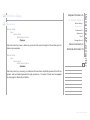
To run stereo using the AP-converter you need a frame-sequential stereo source, like a computer with a stereo-capable graphic card.
Polarizing filters .4
If you have a stereo-capable graphics card, you need to enable the stereo (some refer to it
as quad buffer). For a PC, this is usually done in the Display Properties.
Setup procedure B
Any kind of stereo signal running as active stereo (shutter glasses) will be accepted by
the AP-converter.
See www.stereographics.com for a list of stereo-capable graphics cards
Projectors
You need two projectors to display stereo.
Viewing glasses .5
Eyestrain C
Remote controlling D
S e t t i n g u p t h e AP - c o nve r t e r
A Requirements
To get the most out of your AP-converter, the projectors should support the maximum
resolution of your AP-converter.
Also see chapter C.4 (Eyestrain/Color or brightness differences in projectors).
You need; a frame-sequential
stereo source, a stereo-capable graphic card and two projectors.
The AP-converter supports resolutions up to 1280x1024.
For the latest information and
related url links please visit
our technical support pages
at www.christiedigital.com
copyright Christie 2002.06
- 3 -
Requirements A
PC and graphics card .1
Projectors .2
Screen
Screen .3
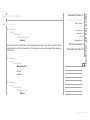
You need a screen with a non-depolarizing surface. Silverscreens and many rear-projection
screens have this quality.
Polarizing filters .4
Ordinary white screens or white walls do not have a non-depolarizing surface and may
not be used.
Setup procedure B
For more information on recommended screens go to http://www.stewartfilm.com
Polarizing filters
You need to place a polarizing filter in front of the lens of both projectors. This is done by
using the provided filters and filter stand.
There are two kinds of polarizing filters, the linear (most common) and circular. The provided
filters are of the linear type.
Viewing glasses .5
Eyestrain C
Remote controlling D
S e t t i n g u p t h e AP - c o nve r t e r
A Requirements
The filters need to be placed at the correct rotational angle, as described in chapter B.4
(Setup procedure/Setting up linear polarizing filters).
CAUTION! The filters can easily become distorted or gain hot spots if overheated. Max
temperature for filters is 75 degrees Celcius. Precautions should be taken to ensure
proper ventilation. Filters should be considered as a replacable item.
You need; a screen with
non-depolarizing surface, two
polarizing filters and a filter
stand.
The filter stand and two filters
are bundled with the AP-converter.
For the latest information and
related url links please visit
our technical support pages
at www.christiedigital.com
copyright Christie 2002.06
- 4 -
Requirements A
PC and graphics card .1
Projectors .2
Viewing glasses
Screen .3
If you need replacement filters visit our web page www.christiedigital.com
You need to use a pair of polarizing viewing glasses that match the polarization type of your
polarizing filters.
There are 10 pairs of glasses delivered with each AP-converter. These match the included
polarizing filters. You may use other viewing glasses as long as they match the polarization
filters in use.
The polarization of your viewing glasses must match the polarization of your polarization
filters.
If you require more pairs of viewing glasses visit our web page www.christiedigital.com
You need; a pair of polarizing
viewing glasses that match
the polarization of your polarization filters.
The AP-converter comes with
10 pairs of glasses. These
glasses match the linear polarization of the polarization filters.
Polarizing filters .4
Viewing glasses .5
Setup procedure B
Eyestrain C
Remote controlling D
S e t t i n g u p t h e AP - c o nve r t e r
A Requirements
For the latest information and
related url links please visit
our technical support pages
at www.christiedigital.com
copyright Christie 2002.06
- 5 -
Requirements A
Setup procedure B
Connecting projectors
Connecting projectors .1
Connecting the PC .2
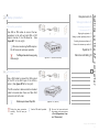
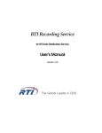
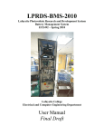
Use VGA or DVI cables to connect the two
projectors to the left and right VGA or DVI
output channel of the AP-converter. (See
figure B.1-1 on the right).
Aligning the projector .3
Setting up linear polarizing filters .4
Enabling the stereo software .5
Connect the stereo sync cable .6
We recommend using the DVI output on
the AP-converter wherever possible.
TheDVIsignalhasrestrictionsregarding
cable length.
Eyestrain C
figure B.1-1 (DVI and VGA out)
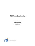
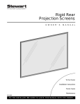
Connecting the PC
Use a VGA cable to connect the VGA output
of the PC to the VGA input of the AP-converter. (See figure B.1-2 on the right).
Remote controlling D
S e t t i n g u p t h e AP - c o nve r t e r
B Setup procedure
The AP-converter is delivered with a standard
cable to be used when there are 15pin VGA
connectors at both ends.
Notallcomputershavea15pinVGA
Follow the setup procedure
carefully. This will save you
time.
Use the DVI cable if possible.
figure B.1-2 (VGA in)
You can find more technical
information on the connectors
in Part III (Appendixes), chapter C (Connectors).
copyright Christie 2002.06
- 6 -
Requirements A
Setup procedure B
Connecting the PC
Connecting projectors .1
connector. Some other popular connectors are SUN type 13W3 and SGI type 13W3.
These require an adapter or a special cable to connect to the AP-converter.
Note that SGI and SUN have different pinout for 13W3 connectors.
Connecting the PC .2
Aligning the projector .3
Setting up linear polarizing filters .4
Enabling the stereo software .5
Connect the stereo sync cable .6
Eyestrain C
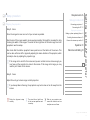
Aligning the projectors
Remote controlling D
To get the highest possible stereo image quality, you need to align the two projectors to
display their picture onto the exact same area. Although it may be difficult to get 100% alignment, you will still be able to see stereo even if the projectors are not completely aligned.
Properly aligned projectors enable you to read 2d details without using viewing glasses
or having to black out one of the channels.
To align the projectors you need to get a test image with a cross-hatched geometry pattern.
If you are using MS Windows you may download the freeware `ntest´ monitor testing utility
(© Nokia Monitors) and run the geometry test.
S e t t i n g u p t h e AP - c o nve r t e r
B Setup procedure
The `ntest´ and test patterns can be found on our technical support pages at
www.christiedigital.com.
Correct setup gives optimal
image quality and minimal eyestrain.
Better alignment gives less
eyestrain and distortions.
Useful downloads are available from our technical
support pages at
www.christiedigital.com
copyright Christie 2002.06
- 7 -
Requirements A
Setup procedure B
Aligning the projectors
Connecting projectors .1
Connecting the PC .2
To set up your projectors, follow the steps below carefully:
Aligning the projector .3
Setting up linear polarizing filters .4
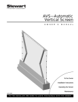
Step 1. Placement of projectors
Enabling the stereo software .5
Place the projectors at an appropriate distance from the
screen. Depending on your projectors and screen, this
might be between 3 - 6 meters.
Connect the stereo sync cable .6
figure B.3-1 (front view)
Remote controlling D
The projectors need to be stacked on top of each other. (See
figure B.3-1 and figure B.3-2 on the right). Try to align the
projectors in such a way that they are perfectly on top of
each other, and that they are at the same angle for all axes.
Ifyourprojectorshavenolens-shift,youneedtoposition
the lower projector to point slightly up, and the upper
slightly down. (See figure B.3-3 on the right).
it.
figure B.3-2 (side view)
Do not use digital keystone correction if you can avoid
Now; power up the projectors. You should be able to see
images on both projectors. If they are not already aligned,
two images will be visible superimposed on each other.
The two projectors should be
aligned at the same angle at
all axes.
A projector rack is not
required, but may be useful.
Eyestrain C
S e t t i n g u p t h e AP - c o nve r t e r
B Setup procedure
figure B.3-3 (no lens-shift)
Information on available racks
can be found on our technical support pages at
www.christiedigital.com
copyright Christie 2002.06
- 8 -
Requirements A
Setup procedure B
Aligning the projectors
Connecting projectors .1
Connecting the PC .2
Step 2. Zoom
Aligning the projector .3
Setting up linear polarizing filters .4
Zoom the images to cover as much of your screen as possible.
Enabling the stereo software .5
Also the size of the image needs to be as equal as possible. Normally this is easiest to do by
checking the width of the images. The outer left and right lines of the test image from both
projectors need to overlap.
Also check that the bottom projector’s lower pixel line is at the bottom of the screen. This
can be done with lens shift or physically adjusting the beam direction of the projector, which
normally is done by adjusting the projector legs.
If the image is too small for the screen and you are not able to zoom close enough, you
may have put the projector too close to the screen. If the image is too large, you may
need to put it closer to the screen.
Step 3. Focus
Connect the stereo sync cable .6
Eyestrain C
Remote controlling D
S e t t i n g u p t h e AP - c o nve r t e r
B Setup procedure
Adjust Focus to get a clear image on both projectors.
If you have problems focusing, the projectors may be too close or too far away from the
screen.
Follow the alignment steps
carefully.
The outer left and right lines
of the two test patterns need
to overlap.
Refer to your projector user
manual for directions on how
to adjust zoom and focus.
copyright Christie 2002.06
- 9 -
Requirements A
Setup procedure B
Aligning the projectors
Connecting projectors .1
Connecting the PC .2
Step 4. Beam alignment
Aligning the projector .3
Make the vertical edges overlap by shifting the upper or lower projector physically sideways,
forward or backward.
Setting up linear polarizing filters .4
Enabling the stereo software .5
Connect the stereo sync cable .6
Eyestrain C
Step 5. Lens shift
Now adjust the lens shift of the upper projector until the image overlaps the image from the
lower projector perfectly.
If your projectors do not have a lens shift function you must do this by physically adjusting
the beam direction of the projector. This can normally be done by adjusting the projector
legs.
Step 6. Fine-tuning
If you are not satisfied with the result, go back to Step 1. Placement of projectors and finetune the setup.
For optimal stereo image quality fine-tune your setup.
The lens shift function is not
required, but is helpful when
aligning the projector beams.
Remote controlling D
S e t t i n g u p t h e AP - c o nve r t e r
B Setup procedure
If you have any problems,
please refer to our technical
support pages at
www.christiedigital.com.
copyright Christie 2002.06
- 10 -
Requirements A
Setup procedure B
Setting up linear polarizing filters
Connecting projectors .1
Connecting the PC .2
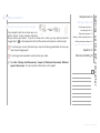
WARNING:Donotlookdirectlyintothe
beam of the projector! That may cause
damage to your eyes!
Aligning the projector .3
Setting up linear polarizing filters .4
Enabling the stereo software .5
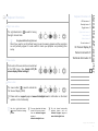
It is important to get the left image at the left
eye. To do this, press the `right black button´
and the projector showing the right eye
will go black. Now put on a pair of polarizing
glasses, and hold one of the polarizing filters
in front of the projector that is not blacked
out. Rotate the filter until the image seen
through the right eye appears as black as
possible. (See figure B.4-1 on the right).
Connect the stereo sync cable .6
Eyestrain C
Remote controlling D
figure B.4-1 (rotation)
Itisimportantthatyourheadandglasses
are at a normal viewing position horizontally when doing this.
When the correct angle is found, place the
filter into the filter stand at that angle, in
such a way that it covers the projector light
beam. (See figure B.4-2 on the right).
S e t t i n g u p t h e AP - c o nve r t e r
B Setup procedure
figure B.4-2 (filterstand with filters)
Do the same with the other filter (using the
WARNING:
Do not look
directly into the beam of the
projector! That may cause
damage to your eyes!
You must hold your head
(glasses) at a normal viewing
position while checking the
image.
copyright Christie 2002.06
- 11 -
Requirements A
Setup procedure B
Setting up linear polarizing filters
same projector), but now the images should appear black on the left eye. When the correct
rotational angle is found, place the filter into the filter stand making sure it covers the other
projector light beam.
Connecting projectors .1
Connecting the PC .2
Aligning the projector .3
Setting up linear polarizing filters .4
Enabling the stereo software .5
Press the `right black button´
again to switch on both projectors, and check that the left
eye sees one projector image, and the right eye sees the other image.
Also see chapter C.3 (Eyestrain/Incorrect setup of polarizing filters).
Enabling the stereo software
In addition to enabling the stereo on the
graphic card, you normally in OpenGL applications also have to enable the stereo in the software you are using. You may also need to
adjust your stereo settings, such as eye distance and focus point.
Connect the stereo sync cable .6
Eyestrain C
Remote controlling D
S e t t i n g u p t h e AP - c o nve r t e r
B Setup procedure
Correct setting of eye distance and focus point will optimize image quality and minimize
eyestrain.
Please refer to your graphic cards manual for instructions on how to adjust the stereo
settings.
Remember to enable the
stereo in the software, as well
as on the graphic card.
copyright Christie 2002.06
- 12 -
Requirements A
Setup procedure B
Connect the stereo sync cable (if possible)
If your graphic card has a stereo sync connector, connect it using a stereo cable that
fits your stereo sync output. If you do not have such a cable, you may need to press the
`toggle button´
on the keyboard to tell the AP-converter which picture is left and right.
If no stereo sync is used, the stereo sync may be lost during presentation and you may
have to press toggle again!
It is strongly recommended to use the stereo sync cable.
See Part II (Using the AP-converter), chapter D (Technical Information), Different
types of stereo sync, for more technical information on this subject.
Connecting projectors .1
Connecting the PC .2
Aligning the projector .3
Setting up linear polarizing filters .4
Enabling the stereo-software .5
Connect the stereo sync cable .6
Eyestrain C
Remote controlling D
S e t t i n g u p t h e AP - c o nve r t e r
B Setup procedure
copyright Christie 2002.06
- 13 -
Requirements A
Setup procedure B
If you feel uncomfortable/dizzy looking at the picture, through the glasses, please check
these settings:
Eyestrain C
Checking left and right image .1
Software parameters .2
Checking left and right image
To check whether the left and right image is swapped, you may easily turn your glasses
either upside down, or looking outside in (not both!). If the image looks correct this way, the
left and right image are swapped. This may be caused by different things, such as setting
the polarizing filters wrong, bad software settings or wrong definition of stereo sync polarity. You may also use the Left/Right Ident function found in the On Screen Display, under
Special/Testmodes for easier identification.
Software parameters
Bad software parameters such as eye distance, and focus point may cause eyestrain. Unfortunately also bad algorithms for displaying stereo have been discovered in some software.
The best algorithms should have no vertical disparity/displacement at any point of the scene.
You can easily detect this by removing the glasses and pick any random edge/point of an
object. The point should only have a horizontal displacement, and nothing vertically.
Wrong setup of polarizing filters .3
Color- or brightness-differences .4
in projectors
Moving objects .5
Remote controlling D
S e t t i n g u p t h e AP - c o nve r t e r
C Eyestrain
copyright Christie 2002.06
- 14 -
Requirements A
Setup procedure B
Wrong setup of linear polarizing filters
A slight wrong rotation of these filters will make the picture greenish or purplish. This makes
the color of the left and right eye slightly different, and may feel uncomfortable.
As the projector lamp gets older, they change their characteristics in color and brightness.
Therefore you should start with projectors of the same age, and when replacing lamps, you
should replace both lamps at the same time.
Eyestrain C
Checking left and right image .1
Software parameters .2
Wrong setup of polarizing filters .3
Color- or brightness-differences .4
in projectors
Moving objects .5
Remote controlling D
Color or brightness differences in projectors
As the projector lamp gets older, they change their characteristics in color and brightness.
Therefore you should start with projectors of the same age, and when replacing lamps, you
should replace both lamps at the same time.
Moving objects
S e t t i n g u p t h e AP - c o nve r t e r
C Eyestrain
If you notice eyestrain when objects are moving, it could be because of the order the left and
right images are output. Not all graphic cards do this properly.
See Part II (Using the AP-converter), chapter D (Technical Information) for more technical information on this subject.
copyright Christie 2002.06
- 15 -
Requirements A
Setup procedure B
The serial ports enable you to remote control the AP-converter from a distant location using
a standard RS-232 serial port.
Also the master unit may link to a second AP-converter, the second to a third and so on,
so that you may be able to control all units from a single serial port. To do this, see “Serial
commands”.
For instructions on how to link multiple AP-converters, see Part II (Using the APconverter), chapter C.6 (Serial Commands/Linking of units).
The AP-converter may be
remote controlled through the
serial port.
Eye-strain C
Remote controlling D
S e t t i n g u p t h e AP - c o nve r t e r
D Remote controlling
You may set up a chain of
linked AP-converter units, all
controllable from the master
AP-converter.
copyright Christie 2002.06
- 16 -
Requirements A
Keyboard functions A
Serial interface A
PC and graphics card
Projectors
Screen
Polarizing filters
Viewing glasses
.1
.2
.3
.4
.5
Setup procedure B
Connecting projectors
Connecting the PC
Aligning the projector
Setting up linear polarizing filters
Enabling the stereo software
Connect the stereo sync cable
.1
.2
.3
.4
.5
.6
Eyestrain C
Checking left and right image
Software parameters
Wrong setup of polarizing filters
Color- or brightness-differences
in projectors
Moving objects
.1
.2
.3
.4
----.5
Remote controlling D
LED indicators
Standby button
Toggle button
Right black button
User button
Menu button
Cursor buttons
.1
.2
.3
.4
.5
.6
.7
On Screen Display B
Source Setup
Stereo Setup
Preferences
Advanced
Info
Changes Done
.1
.2
.3
.4
.5
.6
Serial commands C
Summary
The help command
Topics
Commands
Linking of units
.1
.2
.3
.4
.5
Technical information D
Different types of picture signal
Different types of stereo syncs
Different types of stereo sync
connectors
Left/right sequence in frame
sequential stereo
Handling of sources
.1
.2
.3
----.4
.5
more information on previous page
more information on next page
more information on both previous and next page
highly important information
note
more information available elsewhere
Connection .1
Setting up HyperTerminal .2
Setting up other systems .3
Firmware upgrade B
Using Windows .1
Using non-Windows terminal .2
Connectors C
VGA input
Monitor redraw
Power input
Stereo sync input
Stereo sync output
Serial plug 1
Serial plug 2
DVI-D left and right output
VGA left and right output
Serial RS-232 cable
.1
.2
.3
.4
.5
.6
.7
.8
.9
.10
Technical specification D
Functions
Dimensions
Compatibility
Inputs
Outputs
Supplied material
.1
.2
.3
.4
.5
.6
Appendi xes
Part III
Usi ng the AP-convert er
Part II
Setti ng up the AP-co nver te r
Part I
Keyboard functions A
LED indicators .1
Standby button .2
LED indicators
Toggle button .3
The AP-converter has two led indicators, one
green and one red.
Right black button .4
User button .5
At power on, both the red and green led will
light up. After a few seconds the red led will automatically switch off, leaving the green led
on while the converter is in operation. When the unit is in standby mode, no light will show.
Menu button .6
Cursor buttons .7
On Screen Display B
Serial commands C
Technical information D
Standby button
The `standby button´
is used to turn the
unit into low-power mode. The button will be
disabled whilst in the OSD.
U s i n g t h e A P - c o nve r t e r
A Keyboard functions
Toggle button
The `toggle button´
is only used when
there is no stereo sync present, or the APconverter runs on internal stereo sync. It
should be used when the left and right image is swapped.
Use the `toggle button´
when there is no stereo sync
present, or when using internal stereo sync.
Use the `toggle button´
to
swap the left and right image.
For the latest functionality
updates please visit our
technical support pages at
www.christiedigital.com
copyright Christie 2002.06
- 18 -
Keyboard functions A
LED indicators .1
Standby button .2
Right black button
The `right black button´
the right channel black.
Toggle button .3
is used for turning
Right black button .4
User button .5
Itmaybeusefultoturntherightchannel
black if you need to run 2d without having to use the viewing glasses and the projectors
are not perfectly aligned. It is also useful to check your projector and polarizing filter
setup.
Menu button .6
Cursor buttons .7
On Screen Display B
Serial commands C
Technical information D
User button
The function of the user button can be defined
in the OSD menu. See chapter B.2 (On
screen display/Global settings).
U s i n g t h e A P - c o nve r t e r
A Keyboard functions
Menu button
The `menu button´
is used to activate the
`On Screen Display´ (OSD).
Please visit our support pages at www.christiedigital.com for information on the latest
updates on this functionality.
Use the `right black button´
to view 2d without viewing
glasses.
You may download the latest
version of the user manual
from our technical support
pages at
www.christiedigital.com
For the latest functionality
updates please visit our
technical support pages at
www.christiedigital.com
copyright Christie 2002.06
- 19 -
Keyboard functions A
LED indicators .1
Standby button .2
Cursor buttons
Toggle button .3
When in OSD, the `cursor buttons´ are used for navigation within the menus.
Right black button .4
User button .5
Pleasevisitourtechnicalsupportpages
at www.christiedigital.com for information on the latest updates on this functionality.
Menu button .6
Cursor buttons .7
On Screen Display B
Serial commands C
Technical information D
U s i n g t h e A P - c o nve r t e r
A Keyboard functions
For the latest functionality
updates please visit our
technical support pages at
www.christiedigital.com
copyright Christie 2002.06
- 20 -
Keyboard functions A
On Screen Display B
When not in a menu, pressing the `menu button´
the following:
will activate the OSD menu and display
Stereo Setup .2
Preferences .3
Main Menu
---------Source Setup
Stereo Setup
Preferences
Advanced
Info
Advanced .4
Info .5
Changes Done .6
Serial commands C
Technical information D
Use the up and down arrow buttons to move up and down in the menu, and the right
arrow to confirm your selection. If there is a submenu it will be opened. Wherever you
are in the menu hierarchy, pressing the left arrow button will return to the previous menu
(one level up hierarchically), or quit the OSD if you are in the main menu.
OSD is short for `On Screen
Display´.
Source Setup .1
When in the OSD menu, the
`cursor buttons´ are used for
navigation within the menus.
U s i n g t h e A P - c o nve r t e r
B On Screen Display
For the latest functionality
updates please visit our
technical support pages at
www.christiedigital.com
copyright Christie 2002.06
- 21 -
Keyboard functions A
On Screen Display B
Source Setup
Source Setup .1
Stereo Setup .2
When selecting the Source Setup menu from the Main Menu, the OSD will show the following:
Source Setup
---------Manual Setup
Auto Setup
Revert Source
Force Odd Res
Store
Source Setup
Manual Setup
---------Pixel Tracking
Pixel Phase
Brightness
Contrast
DVI Position
Picture Sync
Sync Improvement
Preferences .3
Advanced .4
Info .5
Changes Done .6
Serial commands C
Technical information D
U s i n g t h e A P - c o nve r t e r
B On Screen Display
copyright Christie 2002.06
- 22 -
Keyboard functions A
On Screen Display B
Source Setup .1
Source Setup
Stereo Setup .2
Source Setup
Manual Setup
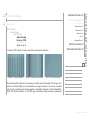
Pixel Tracking
Adjust Tracking
At entry=1756
---------Adjust using ^|v
Preferences .3
Advanced .4
Info .5
Changes Done .6
Serial commands C
“At entry=1756” shows the value used before entering this submenu.
figure B.1-1 (bad pixel tracking)
figure B.1-2 (almost ok pixel tracking)
Technical information D
U s i n g t h e A P - c o nve r t e r
B On Screen Display
figure B.1-3 (ok pixel tracking)
Pixel tracking (often referred to as frequency or width) controls the width of the image. Generally, an incorrect setting can be observed as an image too wide or too narrow, combined
with vertical, unstable bands and irregularities in the pattern displayed. Use the Nokia Monitors© Test Pattern software, or the 50% grey test pattern when performing adjustment
copyright Christie 2002.06
- 23 -
Keyboard functions A
On Screen Display B
Source Setup
procedures. Both can be downloaded from the Christie technical support pages at
www.christiedigital.com.
The AP-converter automatically adjusts the pixel tracking to match the incoming source, but
non-the-less it might be necessary to do final adjustments manually (unless the image signal
has already been stored). The AP-converter needs the image to have minimum one bright
pixel in both left and right border of the frame to do the adjustment. It also requires that the
guessed resolution is correct. This is the result in most cases, but if the auto setup doesn’t
provide you with a stable picture, a manual fine-tuning is needed.
If you are using analog VGA-cable, adjustments may have to be done in both the AP-converter
and the projector. Please refer to the user guide of your projector on how to adjust this. If
your AP-converter is connected to a projector using a DVI-cable this adjustment only has to
be done in the AP-converter (unless your projector overrides the DVI-signals).
Source Setup .1
Stereo Setup .2
Preferences .3
Advanced .4
Info .5
Changes Done .6
Serial commands C
Technical information D
U s i n g t h e A P - c o nve r t e r
B On Screen Display
Adjust the picture until you see no vertical bands. If you get rid of all the bands, but your
picture is still unstable, you will have to adjust the pixel phase as well.
Performing these adjustments requires carefulness and accuracy, but only has to be done
once per source. Make sure to store your settings after having achieved the desired result.
copyright Christie 2002.06
- 24 -
Keyboard functions A
On Screen Display B
Source Setup
Source Setup
Manual Setup
Pixel Phase
Adjust Phase
At entry=14
---------Adjust using ^|v
An image with an incorrect pixel phase can be seen as sideways instability or jitter/
swimming. Use this option to fine-tune the picture and get rid of any irregularities. Adjust
the pixel phase until you are satisfied with the result, and remember to store your settings.
The phase may need readjustment if you are using different cables to the AP-converter.
“At entry=14” shows the value used before entering this submenu.
Source Setup .1
Stereo Setup .2
Preferences .3
Advanced .4
Info .5
Changes Done .6
Serial commands C
Technical information D
U s i n g t h e A P - c o nve r t e r
B On Screen Display
Source Setup
Manual Setup
Brightness
Adjust Brightness
At entry=60
---------Adjust using ^|v
Brightness may be adjusted according to your personal taste, the image and the viewing
copyright Christie 2002.06
- 25 -
Keyboard functions A
On Screen Display B
Source Setup
Source Setup .1
Stereo Setup .2
conditions. Value 60 corresponds to normal setting with no gain. Higher value means higher
brightness.
“At entry=60” shows the value used before entering this submenu.
Preferences .3
Advanced .4
Info .5
Changes Done .6
Source Setup
Manual Setup
Contrast
Adjust Contrast
At entry=190
---------Adjust using ^|v
Contrast may be adjusted according to your personal taste, the image and the viewing conditions. Value 190 corresponds to normal setting with no gain. The higher the number gets,
the higher the contrast ratio becomes.
Serial commands C
Technical information D
U s i n g t h e A P - c o nve r t e r
B On Screen Display
“At entry=190” shows the value used before entering this submenu.
Source Setup
Manual Setup
DVI Position
----------
copyright Christie 2002.06
- 26 -
Keyboard functions A
On Screen Display B
Source Setup
Source Setup .1
Stereo Setup .2
Horizontal
Vertical
Adjustment of the actual DVI position is only affected when using DVI-cables/projectors.
Due to minor variations in graphic cards/drivers, the horizontal and vertical position may
need adjustment. Tune the vertical and horizontal position until you see the entire picture
within the projection area. Download the grid-pattern from the technical support page at
www.christiedigital.com, or use the Nokia Monitor Test program when adjusting DVI-position.
When using analog cables, adjusting this value changes the area where the edge-blending is
active. When using DVI the active edgeblend area will always be the area shown.
Source Setup
Manual Setup
DVI Position
Horizontal
Adjust Horizontal
At entry=364
---------Adjust using ^|v
Preferences .3
Advanced .4
Info .5
Changes Done .6
Serial commands C
Technical information D
U s i n g t h e A P - c o nve r t e r
B On Screen Display
“At entry=364” shows the value used before entering this submenu.
copyright Christie 2002.06
- 27 -
Keyboard functions A
On Screen Display B
Source Setup
Source Setup
Manual Setup
DVI Position
Vertical
Adjust Vertical
At entry=45
---------Adjust using ^|v
“At entry=45” shows the value used before entering this submenu.
Source Setup
Manual Setup
Picture Sync
---------Auto
SEP (H+V)
COMP
SOG
Source Setup .1
Stereo Setup .2
Preferences .3
Advanced .4
Info .5
Changes Done .6
Serial commands C
Technical information D
U s i n g t h e A P - c o nve r t e r
B On Screen Display
Default is Auto, and shouldn’t be changed unless you are experiencing trouble, or the APconverter doesn’t recognize the picture sync correctly. Choose the desired picture sync, and
press to activate.
copyright Christie 2002.06
- 28 -
Keyboard functions A
On Screen Display B
Source Setup
Source Setup
Manual Setup
Picture Sync
Auto
Source Setup .1
Stereo Setup .2
Preferences .3
Advanced .4
Info .5
Changes Done .6
Default is Auto, and shouldn’t be changed unless you are experiencing trouble.
Source Setup
Manual Setup
Picture Sync
SEP (H+V)
Use this option to manually force the AP-converter to sync on a separate Horizontal and
Vertical sync signal.
Serial commands C
Technical information D
U s i n g t h e A P - c o nve r t e r
B On Screen Display
Source Setup
Manual Setup
Picture Sync
COMP
Use this option to manually force the AP-converter to sync on a Composite sync signal.
copyright Christie 2002.06
- 29 -
Keyboard functions A
On Screen Display B
Source Setup
Source Setup
Manual Setup
Picture Sync
SOG
Source Setup .1
Stereo Setup .2
Preferences .3
Advanced .4
Info .5
Changes Done .6
Use this option to manually force the AP-converter to sync on a Sync-On-Green signal (SOG
are mostly used on Silicon Graphics (SGI) machines).
Serial commands C
Technical information D
Source Setup
Manual Setup
Sync Improvement
Use this option if you experience disturbing artifacts (line jitter) in the middle of the screen.
Refer to the serial command ISI for a closer explanation of this function.
U s i n g t h e A P - c o nve r t e r
B On Screen Display
Source Setup
Auto Setup
This option causes the AP-converter to analyse the incoming signal and perform an automatic adjustment.
WARNING: Forcing the AP-C
to sync on SOG without an
incoming SOG signal will render
your picture unstable, and may
cause it to disappear. In this
case you will have to reset the
AP-C to get the picture back.
copyright Christie 2002.06
- 30 -
Keyboard functions A
On Screen Display B
Source Setup
Source Setup
Revert Source
---------Press revert to the settings stored for this source
Source Setup .1
Stereo Setup .2
Preferences .3
Advanced .4
Info .5
Changes Done .6
Source Setup
Force Odd Res
---------Set X Resolution
Set Y Resolution
Run Force
Source Setup
Force Odd Res
Set X Resolution
---------1360
1280
1200
1152
1024
856
832
Serial commands C
Technical information D
U s i n g t h e A P - c o nve r t e r
B On Screen Display
copyright Christie 2002.06
- 31 -
Keyboard functions A
On Screen Display B
Source Setup
Source Setup .1
Stereo Setup .2
800
768
640
Other
Preferences .3
Advanced .4
Info .5
Changes Done .6
Source Setup
Force Odd Res
Set X Resolution
Other
At entry=800
---------Adjust using ^|v
“At entry=800” shows the value used before entering this submenu.
Serial commands C
Technical information D
U s i n g t h e A P - c o nve r t e r
B On Screen Display
Source Setup
Force Odd Res
Set Y Resolution
---------1024
960
900
864
copyright Christie 2002.06
- 32 -
Keyboard functions A
On Screen Display B
Source Setup
Source Setup .1
Stereo Setup .2
856
800
768
720
642
600
576
480
Other
Source Setup
Force Odd Res
Set Y Resolution
Other
At entry=600
---------Adjust using ^|v
Preferences .3
Advanced .4
Info .5
Changes Done .6
Serial commands C
Technical information D
U s i n g t h e A P - c o nve r t e r
B On Screen Display
“At entry=600” shows the value used before entering this submenu.
Source Setup
Force Odd Res
Run Force
copyright Christie 2002.06
- 33 -
Keyboard functions A
On Screen Display B
Source Setup
Source Setup .1
Stereo Setup .2
Choose this option if you want to run setup with the odd resolution selected. If you accidently
force a resolution that is not handled by the monitor or the projector, press > again to restore
default settings for this source.
Preferences .3
Advanced .4
Info .5
Changes Done .6
Source Setup
Store
Pressing will store the settings in a new (or same, if already stored) position, and the position number will be displayed. If the AP-converter displays “No changes done” the source is
already stored with the exact same settings. Press to return to navigation mode.
Serial commands C
Technical information D
U s i n g t h e A P - c o nve r t e r
B On Screen Display
Stereo Setup
When selecting the Stereo Setup menu from the Main Menu, the OSD will show the following:
Stereo Setup
---------Input
Output
Output Mode
copyright Christie 2002.06
- 34 -
Keyboard functions A
On Screen Display B
Stereo Setup
Stereo Setup
Input
---------Stereo Format
Stereo Sync
Eye Priority
Stereo Setup
Input
Stereo Format
---------Mono
Frame Sequential
Top/Bottom Halves
Line Interleaved
Source Setup .1
Stereo Setup .2
Preferences .3
Advanced .4
Info .5
Changes Done .6
Serial commands C
Technical information D
U s i n g t h e A P - c o nve r t e r
B On Screen Display
Stereo Setup
Input
Stereo Format
Mono
Choose this option to treat the incoming signal as a mono signal.
copyright Christie 2002.06
- 35 -
Keyboard functions A
On Screen Display B
Stereo Setup
Stereo Setup
Input
Stereo Format
Frame Sequential
Source Setup .1
Stereo Setup .2
Preferences .3
Advanced .4
Info .5
Changes Done .6
Use this option if your incoming stereosignal is frame sequential format. This is the default
setting.
Serial commands C
Technical information D
Stereo Setup
Input
Stereo Format
Top/Bottom Halves
Use this option if you are using an incoming stereosignal with top/bottom halves, also known
as above-below stereo.
U s i n g t h e A P - c o nve r t e r
B On Screen Display
Stereo Setup
Input
Stereo Format
Line Interleaved
Use this option if you are using an incoming stereosignal in line interleaved format.
copyright Christie 2002.06
- 36 -
Keyboard functions A
On Screen Display B
Stereo Setup
Stereo Setup
Input
Stereo Sync
---------Toggle Internal
Stereo Sync Source
Stereo Sync Pol
Source Setup .1
Stereo Setup .2
Preferences .3
Advanced .4
Info .5
Changes Done .6
Serial commands C
Technical information D
Stereo Setup
Input
Stereo Sync
Toggle Internal
Pressing
changes the polarity on the internal sync-generator. The toggle option is only
active when there is no external stereo sync present and the AP-converter runs on internal
stereo sync. It should be used when the left and right image is swapped, and the order needs
to be toggled.
U s i n g t h e A P - c o nve r t e r
B On Screen Display
Stereo Setup
Input
Stereo Sync
Stereo Sync Source
----------
copyright Christie 2002.06
- 37 -
Keyboard functions A
On Screen Display B
Source Setup .1
Stereo Setup
Stereo Setup .2
Auto
Cyvizync
Interlace
VGA pin 12
DIN connector
Internal
The AP-converter needs to know what type of stereo sync source the incoming signal is in
order to handle the signal correctly.
Stereo Setup
Input
Stereo Sync
Stereo Sync Source
Auto
Preferences .3
Advanced .4
Info .5
Changes Done .6
Serial commands C
Technical information D
U s i n g t h e A P - c o nve r t e r
B On Screen Display
Auto analyses the incoming signal and chooses the one it considers to be the correct one.
Use this mode if you are not sure which stereo sync you have.
copyright Christie 2002.06
- 38 -
Keyboard functions A
On Screen Display B
Stereo Setup
Stereo Setup
Input
Stereo Sync
Stereo Sync Source
Cyvizync
Use this mode if you have a stereo sync source that uses the length of the vertical sync for
stereo sync purposes.
Stereo Setup
Input
Stereo Sync
Stereo Sync Source
Interlace
Source Setup .1
Stereo Setup .2
Preferences .3
Advanced .4
Info .5
Changes Done .6
Serial commands C
Technical information D
U s i n g t h e A P - c o nve r t e r
B On Screen Display
Use this mode if you are using an interlaced format where odd fields represent the left eye
picture, and even fields represent the right eye picture. The order of these can be swapped
by changing the Stereo Sync Polarity.
copyright Christie 2002.06
- 39 -
Keyboard functions A
On Screen Display B
Stereo Setup
Stereo Setup
Input
Stereo Sync
Stereo Sync Source
VGA pin 12
Use this mode if you are using a stereo sync cable connected to a VGA to VGA + 3 pin miniDIN splitter, or any other cable using the signal from pin 12 on the VGA connector.
This is the default pin used by e.g. Elsa/nVidia and other consumer market equipment.
Stereo Setup
Input
Stereo Sync
Stereo Sync Source
DIN Connector
Source Setup .1
Stereo Setup .2
Preferences .3
Advanced .4
Info .5
Changes Done .6
Serial commands C
Technical information D
U s i n g t h e A P - c o nve r t e r
B On Screen Display
Use this mode if you are using a stereo sync cable connected to a separate stereo connector
(DIN) on your graphics card.
copyright Christie 2002.06
- 40 -
Keyboard functions A
On Screen Display B
Stereo Setup
Stereo Setup
Input
Stereo Sync
Stereo Sync Source
Internal
Use this option if you don’t have an incoming stereo sync signal, and want to use the built in
signal generator of the AP-converter. In this case you may use the toggle button when not
in the menu.
Stereo Setup
Input
Stereo Sync
Stereo Sync Pol
---------Normal
Inverted
Source Setup .1
Stereo Setup .2
Preferences .3
Advanced .4
Info .5
Changes Done .6
Serial commands C
Technical information D
U s i n g t h e A P - c o nve r t e r
B On Screen Display
Stereo Setup
Input
Stereo Sync
Stereo Sync Pol
Normal
copyright Christie 2002.06
- 41 -
Keyboard functions A
On Screen Display B
Stereo Setup
Source Setup .1
Stereo Setup .2
Normally the stereo sync polarity is left frame logically high, and right frame logically low for
DIN/VGA pin12. For Interlace odd fields is left frame, for above-below top picture is left
frame, and for line-interleaved first/odd lines are left frame.
Preferences .3
Advanced .4
Info .5
Changes Done .6
Stereo Setup
Input
Stereo Sync
Stereo Sync Pol
Inverted
Choose this mode if you need to reverse the stereo sync polarity. Changing the stereo sync
polarity will swap the left and right image.
Serial commands C
Technical information D
U s i n g t h e A P - c o nve r t e r
B On Screen Display
Stereo Setup
Input
Eye Priority
---------Left Then Right
Right Then Left
copyright Christie 2002.06
- 42 -
Keyboard functions A
On Screen Display B
Stereo Setup
Stereo Setup
Input
Eye Priority
Left Then Right
Source Setup .1
Stereo Setup .2
Preferences .3
Advanced .4
Info .5
Changes Done .6
Normally the Eye Priority is left eye first, and then right. Refer to technical pages for more
info on Eye Priority.
Serial commands C
Technical information D
Stereo Setup
Input
Eye Priority
Right Then Left
Use this mode if you need to change the eye priority to be right eye first, then left.
U s i n g t h e A P - c o nve r t e r
B On Screen Display
Stereo Setup
Output
---------Channel Swap
copyright Christie 2002.06
- 43 -
Keyboard functions A
On Screen Display B
Stereo Setup
Stereo Setup
Output
Channel Swap
---------Normal
Swapped
Stereo Setup
Output
Channel Swap
Normal
Normal configuration routes left and right channel to the correspondingly labelled outputs.
Source Setup .1
Stereo Setup .2
Preferences .3
Advanced .4
Info .5
Changes Done .6
Serial commands C
Technical information D
U s i n g t h e A P - c o nve r t e r
B On Screen Display
Stereo Setup
Output
Channel Swap
Swapped
This mode re-routes the signals causing the left channel to be displayed on the connector
labelled right channel, and visa versa.
copyright Christie 2002.06
- 44 -
Keyboard functions A
On Screen Display B
Stereo Setup
Stereo Setup
Output Mode
---------Vrate Sync Low
Vrate Sync High
Asynchronous
Stereo Setup
Output Mode
Vrate Sync Low
Use this option if you need to force the output vertical refresh rate to low.
Source Setup .1
Stereo Setup .2
Preferences .3
Advanced .4
Info .5
Changes Done .6
Serial commands C
Technical information D
U s i n g t h e A P - c o nve r t e r
B On Screen Display
Stereo Setup
Output Mode
Vrate Sync High
Use this option if you need to force the output vertical refresh rate to high.
copyright Christie 2002.06
- 45 -
Keyboard functions A
On Screen Display B
Stereo Setup
Stereo Setup
Output Mode
Asynchronous
Use this option if you need to force the output vertical refresh rate to stay within 60 to 70
Hz. This mode is not recommended for stereo viewing. Use this if the display device can not
handle the synchronous modes (the synchronous mode will either give output vertical refresh
rate half, equal or double the input vertical refresh rate)
Preferences
When selecting the Preferences menu from the Main Menu, the OSD will show the following:
Source Setup .1
Stereo Setup .2
Preferences .3
Advanced .4
Info .5
Changes Done .6
Serial commands C
Technical information D
U s i n g t h e A P - c o nve r t e r
B On Screen Display
Preferences
---------User Button
SOG Treshold
Serial Baudrate
Unit ID
Store Preferences
copyright Christie 2002.06
- 46 -
Keyboard functions A
On Screen Display B
Preferences
Preferences
User Button
---------No Action
TBH Stereo
LSS Stereo
Left Black
Stereo Sync Pol
Preferences
User Button
No Action
Selecting this option will at current have no action. Button is reserved for future functions.
Source Setup .1
Stereo Setup .2
Preferences .3
Advanced .4
Info .5
Changes Done .6
Serial commands C
Technical information D
U s i n g t h e A P - c o nve r t e r
B On Screen Display
Preferences
User Button
TBH Stereo
Choose this option if you want the user button to toggle between frame-sequential stereo
(FSS) and top/below halves stereo (TBH) on the input.
copyright Christie 2002.06
- 47 -
Keyboard functions A
On Screen Display B
Preferences
Preferences
User Button
LSS Stereo
Choose this option if you want the user button to toggle between frame-sequential stereo
(FSS) and line-sequential (LSS) input stereomode.
Preferences
User Button
Left Black
Select this option if you want the user button to toggle between normal and a black signal on
the left output channel.
Source Setup .1
Stereo Setup .2
Preferences .3
Advanced .4
Info .5
Changes Done .6
Serial commands C
Technical information D
U s i n g t h e A P - c o nve r t e r
B On Screen Display
Preferences
User Button
Stereo Sync Pol
Choose this option if you want the user button to toggle the stereo sync polarity.
copyright Christie 2002.06
- 48 -
Keyboard functions A
On Screen Display B
Preferences
Preferences
SOG Treshold
At entry=15
---------Adjust using ^|v
If you experience a missing or unstable picture when sync is set to SOG, you might have to
adjust the SOG Threshold. SOG Threshold will only be affected if picture sync is set to SOG.
Default level is 15.
Technical: Threshold voltage = (x+1) * 10 mV, where x is the number displayed on the APconverter.
“At entry=15” shows the value used before entering this submenu.
Source Setup .1
Stereo Setup .2
Preferences .3
Advanced .4
Info .5
Changes Done .6
Serial commands C
Technical information D
U s i n g t h e A P - c o nve r t e r
B On Screen Display
Preferences
Serial Baudrate
---------300
1200
2400
4800
9600
19200
copyright Christie 2002.06
- 49 -
Keyboard functions A
On Screen Display B
Source Setup .1
Preferences
Stereo Setup .2
38400
57600
115200
Pressing
Preferences .3
Advanced .4
Info .5
will make the AP-converter change the serial baudrate accordingly.
Changes Done .6
Serial commands C
Preferences
Unit ID
Adjust Unit ID
At entry=1
---------Adjust using ^|v
The Unit ID gives the ID of this unit when linked to other units. All linked units should have
different Unit ID’s for correct linking.
Technical information D
U s i n g t h e A P - c o nve r t e r
B On Screen Display
“At entry=1” shows the value used before entering this submenu.
Preferences
Store Preferences
---------Confirm using to save all data (User Button, SOG Treshold, Serial Baudrate, Unit ID).
copyright Christie 2002.06
- 50 -
Keyboard functions A
On Screen Display B
Advanced
Source Setup .1
Stereo Setup .2
When selecting the Advanced menu from the Main Menu, the OSD will show the following:
Advanced
---------Test Patterns
Reset
Factory Settings
Preferences .3
Advanced .4
Info .5
Changes Done .6
Serial commands C
Technical information D
Advanced
Test Patterns
---------Alignment Grid
Hor Moving Bars
Resolve
White
Black
Red
Green
Blue
Left/Right Ident
U s i n g t h e A P - c o nve r t e r
B On Screen Display
Use these test modes when you are aligning the projectors and adjusting the picture on the
projectors and the AP-converter.
copyright Christie 2002.06
- 51 -
Keyboard functions A
On Screen Display B
Source Setup .1
Advanced
Stereo Setup .2
Advanced
Test Patterns
Alignment Grid
Preferences .3
Advanced .4
Info .5
Pressing brings up a set of black and white alignment grids. Press
ous menu.
to return to the previ-
Serial commands C
Technical information D
Advanced
Test Patterns
Hor Moving Bars
Pressing
menu.
brings up a set of horizontal moving white bars. Press
Changes Done .6
to return to the previous
U s i n g t h e A P - c o nve r t e r
B On Screen Display
Advanced
Test Patterns
Resolve
Pressing brings up a set of black and white thin lines across the screen. Press
to the previous menu.
to return
copyright Christie 2002.06
- 52 -
Keyboard functions A
On Screen Display B
Source Setup .1
Advanced
Stereo Setup .2
Advanced
Test Patterns
White
Pressing
brings up a white screen. Press
Preferences .3
Advanced .4
Info .5
to return to the previous menu.
Changes Done .6
Serial commands C
Advanced
Test Patterns
Black
Pressing
brings up a black screen. Press
Technical information D
to return to the previous menu.
Advanced
Test Patterns
Red
Pressing
brings up a red screen. Press
U s i n g t h e A P - c o nve r t e r
B On Screen Display
to return to the previous menu.
copyright Christie 2002.06
- 53 -
Keyboard functions A
On Screen Display B
Source Setup .1
Advanced
Stereo Setup .2
Advanced
Test Patterns
Green
Pressing
brings up a green screen. Press
Preferences .3
Advanced .4
Info .5
to return to the previous menu.
Changes Done .6
Serial commands C
Advanced
Test Patterns
Blue
Pressing
brings up a blue screen. Press
Technical information D
to return to the previous menu.
Advanced
Test Patterns
Left/Right Ident
U s i n g t h e A P - c o nve r t e r
B On Screen Display
Pressing will cause the PA-converter to display the text “Right” on the right channel output,
and “Left” on the left channel output for easier identification of the different channels on the
output devices.
copyright Christie 2002.06
- 54 -
Keyboard functions A
On Screen Display B
Source Setup .1
Advanced
Stereo Setup .2
Advanced
Reset
Preferences .3
Advanced .4
This option will warm-reboot the AP-converter. All data not stored will be lost.
Info .5
Changes Done .6
Advanced
Factory Settings
---------Cancel
Restore
Advanced
Factory Settings
Cancel
Pressing
Serial commands C
Technical information D
U s i n g t h e A P - c o nve r t e r
B On Screen Display
will cancel the operation and return to the previous menu.
Advanced
Factory Settings
Restore
Pressing
will delete all user data and restore the AP-converter to factory settings.
copyright Christie 2002.06
- 55 -
Keyboard functions A
On Screen Display B
Source Setup .1
Info
Stereo Setup .2
When selecting the Info menu from the Main Menu, the OSD will show the following:
Preferences .3
Advanced .4
Info
---------Firmware
System Status
Source
Info .5
Changes Done .6
Serial commands C
Technical information D
Info
Firmware
Brings up a menu displaying:
Firmware version: 020625-160917
Serialnumber: AP0001
www.christiedigital.com
Info
U s i n g t h e A P - c o nve r t e r
B On Screen Display
System
Pressing
brings up a screen displaying
Signal status
= Showing
copyright Christie 2002.06
- 56 -
Keyboard functions A
On Screen Display B
Source Setup .1
Info
Stereo Setup .2
Active location
=
Search mode
Resolution
=
Pixelrate
=
Stereo mode in
=
Stereo sync present
Press
Info
49
= Auto
1280x1024p
191 MHz
FSS
= none
to return to previous menu.
Source
Pressing
brings up a screen displaying
Preferences .3
Advanced .4
Info .5
Changes Done .6
Serial commands C
Technical information D
U s i n g t h e A P - c o nve r t e r
B On Screen Display
Hsync is active low
Period
= 9.20 us
Frequency
= 108.70 KHz
Width
= 8.3 %
Vsync is active high
Period
= 9.98 ms
Frequency
= 100.18Hz
Lines
= 1085
Width
=3
Synctype
= SEP
copyright Christie 2002.06
- 57 -
Keyboard functions A
On Screen Display B
Source Setup .1
Info
Stereo Setup .2
The Active image synctype shows which picturesync the AP-converter currently works with.
The stereo sync present lists all the stereo syncs the AP-converter can detect. At least one
should be present when viewing stereo.
Preferences .3
Advanced .4
Info .5
Changes Done .6
The pixelrate shows the rate at which the AP-converter samples the incoming signal.
The resolution shows what the converter found the resolution to be. In case the converter
interprets the resolution wrong, you may force the converter to interpret it as a different
resolution by using the Force Odd Res menu under Source Setup.
Press
to return to previous menu.
Serial commands C
Technical information D
U s i n g t h e A P - c o nve r t e r
B On Screen Display
Changes Done
When exiting from the main menu after having done changes, the following menu appears:
The menu will not be displayed if you haven’t modified any settings.
Changes Done
---------Store
copyright Christie 2002.06
- 58 -
Keyboard functions A
On Screen Display B
Source Setup .1
Changes Done
Stereo Setup .2
Leave As Is
Restore
Preferences .3
Advanced .4
Info .5
Changes Done
Store
Pressing
Changes Done .6
Serial commands C
stores the new settings in the current position.
Note that pressing
will leave the settings as is. If you accidentially press
enter the menu, and exit once more. The store request will then re-appear.
Technical information D
, you may re-
Changes Done
Leave As Is
Pressing
U s i n g t h e A P - c o nve r t e r
B On Screen Display
exits the menu without saving.
Changes Done
Restore
Pressing restore will recall the settings from the stored position. If the source is not stored
the “restore” option will not be displayed.
copyright Christie 2002.06
- 59 -
Keyboard functions A
On Screen Display B
When leaving the OSD you might get the following warning if you are not using a stereo
sync cable.
Source Setup .1
Stereo Setup .2
Preferences .3
- - - - - Warning - - - - No stereo sync detected!
Outsignal is asynchronous!
If you are using a stereo sync cable and you still get this warning, make sure to check
your cabling, as the AP-converter is not recieveing the incoming sync-signal, or it might
not be active.
If the AP-Converter is having problems setting up the source, you might the following
message.
- - - - - Warning - - - - Autosetup failed
Advanced .4
Info .5
Changes Done .6
Serial commands C
Technical information D
U s i n g t h e A P - c o nve r t e r
B On Screen Display
In this case you should manually set up the source to get the best image.
copyright Christie 2002.06
- 60 -
Keyboard functions A
On Screen Display B
Summary
Serial commands C
The commands have been grouped by the following types with corresponding initial letters;
Initial letter
Summary .1
The help command .2
Type of command
Topics .3
I
Commands directly controlling the input
O
Commands controlling the outputs
SS
Commands controlling the stereo sync
Q
All query commands
Commands .4
Linking of units .5
Technical information D
Furthermore, the commands follow these general guidelines;
· All commands need to be ended with the ASCII code CR, (which is what happens when you
type enter on the keyboard). The LF (Hex 0A) will be ignored.
U s i n g t h e A P - c o nve r t e r
C Serial commands
· All accepted incoming characters will be echoed.
· Line feed from the AP-converter will be of type CR only.
· There is no need for a space between a command and it’s arguments.
· Multiple commands may be entered with the character “|” in between. For example the
command “AP>sst|ssp” typically will output “Stereo sync type (SST) = Auto” and “Stereo
sync polarity (SSP) = Normal”.
· All text after the characters “;” or “#” until CR will be ignored.
The commands are grouped
by type with corresponding initial letter(s).
The commands follow a set of
general guidelines.
You get the ACSII code CR
when you press enter on the
keyboard.
copyright Christie 2002.06
- 61 -
Keyboard functions A
On Screen Display B
The help command
Serial commands C
The help command is useful for getting more help on each command. You may use “help”
or “?” to get help.
To list all commands, use “? allcmds”.
To see all commands without explanation, use “? %allcmds”.
Also see Command: ?/Help in chapter C.4 (Serial commands/Commands) for further
information on using the help command.
Topics
Summary .1
The help command .2
Topics .3
Commands .4
Linking of units .5
Technical information D
U s i n g t h e A P - c o nve r t e r
C Serial commands
The AP-converter help commands also have a short explanation of some used topics.
Use the command “? alltopics” to list.
You may use “help” or “?” to
get help.
For an explanation of frequently used topics, use “? alltopics”
copyright Christie 2002.06
- 62 -
Keyboard functions A
On Screen Display B
Commands
Command:
Function:
%
[]
()
{}
Serial commands C
?/HELP [%][command/topic/wildcard/allcmds/alltopics]
Shows help on all or specific command.
shows short format
are optional arguments
are required arguments
is the default argument
No argument will show the current setting.
Command:
Function:
.[new arguments]
Repeats last command with new arguments.
This is very useful for manual search of correct values for commands like ISPL and IPHA.
Summary .1
The help command .2
Topics .3
Commands .4
Linking of units .5
Technical information D
U s i n g t h e A P - c o nve r t e r
C Serial commands
A typical output will show:
AP>ispl
Horizontal rate
(ISPL) = 1408 pixel/hsync
AP>.+
Horizontal rate
(ISPL) = 1410 pixel/hsync
copyright Christie 2002.06
- 63 -
Keyboard functions A
On Screen Display B
Commands
Command:
Function:
Serial commands C
,
Repeats last command with the same arguments.
Summary .1
The help command .2
Topics .3
Command:
Function:
QI [location]
Shows settings for parameters controlling the picture, ISPL, IPHA, IST, SMI,
IBR, ICO, DVIHPOS, DVIVPOS, NAMESRC for selected stored location.
If location is empty, the current settings will be shown.
A typical output will show:
AP>qi
Current settings (location 103)
Horizontal rate
(ISPL) = 1408 pixel/hsync
Hsync phase
(IPHA) = 0
Image synctype
(IST) = AUTO
Stereo mode in
(SMI) = Frame sequential (FSS)
Brightness
(IBR) = 60
Contrast
(ICO) = 190
DVI horizontal pos (DVIHPOS) = 276
DVI vertical pos (DVIVPOS) = 52
Name
(NAMESRC) = ‘VESA 1024x768@120Hz GTF TIMING’
Commands .4
Linking of units .5
Technical information D
U s i n g t h e A P - c o nve r t e r
C Serial commands
copyright Christie 2002.06
- 64 -
Keyboard functions A
On Screen Display B
Commands
Command:
Function:
Serial commands C
QS [location]
Show settings for global system parameters SST, SSP, SSEP, NAMESRC forselected stored location..
If location is empty, the current settings will be shown.
Typical outputs will show:
AP>qs
Stereo sync type (SST) = Auto (not present)
Stereo sync polarity (SSP) = 0, Left frame on long/even/high
Eye priority (SSEP) = Left first
Name (NAMESRC) = ‘VESA 1024x768@120Hz GTF TIMING’
Command:
Function:
QINFO [SO/SY]
Show system- and basic source-information.
Summary .1
The help command .2
Topics .3
Commands .4
Linking of units .5
Technical information D
U s i n g t h e A P - c o nve r t e r
C Serial commands
SO - source information
SY - system information
Typical outputs will show:
PA>qinfo so
Hsync is active high
Period = 18.42us
copyright Christie 2002.06
- 65 -
Keyboard functions A
On Screen Display B
Commands
Serial commands C
Frequency = 54.29KHz
Width = 8.3 %
Vsync is active high
Period = 19.99ms
Frequency = 50.04Hz
Lines = 1085
Width = 3
Synctype = SEP
PA>qinfo sy
Signal status = Showing
Active location = 103
Search mode = Auto
Resolution = 1280x1024p
Pixelrate = 95 MHz
Stereo mode in = SEP
Stereo syncs present = none
Command:
Function:
Summary .1
The help command .2
Topics .3
Commands .4
Linking of units .5
Technical information D
U s i n g t h e A P - c o nve r t e r
C Serial commands
ISPL (+/-/pixels pr line)
Reads/sets, increases or decreases the active samples per scanline including
sync and blank.
copyright Christie 2002.06
- 66 -
Keyboard functions A
On Screen Display B
Commands
Serial commands C
+/- will increase or decrease by 1 or 2 (depending on full or halfrate). Entering a number will
set the number entered.
A typical output will show:
AP>ispl
Pixcel tracking (ISPL) = 1408 pixel/hsync
Summary .1
The help command .2
Topics .3
Commands .4
Linking of units .5
Technical information D
Command:
Function:
IPHA (+/-/sampling phase)
Reads/sets the phase of the sampled pixel clock in relation to the hsync edge.
A typical output will show:
AP>ipha
Pixcel phase (IPHA) = 0
Command:
Function:
0
1
2
3
=
=
=
=
U s i n g t h e A P - c o nve r t e r
C Serial commands
IST (0-3/{AUTO}/SEP/COMP/SOG)
Reads/sets the synctype of the source signal.
AUTO
SEP (Separate)
COMP (Composite)
SOG (Sync on green)
copyright Christie 2002.06
- 67 -
Keyboard functions A
On Screen Display B
Commands
Serial commands C
A typical output will show:
AP>ist
Image synctype (IST) = AUTO
Summary .1
The help command .2
Topics .3
Commands .4
Command:
Function:
ISOGT (0-31)
Reads/sets the threshold level of SOG slicer.
A typical output will show:
AP>isogt
SOG threshold (ISOGT) = 15 (160mV)
Command:
Function:
IBR (0-127)
Reads/sets the offset/brightness. The default value is 60.
Linking of units .5
Technical information D
U s i n g t h e A P - c o nve r t e r
C Serial commands
Higher values give higher brightness.
The AP-converter clamps at the hsync period, and samples the black area of the incoming
signal. The displaying device connected to the outputs of the AP-converter may clamp elsewhere, and therefore the brightness level may not have the desired effect.
copyright Christie 2002.06
- 68 -
Keyboard functions A
On Screen Display B
Commands
Serial commands C
A typical output will show:
AP>ibr
Brightness (IBR) = 60
Summary .1
The help command .2
Topics .3
Commands .4
Command:
Function:
ICO (0-255)
Reads/sets the gain/contrast. The default value is 190.
A typical output will show:
AP>ico
Contrast
(ICO) = 190
Command:
Function:
DVIHPOS (0-..)
Reads/sets horizontal placement of DVI area.
Linking of units .5
Technical information D
U s i n g t h e A P - c o nve r t e r
C Serial commands
This command also affects the edge-blending area when using the VGA outputs.
A typical output will show:
AP>dvihpos
DVI horizontal pos (DVIHPOS) = 276
copyright Christie 2002.06
- 69 -
Keyboard functions A
On Screen Display B
Commands
Command:
Function:
Serial commands C
DVIVPOS (0-..)
Reads/sets vertical placement of DVI area.
This command also affects the edge-blending area when using the VGA outputs.
A typical output will show:
PA>dvivpos
DVI vertical pos
(DVIVPOS) = 52
Command:
Function:
ISI (0/1/disable/enable)
The “sync improvement” feature enables free running horizontal scan during
vertical blanking and is needed where your source has a synctype where horizontal sync is not present during vertical blanking.
Summary .1
The help command .2
Topics .3
Commands .4
Linking of units .5
Technical information D
U s i n g t h e A P - c o nve r t e r
C Serial commands
The sync coming out of the AP is half of the incoming, and therefore, on the output, this lack
of sync will give a very disturbing effect at the middle of the screen. Use “sync improvement”
to correct this problem. For non-technical users, leave this disabled if the picture looks ok.
The default setting for this is enabled for SOG and COMP synctypes, and disabled for SEP
synctypes.
copyright Christie 2002.06
- 70 -
Keyboard functions A
On Screen Display B
Commands
Command:
Function:
Serial commands C
IAUTO [!][hres[,vres]]
Tries to find settings automatically.
It does NOT save these settings into memory. If argument ! is given, the list of stored
sources will be checked first, and if found, it will recall the settings from there.
Command:
Function:
OBL [L/R/B/{N}]
Show black on Left/Right/Both/None of the outputs. Defaults to none.
Command:
Function:
OSP [(+/-,+/-)/I]
Set polarity of H and V output sync.
Summary .1
The help command .2
Topics .3
Commands .4
Linking of units .5
Technical information D
U s i n g t h e A P - c o nve r t e r
C Serial commands
Default is the same as the input syncs. Parameter I copies input sync polarity.
Command:
Function:
OSM (0-2/SYNCLO/SYNCHI/ASYNC)
Sets the output scan mode.
At full rate the out signal will have the same vertical refresh rate as the output, with every
frame input twice.
copyright Christie 2002.06
- 71 -
Keyboard functions A
On Screen Display B
Commands
Serial commands C
0=Synclo:
The output rate will be within 43-85Hz. The unit will try to half the framerate to get the output
within this range.
1=Synchi:
The output rate will be within 90-140Hz. The unit will try to double the framerate to get the
output within this range.
2=Async:
The output rate will be within 60-75Hz regardless of input rate. Frame tearing will occur
in this mode. This mode should only be used when no other mode will make reasonable
output.
Command:
Function:
OTST [testnumber]
Shows specified testsignal.
Summary .1
The help command .2
Topics .3
Commands .4
Linking of units .5
Technical information D
U s i n g t h e A P - c o nve r t e r
C Serial commands
If the parameter is omitted, the testsignal is switched off.
A typical output will show:
->TESTNUMBER<0/no number/default=off
1=Grid for alignment. When aligned, it will become white.
2=Horizontally moving vertical bar. For v-sync test.
copyright Christie 2002.06
- 72 -
Keyboard functions A
On Screen Display B
Commands
Serial commands C
3=Black/White vertical lines
4=White
5=Black
6=Red
7=Green
8=Blue
9=Left/Right text
Command:
Function:
OSW (0/1/ON/OFF/TOG)
Swaps left and right output channels.
Command:
Function:
UNDO
Reloads all parameters from stored settings (if exists).
Command:
Function:
RS
Soft-resets the AP-converter.
Command:
Function:
SEARCH [{ON}/OFF]
Enables or disables automatic search for new sources.
Summary .1
The help command .2
Topics .3
Commands .4
Linking of units .5
Technical information D
U s i n g t h e A P - c o nve r t e r
C Serial commands
copyright Christie 2002.06
- 73 -
Keyboard functions A
On Screen Display B
Commands
Serial commands C
When no parameter is given, the search is enabled. When on, the unit will, as soon as it
sees a different source, look for it in the table of known sources. If it is found, the settings will
be loaded from the list. If not found the IAUTO command will be run. When off, no changes
will be made to any parameters when a new source is found. This is for debugging only.
A typical output will show:
AP>search off
Manual mode.
Forced location 103.
Command:
Function:
SMI[0-3/MON/FSS/TBH/LSS]
Set the input stereomode.
0/MON = Mono
1/FSS = Frame sequential
2/TBH = Top/bottom halves
3/LSS = Line interleaved/Line sequential
Command:
Function:
Summary .1
The help command .2
Topics .3
Commands .4
Linking of units .5
Technical information D
U s i n g t h e A P - c o nve r t e r
C Serial commands
SST (0-4/AUTO/INT/DIN/VGA/CYV/ILA)
Selects incoming stereo sync type.
0 = Auto. Search order:SSCYVIZ,SSILA,SSEXTV,SSEXTD,SSINT.
copyright Christie 2002.06
- 74 -
Keyboard functions A
On Screen Display B
Commands
1
2
3
4
5
=
=
=
=
=
Serial commands C
Cyvizync (SSCYVIZ). Length of Vsync (short=right, long=left).
Interlace fields (SSILA). odd/even fields becomes left/right.
External VGA connector (SSEXTV).
External DIN connector (SSEXTD).
Internal/toggle-able free running sync (SSINT).
When a sync is selected, but not present, the internal will be used.
You may map these syncs correctly using SSP and SSEP.
Command:
Function:
SSEP (0-1/LF/RF)
Selects eye priority. Used to tell which image appears first (on the in signal) of
a pair of images.
0 = left+following right belongs together (Normal on FSS).
1 = right+following left.
Summary .1
The help command .2
Topics .3
Commands .4
Linking of units .5
Technical information D
U s i n g t h e A P - c o nve r t e r
C Serial commands
This must be set correctly in order to reduce eyestrain on moving stereo-images. See
Part I (Setting up the AP-converter), chapter C.1 (Eye strain/Checking left and right
image).
A typical output will show:
AP>ssep
Eye priority (SSEP) = Left first
copyright Christie 2002.06
- 75 -
Keyboard functions A
On Screen Display B
Commands
Command:
Function:
Serial commands C
SSP [0-1/NORM/INV/TOG]
Toggles or sets the polarity of outgoing stereo sync signal
0/NORM is Left frame on high(DIN)/long(SSCYVIZ)
1/INV is Right frame on high(DIN)/long(SSCYVIZ)
A typical output will show:
AP>ssp
Stereo sync polarity (SSP) = Normal
Command:
Function:
TG
Toggles internal stereo sync polarity. Use SSP to change the external sync
polarity.
Command:
Function:
CLEANUPSRC
Clean up the storage area.
Summary .1
The help command .2
Topics .3
Commands .4
Linking of units .5
Technical information D
U s i n g t h e A P - c o nve r t e r
C Serial commands
Because of the way things are stored, a cleanup is needed if you have done a lot of changes
and storing of sources.
If you use the STORE function and a cleanup is needed, the AP-converter will tell you. Use the
parameter F only if you want to manually force the converter to perform a cleanup.
copyright Christie 2002.06
- 76 -
Keyboard functions A
On Screen Display B
Commands
Command:
Function:
Serial commands C
NAMESRC (name)
Sets the name of the current source.
This name will be stored when the store command is used.
A typical output will show:
AP>namesrc
Name (NAMESRC) = ‘VESA 1024x768@120Hz GTF TIMING’
Command:
Function:
STORE [SYSTEM/(location)]
Stores the source settings.
Stores the settings at the active location (if already stored), at the first free location, or at
the location specified (if not stored). You will get an error message if you try to store a source
wich already exists into a different location. Two identical sources can not be stored twice.
Summary .1
The help command .2
Topics .3
Commands .4
Linking of units .5
Technical information D
U s i n g t h e A P - c o nve r t e r
C Serial commands
See Part III (Appendixes), chapter D.6 (Technical Information/Handling of sources),
for more information on this subject.
If parameter is omitted, the active location (if any) will be overwritten.
If no location is active, the next free location is selected and activated.
copyright Christie 2002.06
- 77 -
Keyboard functions A
On Screen Display B
Commands
Serial commands C
If the parameter is ‘SYSTEM’ then the current system settings will be stored and used at next
power up.
Summary .1
The help command .2
Topics .3
Command:
Function:
SYSSTORE
Stores global settings like serial baudrate, unit id and user button mapping.
Commands .4
Linking of units .5
Technical information D
Command:
Function:
DELSRC (location)
Deletes the source settings at the specified location.
Command:
Function:
LISTSRC @[loc[,toloc]]
Lists the stored sources.
U s i n g t h e A P - c o nve r t e r
C Serial commands
If no argument is given, the active location is listed. If only loc is given, only this is listed. If
also the toloc is given, all locations between loc and toloc are listed. Use @ to list as detailed
mode.
The list shows all the parameters used to recognize the source, together with its settings
stored at the position.
A typical output will show:
AP>listsrc
copyright Christie 2002.06
- 78 -
Keyboard functions A
On Screen Display B
Commands
Serial commands C
Listing active location (103):
103 >1068 3 1868 331 1 1 1 0: ‘TEST’,
1640,24,15,0,0,0,0,0,0,1,1,190,60,278,41,1280,1024;
This is the function of the numbers;
103
>
1068
3
1868
331
1
1
1
0
:
‘TEST’
1640
24
15
0
0
=
=
=
=
=
=
=
=
=
=
=
=
=
=
=
=
=
The location for this source
Separator
Number of lines between each vertical sync
Duration of vertical sync (number of lines)
Duration (in 100Mhz cycles) between the horizontal syncs
Duration (in 100Mhz cycles) of the horizontal sync width
Positive (active high) vertical sync polarity (0=neg, 1=pos, 3=don’t care)
Positive (active high) horizontal sync polarity (0=neg, 1=pos, 3=don’t care)
SEP sync type (0=any, 1=separate, 2=composite, 3=SOG)
Progressive scan type (0=progressive, 1=interlaced)
Separator between the identity parameters and the settings
Name of the stored source (NAMESRC)
Pixel tracking value (ISPL)
Pixel phase (IPHA)
SOG threshold (160mV) (ISOGT)
Image synctype to be used (IST) (0=auto, 1=separate, 2=composite, 3=SOG)
Input stereomode (SMI) (0=MON (Mono), 1=FSS (Frame Sequential),
2=TBH (Top Below Halves), 3=LSS (Line Interleaved/Line sequential)
Summary .1
The help command .2
Topics .3
Commands .4
Linking of units .5
Technical information D
U s i n g t h e A P - c o nve r t e r
C Serial commands
copyright Christie 2002.06
- 79 -
Keyboard functions A
On Screen Display B
Commands
0
0
0
1
1
190
60
278
41
1280
1024
Command:
Function:
Serial commands C
= Stereo sync type used (SST) (0=Auto, 1=Cyvizync (SSCYVIZ), 2=Interlace
fields, 3=External VGA, 4=External DIN, 5=Internal)
= Output swap (OSW) (0=off/normal, 1=on/swapped)
= Output sync mode (OSM) (0=vrate synchronous low, 1=vrate synchronous
high, 2=asynchronous tear)
= Output horizontal sync polarity (0=active low, or negative, 1=active high or
positive)
= Output vertical sync polarity (0=active low, or negative, 1=active high or
positive)
= Contrast (ICO)
= Brightness (IBR)
= DVI horizontal position (DVIHPOS)
= DVI vertical position (DVIVPOS)
= Horizontal resolution (1280 pixels)
= Vertical resolution (1024 pixels)
Summary .1
The help command .2
Topics .3
Commands .4
Linking of units .5
Technical information D
U s i n g t h e A P - c o nve r t e r
C Serial commands
KEY (MENU/MODE/RBLACK/TGL/ENTER/BACK/UP/DOWN/LEFT/
RIGHT/POWERON/POWEROFF)
Simulates a keypress.
The KEY command brings up the OSD display, and simulates pressing the buttons on the the
keypad.
copyright Christie 2002.06
- 80 -
Keyboard functions A
On Screen Display B
Commands
Command:
Function:
Serial commands C
RESTOREFACTORYSETTINGS
Restores the factory settings. Will NOT ask for confirmation.
A typical output will show:
AP>restorefactorysettings
Restoring factorysettings.
Erasing old data..ok.
Programming sources.. Ok - Resetting.
Christie Digital Systems, Inc
Firmware version:020626-130349
Serial number:AP0001
www.christiedigital.com
Command:
Function:
Summary .1
The help command .2
Topics .3
Commands .4
Linking of units .5
Technical information D
U s i n g t h e A P - c o nve r t e r
C Serial commands
COMSET (@baudrate/preset)
This command sets the serialport baudrate.
Use @ to set a non-standard baudrate. The device will report the real baudrate it sets before
switcing to the new rate.
Presets:
0 = 300 baud
1 = 1200 baud
copyright Christie 2002.06
- 81 -
Keyboard functions A
On Screen Display B
Commands
2
3
4
5
6
7
8
=
=
=
=
=
=
=
Serial commands C
2400 baud
4800 baud
9600 baud
19200 baud
38400 baud
57600 baud
115200 baud
A typical output will show:
AP>comset @57600
Actual rate set to 57600 bps.
Command:
Function:
FRZ 0/1/ON/OFF/TOG
Sets/resets freeze of a picture pair.
Summary .1
The help command .2
Topics .3
Commands .4
Linking of units .5
Technical information D
U s i n g t h e A P - c o nve r t e r
C Serial commands
The freeze is synchronized at the end of a picture pair, so you will always see 2 complete
pictures as they appear from the source.
A typical output will show:
AP>frz tog
Freeze is now on.
copyright Christie 2002.06
- 82 -
Keyboard functions A
On Screen Display B
Commands
Command:
Function:
Serial commands C
USERB (0-4/NONE/TBH/LSS/RBL/SSP)
Set the function of the userbutton on the keyboard.
0/NONE = no function
1/TBH = Toggle between SEP and TBH stereomode
2/LSS = Toggle between SEP and LSS stereomode
3/LBL = Toggle left output black
4/SSP = Toggle stereo sync polarity
Command:
Function:
SV
Shows software version and serial number.
A typical output will show:
Firmware version:020604-165555
Serialnumber:PA0001
www.christiedigital.com
Command:
Function:
Summary .1
The help command .2
Topics .3
Commands .4
Linking of units .5
Technical information D
U s i n g t h e A P - c o nve r t e r
C Serial commands
UNITID id[,SNR]
Set the identity-number of the unit having the specified serialnumber.
SNR may only be omitted if hooked to the unit via the RS232. The format of snr is the same
copyright Christie 2002.06
- 83 -
Keyboard functions A
On Screen Display B
Commands
Serial commands C
format as found at the label of the box, or from the SV command. If you enter the wrong
serial number and get no response from the AP-converter, type atn0 and press enter to
bring back the prompt (characters might not be displayed whilst typing).
Summary .1
The help command .2
Topics .3
Commands .4
Command
Function:
ATN id
Sets the attention of the unit having the selected id.
When linking, it sets the attention of the device having UNITID = id. All commands after this
will go to this unit. This command is silent.
Command:
Function:
QATN
Query the attention status, shows id and master/slave of selected unit.
Linking of units .5
Technical information D
U s i n g t h e A P - c o nve r t e r
C Serial commands
Used for debugging to view the device’ attention status.
Command:
Function:
MASTER
Set unit to master
When linking 2 units or more, one device needs to be the master. Using this command
enables the master. This command only works on the RS232 port, not on the linkport. The
master status will be stored when using the SYSSTORE command. This command is silent.
copyright Christie 2002.06
- 84 -
Keyboard functions A
On Screen Display B
Commands
Command:
Function:
Serial commands C
ECORR
Load edge correction data
See separate documentation on how to use this command.
Command:
Function:
EDGUSE loc
Load edge+black correction data from stored memory from position x
See separate documentation on how to use this command.
Command:
Function:
EDGSTORE loc/ERASE/DEFAULTS/CLEANUP
Save edgeblend settings at selected loc.
Summary .1
The help command .2
Topics .3
Commands .4
Linking of units .5
Technical information D
U s i n g t h e A P - c o nve r t e r
C Serial commands
See separate documentation on how to use this command.
Command:
Function:
EDGDEL loc
Delete edgeblend settings at selected loc.
See separate documentation on how to use this command.
copyright Christie 2002.06
- 85 -
Keyboard functions A
On Screen Display B
Commands
Command:
Function:
Serial commands C
BCORR
Load black correction data
See separate documentation on how to use this command.
Summary .1
The help command .2
Topics .3
Commands .4
Linking of units .5
Technical information D
Linking of units
Several AP-converter units may be linked together and controlled from a single RS232 port.
This is particularly useful when you have large setups, e.g for edgeblending.
Use the RS232 serial cable that comes with the AP-converter to connect to serial port 1 on
the first unit. Then use a regular UTP network cable (RJ45) from port 2 on the first unit and
connect this to port 1 on the next unit, and repeat this for every unit you want to connect.
U s i n g t h e A P - c o nve r t e r
C Serial commands
To enable linking, there must be a master unit, and all units must have their own unique unitid
code. This must be set on the osd menu (global settings) or if you know the serialnumber of
the unit, you may set it using the serial terminal and the unitid command.
First, after powerup, make sure the unit hooked to the RS232 is master by typing “master”.
Note that this command is silent, and will not promt or answer. Press enter again to get a
prompt.
copyright Christie 2002.06
- 86 -
Keyboard functions A
On Screen Display B
Linking of units
You may set the unitid’s by using the “unitid id,snr” where the snr is the serialnumber of the
unit. Press enter to get prompt. If no prompt is shown, there is a problem communicating
with the unit. If you loose the prompt completely, type “atn0” to get back to the master.
The master mode may be stored for next powerup by using the command “sysstore”.
To talk to a specific unit, use “atn id” where id is the unit with unitid=id. If everything is
working, pressing enter should give you a prompt with the unitid of the answering unit (for
example, “atn 5” should say “5:AP>”) All commands sent will now go to this unit only.
Serial commands C
Summary .1
The help command .2
Topics .3
Commands .4
Linking of units .5
Technical information D
U s i n g t h e A P - c o nve r t e r
C Serial commands
copyright Christie 2002.06
- 87 -
Keyboard functions A
On Screen Display B
Different types of picture signal
Serial commands C
There are 3 main sync types used in computer video signals, (separate sync, composite sync,
and sync on green) which are all supported by the AP-converter.
Technical information D
Different types of picture signal .1
Different types of stereo sync .2
Different types of stereo sync .3
connectors -----
Different types of stereo sync
The AP-converter needs to know which part of the signal belongs to the left and right
image.
There are 4 main methods of obtaining correct stereo sync for the AP-converter:
VESA 3pin mini DSUB connector (SSEXTD)
Separate stereo sync through a standard VESA 3pin mini DSUB connector.
Left/right sequence in frame .4
sequential stereo
Handling of sources .5
U s i n g t h e A P - c o nve r t e r
D Technical information
See 3pin mini din, chapter D.3 (Different types of stereo sync connectors) .
VGA pin12 plug (SSEXTV)
Cheaper graphics cards use VGA pin12 plug (which originally is used for VESA DDC communication).
See VGA pin 12, chapter D.3 (Different types of stereo sync connectors).
The AP-converter support all
main sync types.
There are 3 main methods of
stereo sync for the AP-converter.
copyright Christie 2002.06
- 88 -
Keyboard functions A
On Screen Display B
Different types of stereo sync
CyvizSync (SSCYVIZ)
This sync uses the length of the vertical sync for the stereo sync. It is defined by Cyviz at
http://www.cyviz.com.
Serial commands C
Technical information D
Different types of picture signal .1
Different types of stereo sync .2
Interlace (SSILA)
The phase between the vsync and hsync.
Different types of stereo sync .3
connectors ----Left/right sequence in frame .4
sequential stereo
Handling of sources .5
Different types of stereo sync connectors
3pin mini din
This plug is defined by StereoGraphics at http://www.stereographics.com
U s i n g t h e A P - c o nve r t e r
D Technical information
7pin mini din (SUN)
To use this you need a 3pin mini-din adapter.
8pin mini din (SGI)
To use this you need a 3pin mini-din adapter.
9pin DSUB (SGI)
To use this you need a 3pin mini-din adapter.
copyright Christie 2002.06
- 89 -
Keyboard functions A
On Screen Display B
Different types of stereo sync connectors
VGA pin 12
Some graphics cards use pin 12 of the VGA connector (which originally is used for transferring DDC data during monitor identification) as stereo sync.
At the time of writing this, most ELSA cards using the revelator drivers use this type of
stereo sync. The AP-converter may use this if selected using “SST” command.
Serial commands C
Technical information D
Different types of picture signal .1
Different types of stereo sync .2
Different types of stereo sync .3
connectors ----Left/right sequence in frame .4
sequential stereo
Handling of sources .5
Left/right sequence in frame sequential stereo
The left and right frame coming from a frame-sequential source needs to be output correctly
to get an optimal viewing condition.
U s i n g t h e A P - c o nve r t e r
D Technical information
When you have moving objects on the screen, it is especially important that the left and
right frames are output correctly.
Usually the frames come out in pairs, where the left and the next right frame were rendered
at the same point of time. These need to be output at the same time. To make sure this is
happening, you need to know how the computer does this. You may change this sequence
by using the SSEP and SSP commands on the serial interface.
copyright Christie 2002.06
- 90 -
Keyboard functions A
On Screen Display B
Left/right sequence in frame sequential stereo
It is recommended that you use one of the stereo sync methods described in chapter
D.2 (Different types of stereo sync).
To illustrate this, some drawings follow below. The difference is clearly visible when objects
on the screen are moving, even if the frames are changing slowly due to complex objects.
Correct stereo sync at half rate:
Serial commands C
Technical information D
Different types of picture signal .1
Different types of stereo sync .2
Different types of stereo sync .3
connectors ----Left/right sequence in frame .4
sequential stereo
Handling of sources .5
U s i n g t h e A P - c o nve r t e r
D Technical information
Note: There is 1 frameset delay.
copyright Christie 2002.06
- 91 -
Keyboard functions A
On Screen Display B
Left/right sequence in frame sequential stereo
Wrong stereo sync polarity at half rate:
Serial commands C
Technical information D
Different types of picture signal .1
Different types of stereo sync .2
Different types of stereo sync .3
connectors ----Left/right sequence in frame .4
sequential stereo
Handling of sources .5
There will be a 1 frame delay between left and right eye if stereo sync is inverted and
outputs are swapped.
U s i n g t h e A P - c o nve r t e r
D Technical information
If the source sends a stereo sync signal with settings “right frame high”, the AP-converter detects this as “left frame high” because of it’s default settings. To change this,
change the stereo sync polarity in the menu, or by using the command ssp.
If you have this problem you might think you have the correct setting after swapping left
and right channels, but you will actually get a delay on the left channel causing eye-strain,
when things on the screen are moving. Therefore, do the setup procedure exactly as
described in chapter B (Setup procedure) of Part I (Setting up the AP-converter).
copyright Christie 2002.06
- 92 -
Keyboard functions A
On Screen Display B
Left/right sequence in frame sequential stereo
Correct stereo sync at equal rate:
Serial commands C
Technical information D
Different types of picture signal .1
Different types of stereo sync .2
Different types of stereo sync .3
connectors ----Left/right sequence in frame .4
sequential stereo
Handling of sources .5
U s i n g t h e A P - c o nve r t e r
D Technical information
Handling of sources
The AP-converter continously looks for a signal on the input. When a stable input is found, it
measures these parameters:
·
·
·
·
horizontal and vertical sync lengths
horizontal and vertical scan-frequencies
horizontal and vertical sync polarity (for separate sync only)
the type of sync (separate sync, composite sync or sync on green)
Similar effects will occur in all
output formats.
copyright Christie 2002.06
- 93 -
Keyboard functions A
On Screen Display B
Handling of sources
These values are compared with a list of pre-programmed sources. If the parameters match,
all settings (also stored in the table) for this match will be loaded and activated.
If the souce is not found in the table of pre-programmed sources, the AP-converter will guess
the resolution based on the picture contents and the number of vertical lines in the picture.
It will then try to auto-setup all necessary settings on its own. Sometimes the AP-converter
will not be able to set the best settings (especially if the desktop background is dark, or if it’s
an odd resolution), and may need manual help from the user. See Pixel tracking in Part II
(Using the AP-converter), chapter B.1 (On Screen Display/Source setup).
The AP-converter will NOT store new source settings automatically. When you are pleased
with the settings, you should store the source in the list of pre-programmed sources (the
OSD menu will ask if you want to store when leaving the menu). This makes it easy for the
AP-converter to load the correct settings the next time it detects this source.
Serial commands C
Technical information D
Different types of picture signal .1
Different types of stereo sync .2
Different types of stereo sync .3
connectors ----Left/right sequence in frame .4
sequential stereo
Handling of sources .5
U s i n g t h e A P - c o nve r t e r
D Technical information
copyright Christie 2002.06
- 94 -
Requirements A
Keyboard functions A
Serial interface A
PC and graphics card
Projectors
Screen
Polarizing filters
Viewing glasses
.1
.2
.3
.4
.5
Setup procedure B
Connecting projectors
Connecting the PC
Aligning the projector
Setting up linear polarizing filters
Enabling the stereo software
Connect the stereo sync cable
.1
.2
.3
.4
.5
.6
Eyestrain C
Checking left and right image
Software parameters
Wrong setup of polarizing filters
Color- or brightness-differences
in projectors
Moving objects
.1
.2
.3
.4
----.5
Remote controlling D
LED indicators
Standby button
Toggle button
Right black button
User button
Menu button
Cursor buttons
.1
.2
.3
.4
.5
.6
.7
On Screen Display B
Source Setup
Stereo Setup
Preferences
Advanced
Info
Changes Done
.1
.2
.3
.4
.5
.6
Serial commands C
Summary
The help command
Topics
Commands
Linking of units
.1
.2
.3
.4
.5
Technical information D
Different types of picture signal
Different types of stereo syncs
Different types of stereo sync
connectors
Left/right sequence in frame
sequential stereo
Handling of sources
.1
.2
.3
----.4
.5
more information on previous page
more information on next page
more information on both previous and next page
highly important information
note
more information available elsewhere
Connection .1
Setting up HyperTerminal .2
Setting up other systems .3
Firmware upgrade B
Using Windows .1
Using non-Windows terminal .2
Connectors C
VGA input
Monitor redraw
Power input
Stereo sync input
Stereo sync output
Serial plug 1
Serial plug 2
DVI-D left and right output
VGA left and right output
Serial RS-232 cable
.1
.2
.3
.4
.5
.6
.7
.8
.9
.10
Technical specification D
Functions
Dimensions
Compatibility
Inputs
Outputs
Supplied material
.1
.2
.3
.4
.5
.6
Appendi xes
Part III
Usi ng the AP-convert er
Part II
Setti ng up the AP-co nver te r
Part I
Serial interface A
Connection .1
The AP-converter is prepared for serial (RS-232) controlling and firmware upgrading. To
use this serial interface you need a terminal-software like the HyperTerminal found in most
Windows installations and a serial cable connection.
In Windows OS, the HyperTerminal can normally be found in the start menu/programs/
accessories/communications.
Setting up HyperTerminal .2
Setting up other systems .3
Firmware upgrade B
Connectors C
Technical specification D
A p p e n d i xe s
A Serial interface
Connection
Connect the AP-converter serial cable between one of the RS-232 ports (COM1, 2...) on the
computer and the serial port #1 (IOIO1) on the AP-converter.
If your computer have a 25pin serial port you need an adapter from 25pin male to 9pin
female.
See chapter C.8 (Serial RS-232 cable) for pin configuration on AP-converter serial
cable.
Setting up HyperTerminal
To set-up serial control with HyperTerminal, do the following:
· Start the HyperTerminal program.
· A window will appear asking for a name on your new connection.
copyright Christie 2002.06
- 96 -
Serial interface A
Connection .1
Setting up HyperTerminal .2
Setting up HyperTerminal
Setting up other systems .3
On NT, the computer may ask for modem/dial properties
first. If so, just enter some random nombers until you get to
this window.
·
Type“AP-converter”andclickOK.
Firmware upgrade B
Connectors C
Technical specification D
A p p e n d i xe s
A Serial interface
·
Select Direct to ComX where X is the COM port you have
plugged the AP-converter into. (Normally this is COM1 or
COM2).
·
CcilO
kK.
copyright Christie 2002.06
- 97 -
Serial interface A
Connection .1
Setting up HyperTerminal .2
Setting up HyperTerminal
Setting up other systems .3
· Set the parameters as follows:
Bitspersecondto19200/38400/57600/115200
Firmware upgrade B
Databitsto“8”
Connectors C
Parityto“None”
Technical specification D
A p p e n d i xe s
A Serial interface
Stopbitsto“1”
Flowcontrolto“None”
·
CcilO
kK.
·
SelectPropertiesintheFilemenu.
·
In the menu window that appears, select ASCII Set up...
under Settings.
copyright Christie 2002.06
- 98 -
Serial interface A
Connection .1
Setting up HyperTerminal .2
Setting up HyperTerminal
Setting up other systems .3
·
Check all boxes, except the Echo typed charters locally
and Force incoming data to 7-bit ASCII.
Firmware upgrade B
Do not check Echo typed charters locally and Force
incoming data to 7-bit ASCII.
Technical specification D
·
Set the Line delay to “0” and the Character delay to “0”.
·
CcilO
kK.
Connectors C
A p p e n d i xe s
A Serial interface
· Ensure that both serial and power cable is properly connected to the AP-converter.
· Press enter in the terminal window.
The AP-converter should respond with “AP>”.
· Use the command “? ALLCMDS” and press enter to get a complete list of all the available
commands.
copyright Christie 2002.06
- 99 -
Serial interface A
Connection .1
Setting up other systems
The AP-converter communicates through a normal RS-232 using the following parameters:
· baudrate (selectable)
· parity: none
· 8 bits
Setting up HyperTerminal .2
Setting up other systems .3
Firmware upgrade B
Connectors C
Technical specification D
A p p e n d i xe s
A Serial interface
· 1 startbit
· no handshake
· no echo
· Tx linefeed: CR only
· Rx linefeed: CR only
Your serial port must be set up according to the above listed parameters.
copyright Christie 2002.06
- 100 -
Serial interface A
Firmware upgrade B
Using windows
Using Windows .1
The internal control software (firmware) in the AP-converter can be upgraded through the
serial communication.
New firmware files (*.bin) can be downloaded from the technical support pages at
www.christiedigital.com
Using non-Windows terminal .2
Connectors C
Technical specification D
A p p e n d i xe s
B Firmware upgrade
When you have downloaded and are ready to upgrade, please do the following:
· Start the “AP-converter” session in HyperTerminal
· Press enter in the terminal window to confirm the connection. The AP-converter should
respond with “AP>”.
·
UnplugpowertoAP-converter.
·
Pressandholdthebuttonthatcorresponds
to your transfer speed. This setting has
to match the setting in your terminal program. (See figure B.1-1 on the right). (For older units without the monitor redraw, only
19200 is possible. Press and hold the power button to enable this mode).
· Reconnect the power plug whilst still pressing the button down.
· Release the button when HyperTerminal prompt with BOOT>. If your output is garbled,
the transfer rate of the AP-converter and the terminal program doesn’t match.
· Write the command “ERASEFIRM” and press enter, confirm with “ERASEFIRM YES” and
press enter again.
In Windows OS, the HyperTerminal can normally be found in
the start menu/programs/
accessories/communications.
To find the latest available firmware upgrades please visit our
technical support pages at
www.christiedigital.com
copyright Christie 2002.06
- 101 -
Serial interface A
Firmware upgrade B
Using windows
Using Windows .1
Using non-Windows terminal .2
· Wait until the firmware is erased and then write the command “LOADFIRM” and press
enter. You now have to start sending the file within 40 seconds, or the AP-converter will
timeout.
· A similar text will be displayed at the prompt repeatedly: <**B000000023be50
·
nal.
Connectors C
Technical specification D
A p p e n d i xe s
B Firmware upgrade
Select Send file... in the “Transfer” menu in HyperTermi-
·
Use the Browse... button to locate the AP-converter
firmware file.
·
Select ZModem as protocol and click Send to start the
transfer. Older units without the monitor redraw uses
XModem. On these units, please allow up to 60 seconds
before transfer starts.
If you use more than 40 seconds, the AP-converter will timeout and you may have to go
back and retry “loadfirm”
If you experience timeout,
locate the firmware file and
press Close. This will remember the current directory path,
and you don’t have to spend
time locating the file again.
copyright Christie 2002.06
- 102 -
Serial interface A
Firmware upgrade B
Using windows
If the unit times out, the following will be displayed:
<**B000000023be50
<BB0BB0BB0BB0BB0
Using Windows .1
Using non-Windows terminal .2
Connectors C
Technical specification D
A p p e n d i xe s
B Firmware upgrade
Init failed: timeout
· If the transfer completes without error, write the command “HR” and press enter to
restart the AP-converter with the new firmware.
· If the transfer fails, erase the firmware and try to load again.
Using non-windows terminal
You need a serial communication terminal program for your operating system to do
this.
Transfer time is typically 1 min
per 100k in 19200 mode,
and 1 minute per 300k in
57600 mode.
copyright Christie 2002.06
- 103 -
Serial interface A
Firmware upgrade B
VGA input
15 pin high density D-SUB female
Connectors C
Pin
1
2
3
4
5
6
7
8
9
10
11
12
13
14
15
Name
RED
GREEN
BLUE
RESERVED
GND
RGND
GGND
BGND
+5V DC
SGND
ID0
SDA
HSYNC/CSYNC
VSYNC
SCL
Function
Red Video in
Green Video in
Blue Video in
Not connected
Ground
Red Ground
Green Ground
Blue Ground
Not connected
Sync Ground
Grounded
DDC Serial Data Line
Horizontal Sync or Composite Sync
Vertical Sync
DDC Data Clock Line
VGA input .1
Monitor redraw .2
Power input .3
Stereo sync input .4
A p p e n d i xe s
C Connectors
Stereo sync output .5
Serial plug 1 .6
Serial plug 2 .7
DVI-D left and right output .8
VGA left and right output .9
Serial RS-232 cable .10
Tnical specification D
copyright Christie 2002.06
- 104 -
Serial interface A
Firmware upgrade B
Monitor redraw
15 pin high density D-SUB female
Connectors C
Pin
1
2
3
4
5
6
7
8
9
10
11
12
13
14
15
Name
RED
GREEN
BLUE
RESERVED
GND
RGND
GGND
BGND
+5V DC
SGND
ID0
SDA
HSYNC/CSYNC
VSYNC
SCL
Function
Red Video in
Green Video in
Blue Video in
Not connected
Ground
Red Ground
Green Ground
Blue Ground
Not connected
Sync Ground
Not connected
DDC Serial Data Line
Horizontal Sync or Composite Sync
Vertical Sync
DDC Data Clock Line
VGA input .1
Monitor redraw .2
Power input .3
Stereo sync input .4
A p p e n d i xe s
C Connectors
Stereo sync output .5
Serial plug 1 .6
Serial plug 2 .7
DVI-D left and right output .8
VGA left and right output .9
Serial RS-232 cable .10
Tnical specification D
Some older units does not have this port.
copyright Christie 2002.06
- 105 -
Serial interface A
Firmware upgrade B
Power input
Connectors C
Pin Name
1 +V
2 GND
Function
12-24V DC 20W (max) input
Ground
VGA input .1
Monitor redraw .2
Power input .3
Stereo sync input .4
A p p e n d i xe s
C Connectors
Stereo sync output .5
5.5/2.5mm diameter power jack
Serial plug 1 .6
Serial plug 2 .7
DVI-D left and right output .8
VGA left and right output .9
Stereo sync input
Serial RS-232 cable .10
Pin
1
2
3
Name
+5V
GND
Sync
Function
Not connected
Ground
Stereo sync in
Tnical specification D
3pin MINI-DIN female
copyright Christie 2002.06
- 106 -
Serial interface A
Firmware upgrade B
Stereo sync output
Connectors C
Pin
1
2
3
Name
+5V
GND
Sync
Function
300mA
Ground
Stereo sync out
VGA input .1
Monitor redraw .2
Power input .3
Stereo sync input .4
A p p e n d i xe s
C Connectors
Stereo sync output .5
Serial plug 1 .6
3pin MINI-DIN female
Serial plug 2 .7
DVI-D left and right output .8
VGA left and right output .9
Serial plug 1
RJ45 female
socket
Serial RS-232 cable .10
Pin
1
2
3
4
5
6
7
8
Name
TxA+
TxARxB/TxB+
GND
GND
RxB/TxBTx
Rx
Function
Transmit ch A +
Transmit ch A Transmit or Receive ch B +
Ground
Ground
Transmit or Receive ch B +
RS-232 Transmit
RS-232 Receive
Tnical specification D
copyright Christie 2002.06
- 107 -
Serial interface A
Firmware upgrade B
Serial plug 2
RJ45 female
socket
Pin
1
2
3
4
5
6
7
8
Name
TxA+
TxARxB/TxB+
GND
GND
RxB/TxBNC
NC
Function
Transmit ch A +
Transmit ch A Transmit or Receive ch B +
Ground
Ground
Transmit or Receive ch B +
Not connected
Not connected
Connectors C
VGA input .1
Monitor redraw .2
Power input .3
Stereo sync input .4
A p p e n d i xe s
C Connectors
Stereo sync output .5
Serial plug 1 .6
Serial plug 2 .7
DVI-D left and right output .8
VGA left and right output .9
Serial RS-232 cable .10
Tnical specification D
DVI-D left and right output
DVI-D female
Pin
1
2
3
4
5
6
7
Name
TMDS Data2TMDS Data2+
TMDS Data2 Shield
No Connection
No Connection
DDC Clock
DDC Data
copyright Christie 2002.06
- 108 -
Serial interface A
Firmware upgrade B
DVI-D left and right output
Connectors C
8
9
10
11
12
13
14
15
16
17
18
19
20
21
22
23
24
No Connection
TMDS Data1TMDS Data2+
TMDS Data1 Shield
No Connection
No Connection
+5 V Power has a 300mA auto reset table fuse
Ground (for +5 V)
Hot Plug Detect
TMDS Data0TMDSData0+
TMDS Data0Shield
No Connection
No Connection
TMDS Clock Shield
TMDS Clock +
TMDS Clock <
VGA input .1
Monitor redraw .2
Power input .3
Stereo sync input .4
A p p e n d i xe s
C Connectors
Stereo sync output .5
Serial plug 1 .6
Serial plug 2 .7
DVI-D left and right output .8
VGA left and right output .9
Serial RS-232 cable .10
Tnical specification D
copyright Christie 2002.06
- 109 -
Serial interface A
Firmware upgrade B
VGA left and right output
15 pin high density D-SUB female
Connectors C
Pin
1
2
3
4
5
6
7
8
9
10
11
12
13
14
15
Name
RED
GREEN
BLUE
RESERVED
GND
RGND
GGND
BGND
+5V DC
SGND
ID0
SDA
HSYNC
VSYNC
SCL
Function
Red Video out (75 ohm, 0.7 V p-p)
Green Video out (75 ohm, 0.7 V p-p)
Blue Video out (75 ohm, 0.7 V p-p)
Not connected
Ground
Red Ground
Green Ground
Blue Ground
Not connected
Sync Ground
Grounded
DDC Serial Data Line
Horizontal Sync out
Vertical Sync out
DDC Data Clock Line
VGA input .1
Monitor redraw .2
Power input .3
Stereo sync input .4
A p p e n d i xe s
C Connectors
Stereo sync output .5
Serial plug 1 .6
Serial plug 2 .7
DVI-D left and right output .8
VGA left and right output .9
Serial RS-232 cable .10
Tnical specification D
copyright Christie 2002.06
- 110 -
Serial interface A
Firmware upgrade B
Serial RS-232 cable
RJ45 male
plug
Connectors C
AP-C
RJ45 male
1
2
3
4
5
6
7
8
Computer
DB9 female
N/C
N/C
N/C
Shield
5
N/C
2
3
VGA input .1
Monitor redraw .2
Power input .3
Stereo sync input .4
A p p e n d i xe s
C Connectors
Stereo sync output .5
Serial plug 1 .6
Serial plug 2 .7
DVI-D left and right output .8
VGA left and right output .9
Serial RS-232 cable .10
Tnical specification D
9pin DSUB female
copyright Christie 2002.06
- 111 -
Serial interface A
Firmware upgrade B
Functions
· Multisync input, any format with pixelrate between 20 and 240 Mhz
· 3 different output vertical refresh modes (half rate, same rate and asynchronous)
· 5 different types of stereo sync
· Automatic or manual control of stereo sync
· DVI (digital only) and VGA Left/Right channel outputs
· On Screen Display (OSD) menu
· RS-232 control using readable commands and answers (even with a help command)
Connectors C
Technical specification D
Functions .1
Dimensions .2
Compatibility .3
A p p e n d i xe s
D Technical specification
Inputs .4
Outputs .5
Supplied material .6
· Link output for connecting many units to the same RS232 port
· Programmable custom modes
· Standby mode
· Keyboard for meny control and easy setup
· `Right black button´ for setup and 2d viewing
· `Toggle button´ for internal stereo sync
copyright Christie 2002.06
- 112 -
Serial interface A
Firmware upgrade B
Dimensions
· Size: 7 x 19 x 25 cm (HxWxD)
· Weight: approx. 1,5 kg
Connectors C
Technical specification D
Functions .1
Dimensions .2
Compatibility .3
A p p e n d i xe s
D Technical specification
Inputs .4
Compatibility
· Resolution: 640 x 480 to 1280 x 1024
Outputs .5
Supplied material .6
· HV (separate sync), CS (composite sync), SOG (sync on green)
· PC compatibles, workstations, SUN, SGI, HP machines
· Frame sequential stereo3d, above-below stereo
· Vertical Scan: 60 - 120 Hz
Inputs
· 15 - 25 VDC, 2OW
· VGA 15-pin DSUB female
copyright Christie 2002.06
- 113 -
Serial interface A
Firmware upgrade B
Inputs
· 3-pin mini DIN stereo sync connector
· RJ45 port with RS-232
· 1 x mini-DIN stereo sync
Connectors C
Technical specification D
Functions .1
Dimensions .2
Compatibility .3
A p p e n d i xe s
D Technical specification
Inputs .4
Outputs .5
Outputs
Supplied material .6
· 2 x VGA 15-pin DSUB female, left and right channel
· 2 x digital DVI, left and right channel
· 1 x VGA 15-pin DSUB female, monitor redraw (some older units does not have this)
Supplied materials
· 1 Power adapter 100/240 VAC – 18VDC 2.2 A (or 19VDC@ 2.36 A)
· 1 Power cable (110V - US style)
· 1 Power cable (220V - European style)
copyright Christie 2002.06
- 114 -
Serial interface A
Firmware upgrade B
Supplied materials
· 1 RGB computer cable (15 pin DSUB male/male)
· 1 Serial RS-232 cable, RJ45 to 9-pin DSUB female
· 1 3-pin mini DIN stereo sync cable
· 1 pair of linear polarized acrylic filters (75 mm x 75 mm)
· 1 filter stand
· 10 pairs of linear polarized glasses
Connectors C
Technical specification D
Functions .1
Dimensions .2
Compatibility .3
A p p e n d i xe s
D Technical specification
Inputs .4
Outputs .5
Supplied material .6
· 1 User’s manual
· 1 Warranty card
copyright Christie 2002.06
- 115 -
FCC STATEMENT
This equipment complies with the limits for a Class A computing device, pursuant to Subpart J of Part 15
of FCC rules. It generates and uses radio-frequency energy and, if not installed and used in accordance with
the instruction manual, may cause interference to radio and television reception. Only peripherals (computer
input/output devices, terminals, printers, power adapters etc.) certified to comply with the Class A limits may
be attached to a computer that complies with Class A limits. Operation with noncertified peripherals or nonshielded cables is likely to result in interference to radio and TV reception.
CE Declaration of conformity
This equipment complies with the requirements relating to electromagnetic compatibility, EN 55022 class A
for IE.
Safety
CSA C22.2 No. 950, UL 1950, EN609050 European Norm “Safety of Information Technology Equipment”
Trademarks
All company, brand and product names are trademarks or registered trademarks of their respective companies.
NORTH AMERICA
EUROPE
ASIA-PACIFIC / OTHER
CHRISTIE Digital Systems, Inc.
CHRISTIE Digital Systems, Inc.
CHRISTIE Digital Systems, Inc.
809 Wellington St. North
View Point
627A Aljunied Road
Kitchener, Ontario, Canada N2G 4Y7
200 Ashville Way
# 05-02 Biz Tech Centre
Tel. 519-744-8005
Wokingham, Berkshire RG41 2PL
Singapore 389842
Toll Free 1-800-265-2171
United Kingdom
Tel. 65-6877-8737
Fax 519-749-3136
Tel. +44-118-977-8000
Fax 65-6877-8747
Fax +44-118-977-8100
CHRISTIE Digital Systems, Inc.
CHRISTIE Digital Systems, Inc.
10550 Camden Drive
CHRISTIE Digital Systems, Inc.
Rm. C1109, Orient International Bldg. (Part C)
Cypress, CA 90630 USA
Hohenzollernstraße 124-126
85 Lou Shan Guan Rd.
Tel. 714-236-8610
41061 Mönchengladbach
Shanghai, 200336
Toll Free 1-800-407-7727
Germany
People’s Republic of China
Fax 714-503-3375
Tel. +49-2161-664540
Tel. +86-21-6278-7708
Fax +49-2161-664546
Fax +86-21-6278-7707
CHRISTIE Digital Systems, Inc.
7, av George Pompidou
92593 Levallois-Perret Cedex
France
Tel. +33-(0)1-47-48-28-06
Fax +33-(0)1-47-48-26-06
www.christiedigital.com