1
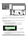
KEYPAD CONNECTION
DESCRIPTION OF TERMINALS
KEYPAD
PANEL
KPD
DTM
CKM
COM
+KPD
DTM
CKM
COM
COM CKM DTM KPD
Z1 – for detector Additional
Z2 – for detector system inputs
RS-232
Z1
Z2
anti-tampering contact
buzzer
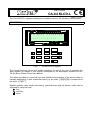
Figure 2. – LCD-L V1.2 keypad board.
The keypad connection to the main board and the use of the RS-232 port and the Z1, Z2
inputs are described in the manual „ CA-64 Alarm Control Panel - System Description and
Installation”.
The CA-64 KLCD-L keypad address is saved in the EEPROM non-volatile memory. It
can be programmed in two ways:
1. Directly (skipping the control panel service code):
• Turn off the keypad power supply and the data bus wires (CKM, DTM).
• Short the keypad terminals CKM and DTM.
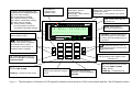
Turn on the keypad power supply. The following text will be displayed:
alarm
1
2
ALARM CONTROL PANEL CA-64 LCD
3
4
5
6
7 8
9 10 11 12 13 14 15 16
LCD-kpd Address
(n,0-7): _
17 18 19 20 21 22 23 24 25 26 27 28 29 30 3 1 32
service
1-32 33-64
trouble
armed
n=0...7,
current address of
the keypad
Figure 3. – Programming the keypad address
•
•
SATEL
Enter a new address within the 0-7 range. The keypad will confirm performance
of the function with four short and one long beeps. The address can be changed
again on pressing the [¾] key.
Connect the keypad to the control panel as required (CKM, DTM).
-2-
CA-64 KLCD-L