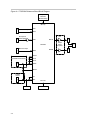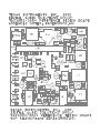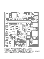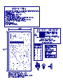
1
DAREF105 TAS3002/TAS3004 Reference Design Board User’s Guide June 2001 Digital Audio Products SLEU004 IMPORTANT NOTICE Texas Instruments and its subsidiaries (TI) reserve the right to make changes to their products or to discontinue any product or service without notice, and advise customers to obtain the latest version of relevant information to verify, before placing orders, that information being relied on is current and complete. All products are sold subject to the terms and conditions of sale supplied at the time of order acknowledgment, including those pertaining to warranty, patent infringement, and limitation of liability. TI warrants performance of its products to the specifications applicable at the time of sale in accordance with TI’s standard warranty. Testing and other quality control techniques are utilized to the extent TI deems necessary to support this warranty. Specific testing of all parameters of each device is not necessarily performed, except those mandated by government requirements. Customers are responsible for their applications using TI components. In order to minimize risks associated with the customer’s applications, adequate design and operating safeguards must be provided by the customer to minimize inherent or procedural hazards. TI assumes no liability for applications assistance or customer product design. TI does not warrant or represent that any license, either express or implied, is granted under any patent right, copyright, mask work right, or other intellectual property right of TI covering or relating to any combination, machine, or process in which such products or services might be or are used. TI’s publication of information regarding any third party’s products or services does not constitute TI’s approval, license, warranty or endorsement thereof. Reproduction of information in TI data books or data sheets is permissible only if reproduction is without alteration and is accompanied by all associated warranties, conditions, limitations and notices. Representation or reproduction of this information with alteration voids all warranties provided for an associated TI product or service, is an unfair and deceptive business practice, and TI is not responsible nor liable for any such use. Resale of TI’s products or services with statements different from or beyond the parameters stated by TI for that product or service voids all express and any implied warranties for the associated TI product or service, is an unfair and deceptive business practice, and TI is not responsible nor liable for any such use. Also see: Standard Terms and Conditions of Sale for Semiconductor Products. www.ti.com/sc/docs/stdterms.htm Mailing Address: Texas Instruments Post Office Box 655303 Dallas, Texas 75265 Copyright 2001, Texas Instruments Incorporated EVM IMPORTANT NOTICE Texas Instruments (TI) provides the enclosed product(s) under the following conditions: This evaluation kit being sold by TI is intended for use for ENGINEERING DEVELOPMENT OR EVALUATION PURPOSES ONLY and is not considered by TI to be fit for commercial use. As such, the goods being provided may not be complete in terms of required design-, marketing-, and/or manufacturing-related protective considerations, including product safety measures typically found in the end product incorporating the goods. As a prototype, this product does not fall within the scope of the European Union directive on electromagnetic compatibility and therefore may not meet the technical requirements of the directive. Should this evaluation kit not meet the specifications indicated in the EVM User’s Guide, the kit may be returned within 30 days from the date of delivery for a full refund. THE FOREGOING WARRANTY IS THE EXCLUSIVE WARRANTY MADE BY SELLER TO BUYER AND IS IN LIEU OF ALL OTHER WARRANTIES, EXPRESSED, IMPLIED, OR STATUTORY, INCLUDING ANY WARRANTY OF MERCHANTABILITY OR FITNESS FOR ANY PARTICULAR PURPOSE. The user assumes all responsibility and liability for proper and safe handling of the goods. Further, the user indemnifies TI from all claims arising from the handling or use of the goods. Please be aware that the products received may not be regulatory compliant or agency certified (FCC, UL, CE, etc.). Due to the open construction of the product, it is the user’s responsibility to take any and all appropriate precautions with regard to electrostatic discharge. EXCEPT TO THE EXTENT OF THE INDEMNITY SET FORTH ABOVE, NEITHER PARTY SHALL BE LIABLE TO THE OTHER FOR ANY INDIRECT, SPECIAL, INCIDENTAL, OR CONSEQUENTIAL DAMAGES. TI currently deals with a variety of customers for products, and therefore our arrangement with the user is not exclusive. TI assumes no liability for applications assistance, customer product design, software performance, or infringement of patents or services described herein. Please read the EVM User’s Guide and, specifically, the EVM Warnings and Restrictions notice in the EVM User’s Guide prior to handling the product. This notice contains important safety information about temperatures and voltages. For further safety concerns, please contact the TI application engineer. Persons handling the product must have electronics training and observe good laboratory practice standards. No license is granted under any patent right or other intellectual property right of TI covering or relating to any machine, process, or combination in which such TI products or services might be or are used. Mailing Address: Texas Instruments Post Office Box 655303 Dallas, Texas 75265 Copyright 2001, Texas Instruments Incorporated EVM WARNINGS AND RESTRICTIONS It is important to operate this EVM within the specified input and output ranges described in the EVM User’s Guide. Exceeding the specified input range may cause unexpected operation and/or irreversible damage to the EVM. If there are questions concerning the input range, please contact a TI field representative prior to connecting the input power. Applying loads outside of the specified output range may result in unintended operation and/or possible permanent damage to the EVM. Please consult the EVM User’s Guide prior to connecting any load to the EVM output. If there is uncertainty as to the load specification, please contact a TI field representative. During normal operation, some circuit components may have case temperatures greater than 60°C. The EVM is designed to operate properly with certain components above 60°C as long as the input and output ranges are maintained. These components include but are not limited to linear regulators, switching transistors, pass transistors, and current sense resistors. These types of devices can be identified using the EVM schematic located in the EVM User’s Guide. When placing measurement probes near these devices during operation, please be aware that these devices may be very warm to the touch. Mailing Address: Texas Instruments Post Office Box 655303 Dallas, Texas 75265 Copyright 2001, Texas Instruments Incorporated Related Documentation From Texas Instruments Preface Read This First About This Manual This user’s guide describes the operation of the TAS3002/TAS3004 reference design board, hereinafter referred to as the TAS3004 reference board. This document contains descriptions for board operations of a mono microphone or stereo application. Supplementally included on CD in the TAS3004 reference board kit is the software GUI documentation. This design is an example reference design that can be customized for specific applications. NOTE: In the default configuration, the TAS3004 reference board comes assembled with the TAS3004 chip. This board can also be used as is to evaluate the TAS3002, because the difference between the chips is minimal. How to Use This Manual This document contains the following chapters: - Chapter 1—Overview - Chapter 2—System Components - Chapter 3—Board Operation - Chapter 4—TAS3004 Reference Design Board—Block Diagram - Chapter 5—Utilization Overview Related Documentation From Texas Instruments - TAS1020A EVM User’s Guide, Literature No. SLEU002 - TAS3002 Digital Audio Processor With Codec data manual, Literature No. SLAS307B - TAS3004 Digital Audio Processor With Codec data manual, Literature No. SLAS325 v Trademarks - TLV2362 High-Performance Low-Voltage Operational Amplifiers data sheet, Literature No. SLOS195B - TPA0112 2-W Stereo Audio Power Amplifier With Four Selectable Gain Settings data sheet, Literature No. SLOS204B - TPS76433 Low-Power Low-Noise 150-mA Regulator, data sheet Literature No. SLVS180B Low-Dropout Linear - Software GUI release No. 2.0 or higher FCC Warning This equipment is intended for use in a laboratory test environment only. It generates, uses, and can radiate radio frequency energy and has not been tested for compliance with the limits of computing devices pursuant to subpart J of part 15 of FCC rules, which are designed to provide reasonable protection against radio frequency interference. Operation of this equipment in other environments may cause interference with radio communications, in which case the user at his own expense will be required to take whatever measures may be required to correct this interference. Trademarks Radio Shack and Optimus are trademarks of Tandy Corporation. Other trademarks are the property of their respective owners. vi Contents Contents 1 Overview . . . . . . . . . . . . . . . . . . . . . . . . . . . . . . . . . . . . . . . . . . . . . . . . . . . . . . . . . . . . . . . . . . . . . . . . 1.1 Modes of Operation . . . . . . . . . . . . . . . . . . . . . . . . . . . . . . . . . . . . . . . . . . . . . . . . . . . . . . . . . 1.2 Features . . . . . . . . . . . . . . . . . . . . . . . . . . . . . . . . . . . . . . . . . . . . . . . . . . . . . . . . . . . . . . . . . . 1.3 Environmental Working Conditions . . . . . . . . . . . . . . . . . . . . . . . . . . . . . . . . . . . . . . . . . . . . 1.4 Description of Inputs . . . . . . . . . . . . . . . . . . . . . . . . . . . . . . . . . . . . . . . . . . . . . . . . . . . . . . . . 1.5 Description of Outputs . . . . . . . . . . . . . . . . . . . . . . . . . . . . . . . . . . . . . . . . . . . . . . . . . . . . . . . 1.6 Power Supply . . . . . . . . . . . . . . . . . . . . . . . . . . . . . . . . . . . . . . . . . . . . . . . . . . . . . . . . . . . . . . 1-1 1-2 1-2 1-3 1-3 1-3 1-3 2 Systems Components . . . . . . . . . . . . . . . . . . . . . . . . . . . . . . . . . . . . . . . . . . . . . . . . . . . . . . . . . . . 2.1 Power Supplies and Decoupling . . . . . . . . . . . . . . . . . . . . . . . . . . . . . . . . . . . . . . . . . . . . . . 2.2 Microphone Amp and Bias . . . . . . . . . . . . . . . . . . . . . . . . . . . . . . . . . . . . . . . . . . . . . . . . . . . 2.3 Line Input . . . . . . . . . . . . . . . . . . . . . . . . . . . . . . . . . . . . . . . . . . . . . . . . . . . . . . . . . . . . . . . . . . 2.4 ADC/DAC Functions . . . . . . . . . . . . . . . . . . . . . . . . . . . . . . . . . . . . . . . . . . . . . . . . . . . . . . . . 2.5 TAS3004—Digital Equalization . . . . . . . . . . . . . . . . . . . . . . . . . . . . . . . . . . . . . . . . . . . . . . . 2.6 Clock Generation (Master Mode) . . . . . . . . . . . . . . . . . . . . . . . . . . . . . . . . . . . . . . . . . . . . . 2.7 Digital Audio Slave Mode . . . . . . . . . . . . . . . . . . . . . . . . . . . . . . . . . . . . . . . . . . . . . . . . . . . . 2.8 EEPROM . . . . . . . . . . . . . . . . . . . . . . . . . . . . . . . . . . . . . . . . . . . . . . . . . . . . . . . . . . . . . . . . . . 2-1 2-2 2-2 2-2 2-3 2-3 2-3 2-3 2-4 3 Board Operation . . . . . . . . . . . . . . . . . . . . . . . . . . . . . . . . . . . . . . . . . . . . . . . . . . . . . . . . . . . . . . . . . 3.1 Power-Up Sequence . . . . . . . . . . . . . . . . . . . . . . . . . . . . . . . . . . . . . . . . . . . . . . . . . . . . . . . . 3.2 Switch Functions for Digital Equalization . . . . . . . . . . . . . . . . . . . . . . . . . . . . . . . . . . . . . . . 3.3 Software GUI . . . . . . . . . . . . . . . . . . . . . . . . . . . . . . . . . . . . . . . . . . . . . . . . . . . . . . . . . . . . . . 3.4 Software Installation . . . . . . . . . . . . . . . . . . . . . . . . . . . . . . . . . . . . . . . . . . . . . . . . . . . . . . . . 3.4.1 PC Setup . . . . . . . . . . . . . . . . . . . . . . . . . . . . . . . . . . . . . . . . . . . . . . . . . . . . . . . . . . . 3.5 EQ GUI Start-Up . . . . . . . . . . . . . . . . . . . . . . . . . . . . . . . . . . . . . . . . . . . . . . . . . . . . . . . . . . . 3-1 3-2 3-2 3-3 3-3 3-3 3-4 4 TAS3004 Reference Board—Block Diagram . . . . . . . . . . . . . . . . . . . . . . . . . . . . . . . . . . . . . . . 4-1 5 Utilization Overview . . . . . . . . . . . . . . . . . . . . . . . . . . . . . . . . . . . . . . . . . . . . . . . . . . . . . . . . . . . . . 5-1 A Supplemental Information . . . . . . . . . . . . . . . . . . . . . . . . . . . . . . . . . . . . . . . . . . . . . . . . . . . . . . . . A-1 vii Contents Figures 3–1 3–2 4–1 Part I EQ GUI . . . . . . . . . . . . . . . . . . . . . . . . . . . . . . . . . . . . . . . . . . . . . . . . . . . . . . . . . . . . . . . . 3-5 Part II EQ GUI . . . . . . . . . . . . . . . . . . . . . . . . . . . . . . . . . . . . . . . . . . . . . . . . . . . . . . . . . . . . . . . . 3-6 TAS3004 Reference Board Block Diagram . . . . . . . . . . . . . . . . . . . . . . . . . . . . . . . . . . . . . . . 4-2 Tables 3–1 5–1 viii Switch Functions for Speaker Equalization . . . . . . . . . . . . . . . . . . . . . . . . . . . . . . . . . . . . . . . 3-3 EEPROM Programming Examples . . . . . . . . . . . . . . . . . . . . . . . . . . . . . . . . . . . . . . . . . . . . . . 5-1 Chapter 1 Overview The TAS3004 reference board demonstrates the operation of the digital equalization and the dramatic improvements that 32-bit digital audio signal processing can make on the quality of sound. Topic Page 1.1 Modes of Operation . . . . . . . . . . . . . . . . . . . . . . . . . . . . . . . . . . . . . . . . . . . 1-2 1.2 Features . . . . . . . . . . . . . . . . . . . . . . . . . . . . . . . . . . . . . . . . . . . . . . . . . . . . . 1-2 1.3 Environment Working Conditions . . . . . . . . . . . . . . . . . . . . . . . . . . . . . . 1-3 1.4 Description of Inputs . . . . . . . . . . . . . . . . . . . . . . . . . . . . . . . . . . . . . . . . . . 1-3 1.5 Description of Outputs . . . . . . . . . . . . . . . . . . . . . . . . . . . . . . . . . . . . . . . . 1-3 1.6 Power Supply . . . . . . . . . . . . . . . . . . . . . . . . . . . . . . . . . . . . . . . . . . . . . . . . . 1-3 Overview 1-1 Modes of Operation 1.1 Modes of Operation An analog stereo input signal is provided through a 3,5-mm. stereo jack. The left and right channels of the signal are filtered and converted via the analog-todigital converter in the TAS3004 into left and right digital signals. The digital signals are processed by the TAS3004 and then converted to analog via the digital-to-analog converter of the TAS3004. The analog left and right signals are amplified at the output stage and routed to the speaker and headphone output connectors. This provides drive for unamplified speakers via RCA jacks and stereo headphones via a 3,5-mm jack. The configuration of the TAS3004 is controlled via the software GUI (PC mode) or an onboard EEPROM (stand-alone mode). - PC Mode. The TAS3004 reference board is connected directly to a PC parallel port via a paddle board (DAREF106R1 board, included in kit). EQ GUI software is installed on the PC to exercise full control of the TAS3004. Menus allow control of volume, tone, dynamic range compression, EQ selection, mixer settings, format, I2C control, loudness, analog output selection, and EEPROM snapshot (for stand-alone mode). - Stand-Alone Mode. By burning a TAS3004 configuration snapshot into an EEPROM, volume, bass, treble and EQ selection control is maintained via momentary contact switches. See Section 5, EEPROM Utilization Overview, for a detailed description of how to burn the EEPROM data. In stand-alone mode, the embedded microcontroller in the TAS3004 is accessed via six GPIO pins to provide conttol over volume, bass, treble, and EQ selection. The switches and the EQ settings they provide are described in Section 3.2. The TAS3004 reference board can be configured as an IIS master or slave. It is shipped as an IIS master. This system receives and transmits digital data at a 48-kHz sampling frequency when it is used in the master mode. 1.2 Features The TAS3004 reference board has the following features: - TAS3004 stereo audio digital equalizer - Operation via either a pre-programmed EEPROM or via the PC through - 1-2 a paddle board (DAREF106) and GUI software program Six switches used to control the volume, bass, treble and equalization Mute control LED to indicate the analog input channel selected A 12.288-MHz master clock frequency Sampling rate of 48 kHz used for both 1-V rms stereo line inputs and analog stereo output signals A mono microphone input Stereo, 2-W/channel, differential-output, audio-power amplifier Operates from a 9-Vdc power supply Onboard 3.3-V and 5-V voltage regulators Digital input/output port compatible with the TAS1020A EVM Environmental Working Conditions 1.3 Environmental Working Conditions The circuit is designed to operate in a laboratory-type environment. 1.4 Description of Inputs The input to the TAS3004 reference board is a 3,5-mm stereo jack for both the microphone input and the line input. The line input signal required is a stereo analog signal. The analog input range is ground to a maximum of 1 V rms. The microphone input signal is designed to amplify and bias a three-wire electret microphone. The board initializes with analog input A (the line input) selected. To switch to the microphone input, the software GUI must be used. A 2-pin header is provided to facilitate the use of the second B input when in the mono mode. 1.5 Description of Outputs The headphone output is a 3,5-mm stereo jack. The headphone output is a stereo analog audio signal of 150 mW rms. The output is capable of driving 32-Ω headphones. The power amplifier output is via two RCA connectors. The power amplifier output signal is capable of driving 4- to 8-Ω speakers at up to 2 W/channel of power. 1.6 Power Supply The power supply for the speaker equalization board is 9 Vdc. The average current that the board draws is about 1.0 A when driving speakers and less than 150 mA when no speakers are connected. Overview 1-3 1-4 Chapter 2 Systems Components This chapter details individual circuits and functions within the TAS3004 reference board. Topic Page 2.1 Power Supplies and Decoupling . . . . . . . . . . . . . . . . . . . . . . . . . . . . . . . . 2-2 2.2 Microphone Amp and Bias . . . . . . . . . . . . . . . . . . . . . . . . . . . . . . . . . . . . . 2-2 2.3 Line Input . . . . . . . . . . . . . . . . . . . . . . . . . . . . . . . . . . . . . . . . . . . . . . . . . . . . 2-2 2.4 ADC/DAC Functions . . . . . . . . . . . . . . . . . . . . . . . . . . . . . . . . . . . . . . . . . . . 2-3 2.5 TAS3004—Digital Equalization . . . . . . . . . . . . . . . . . . . . . . . . . . . . . . . . . 2-3 2.6 Clock Generation (Master Mode) . . . . . . . . . . . . . . . . . . . . . . . . . . . . . . . 2-3 2.7 Digital Audio Slave Mode . . . . . . . . . . . . . . . . . . . . . . . . . . . . . . . . . . . . . . 2-3 2.8 EEPROM . . . . . . . . . . . . . . . . . . . . . . . . . . . . . . . . . . . . . . . . . . . . . . . . . . . . . 2-4 Systems Components 2-1 Power Supplies and Decoupling 2.1 Power Supplies and Decoupling The system uses a TL317 linear regulator to convert the 9-Vdc input to 5 Vdc to power the operational and power amplifiers, and a TPS76433 LDO to convert the 5-V power to 3.3 V to power the TAS3004. All power input pins are decoupled with 0.1 µF capacitors. 2.2 Microphone Amp and Bias The microphone input to the TAS3004 reference board is a low-level analog signal. A preamplifier made of a TLV2362, with a gain of approximately 30 dB, has been added to increase the amplitude to a level that can be accurately processed by the TAS3004. With a gain of 30 dB, a 28-mV signal produces a full-scale ADC output. Because most common microphones are electret, and must have a bias, the other amplifier in the TLV2362 is used as a voltage follower to generate this bias. The TLV2362 provides a bias voltage of 2.5 V. The microphone input is a 3,5-mm stereo connector, J3, on the TAS3004 reference board. The tip connection is for the microphone signal and the ring connection is the bias. When the TAS3004 reference board is initialized, the line input (analog input A) is the active input for this board. This circuit also functions with many dynamic microphones. 2.3 Line Input A stereo line input is provided through another 3,5-mm stereo connector (J2). The tip connection is the left channel and the ring connection is the right channel. Because the TAS3004 contains internal buffer amplifiers, only input capacitors are necessary for connection to the codec. The full-scale input signal to the TAS3004 is 0.7 V rms; therefore, an input attenuator has been added to reduce the input signal. PC sound cards usually produce 1 V rms and some consumer audio equipment can produce peaks up to 2 V rms. The input attenuator is designed to produce full-scale output when a 1-V rms signal is applied to the input. The line input can be selected by using the analog control panel with the software GUI. 2-2 ADC/DAC Functions 2.4 ADC/DAC Functions The TAS3004 reference board takes an analog stereo audio input (or a mono microphone signal) and converts the signal to digital so that digital equalization can be performed. The digital signal is then converted back into analog and sent to an external device. The analog-to-digital (A/D) and digital-to-analog (D/A) functions are performed by the TAS3004. The TAS3004 contains a stereo A/D and D/A 24-bit delta-sigma converter. The TAS3004 is capable of operating at a 48-kHz sampling frequency. The digital serial input option is set to programmable with the software GUI. When initialized, the device defaults to the 20-bit I2S mode. 2.5 TAS3004—Digital Equalization The TAS3004 stereo audio digital equalizer contains a 32-bit digital audio signal processor. It provides seven bands of parametric equalization, bass, treble and volume control, dynamic range compression, and dynamic loudness contour. 2.6 Clock Generation (Master Mode) The master clock for the TAS3004 reference board is provided by an external crystal connected to the TAS3004 internal oscillator. The oscillator runs at 12.288 MHz. The other digital audio timing signals are provided by circuitry in the TAS3004. 2.7 Digital Audio Slave Mode The TAS3004 reference board is shipped as a digital audio master. Its default mode of 20-bit I2S is used. A 12.288-MHz crystal is installed on the board. The digital output is connected to JB1, a TAS1020A EVM-compatible, 40-pin IDC connector. This output can be used to drive other devices if the interconnecting cable is kept short, about 6 inches. For use with the TAS1020A EVM or other digital mastering devices, the board must be reconfigured: 1) 2) 3) 4) 5) 6) 7) 8) 9) 10) 11) Remove the crystal (Y1) from its socket. Remove R21 Remove CY2 Add JP1 (supplied) Add JP2 (supplied) Unsolder and lift pin 7 of the TAS3004 (U1). This maps the TAS3004 to I2C address 6Ah. Install the 40-pin IDC connector (supplied) on the bottom of the board, if operation with the TAS1020A is desired. When using with a TAS1020A EVM, place the supplied piece of weather stripping over JB1 to prevent short circuits. Plug the TAS3004 reference board into JB2 of the TAS1020A EVM. Apply +9-Vdc power to the TAS3004 board. Follow instructions for the TAS1020A EVM in the TAS1020A EVM user’s guide. (TAS1020A firmware will have to be written to interface the two boards.) Systems Components 2-3 EEPROM 2.8 EEPROM The TAS3004 is capable of being configured by data loaded from an external EEPROM. This EEPROM is not shipped with the EVM because it contains specific speaker equalization and the target speakers are unknown. TI has several preprogrammed EEPROMs that contrain equalization code for speakers by various manufacturers. 2-4 Chapter 3 Board Operation This chapter details the operation of the TAS3004 reference board. Topic Page 3.1 Power-Up Sequence . . . . . . . . . . . . . . . . . . . . . . . . . . . . . . . . . . . . . . . . . . . 3-2 3.2 Switch Functions for Digital Equalization . . . . . . . . . . . . . . . . . . . . . . . 3-2 3.3 Software GUI . . . . . . . . . . . . . . . . . . . . . . . . . . . . . . . . . . . . . . . . . . . . . . . . . 3-3 3.4 Software Installation . . . . . . . . . . . . . . . . . . . . . . . . . . . . . . . . . . . . . . . . . . 3-3 3.5 EQ GUI Start-Up . . . . . . . . . . . . . . . . . . . . . . . . . . . . . . . . . . . . . . . . . . . . . . 3-4 Board Operation 3-1 Power-Up Sequence 3.1 Power-Up Sequence The power-up sequence for the speaker equalization board is very simple. 1) Insert either the EEPROM or the PS2 PC interface cable into the socket provided on the board. Verify the position of pin 1. 2) Connect +9 Vdc to the positive terminal of the power supply cable and connect a ground to the negative terminal. 3) Insert the 2,5-mm power connector into PJ1. 4) Turn on the power supply and verify the board draws a current of less than 150 mA. 5) Turn off the power. 6) Connect a 1-V rms analog signal to the 3,5-mm stereo input jack. This input can be provided either through a signal generator, a CD player, or other sound generation equipment. (Some CD players provide up to 2 V rms and may cause distortion.) 7) Connect the output to unamplified stereo speakers via the RCA output jacks. This output can be measured by a signal analyzer or played through speakers. Alternatively, connect stereo headphones to the 3,5-mm stereo headphone connector. Connecting the headphones also bypasses any digital equalization. 8) Turn on the power to the speaker equalization board and re-verify that the current draw is less than 150 mA after the board is initialized by the microcontroller or by the software GUI. 9) Turn on the power to the input and output devices. 10) Depending on the selected mode of operation—either through the EEPROM or through the software GUI program and the PS2 cable— introduce equalization to the input analog signal. The instructions for the EEPROM mode of operation are described in Section 3.2 and the instructions for the software start at Section 3.3. 3.2 Switch Functions for Digital Equalization When the speaker equalization board is used with an EEPROM, the six onboard switches allow the user to adjust the digital equalization, volume, bass and treble of the audio input signal. The EEPROM is preprogrammed with five different equalization effects— original or no EQ, flat EQ, jazz EQ, rock EQ and voice EQ. Because these equalizations were created for a specific type of speaker, they should be reprogrammed for your speakers or the user can obtain a pair of Optimus 5A8 speakers from Radio Shack. The EEPROM is also preprogrammed to increase or decrease the volume, bass and treble in 1 dB increments/ decrements for each push of the button. The switches on the board can be switched from EQ mode to volume/bass/treble mode by depressing SW3 and SW4 simultaneously. To return to the EQ mode, simultaneously depress SW1 and SW6. 3-2 Software GUI Table 3–1 describes the operation of the switches. Table 3–1. Switch Functions for Speaker Equalization SW6 Volume Up SW5 SW4 SW3 SW2 SW1 X Volume Dn X Bass Up X Bass Dn X Treble Up X Treble Dn X Shift 1 X Mute X EQ1 X X EQ2 X EQ3 X EQ4 X EQ5 X Shift 2 X X 3.3 Software GUI When the EEPROM used to configure the TAS3004 reference board is replaced by the PS2 cable, the configuration of the TAS3004 equalization can be done through the software GUI program from a PC. In the software-GUI operation mode, the six on-board switches are disabled and the seven bands of digital equalization, volume, bass and treble are controlled via the software. Refer to the Software GUI User’s Manual for instructions on how to use this feature. 3.4 Software Installation 3.4.1 PC Setup Set the parallel port on the PC into EPP mode. If EPP mode is not available, bidirectional or PS-2 mode often works. The parallel port configuration can be changed in the system setup during PC boot-up. - Installation from EQ Software Tools CD 1) Insert the EQ Software Tools CD. 2) Run Setup.exe from the root directory. 3) Follow the installation directions. Board Operation 3-3 EQ GUI Start-Up - Installation from DAREF105 EVM CD 1) Insert the DAREF105 EVM CD. 2) Run Setup.exe from the Software directory of the EVM CD. 3) Follow the installation directions. - Connection of PC to EVM for EQ GUI Operation 1) Connect the analog input from the CD, DVD player, or any alternative analog source to the TAS3004 reference board. 2) Connect a parallel cable between the parallel port on the computer and the DB25 connector on the TAS3004 reference board. Note: The parallel port cable can be replaced with the TI paddle board. In this document the term parallel cable means either the TI paddle board or the parallel-port cable. 3.5 EQ GUI Start-Up 1) Execute the software labeled EQ GUI from the directory where the software was loaded. 2) Load the TAS3004 EVM Demo.dat configuration file. The configuration files are all files with the file extension *.dat. The GUI prompts the user to enter a configuration file. The default file is EQ_GUI.dat. However, any of the other .dat files can be selected. 3) The GUI starts running if there are values loaded in the ALLPASS.EQ file. If the values loaded in the ALLPASS.EQ file are not defined, then Mute is the default for the volume and mixer. 4) Click the EQ Select button in the EQ GUI window [Figure 3–1 (a)]. Select the desired EQ file from one of the four windows in the EQ SELECT panel [Figure 3–1 (b)]. 5) Click the Mixer button in the EQ GUI window [Figure 3–1 (a)]. In the mixer panel [Figure 3–1 (c)], adjust the mixer settings to the desired level. 6) Click the Volume button in the EQ GUI window [Figure 3–1 (a)]. In the VOLUME panel [Figure 3–2 (g)], adjust the volume to the desired level. 7) Click the Tone button in the EQ GUI window [Figure 3–1 (a)]. In the TONE panel [Figure 3–2 (h)], adjust the bass and treble to the desired level. 8) The graphic equalizer can also be selected to adjust specific frequencies. Click the Graphic EQ button in the EQ GUI window [Figure 3–1 (a)]. Select the appropriate *.gr file from the Graphic Equalizer panel [Figure 3–2 (e)]. (Note: the Graphic Equalizer panel and the EQ SELECT panel do not operate simultaneously. The settings in the active window override the settings in the other window.) 9) Click the Analog D/M button in the EQ GUI window [(Figure 3–1 (a)]. Pick the proper input select in the Analog Control Register window [Figure 3–2 (f)]. 3-4 EQ GUI Start-Up Figure 3–1. Part I EQ GUI a b c Board Operation 3-5 EQ GUI Start-Up Figure 3–2. Part II EQ GUI d e f 3-6 g h Chapter 4 TAS3004 Reference Board—Block Diagram A functional block diagram of the TAS3004 reference board is shown in Figure 4–1. TAS3004 Reference Board—Block Diagram 4-1 Figure 4–1. TAS3004 Reference Board Block Diagram Crystal Oscillator (Master Mode) (MCLK) J2 Stereo Line Input J3 Microphone Preamplifier LINA RINA PA1 LINB Output Power Amplifier TAS3004 J7 Monaural Input TAS1020A EVM (TAS3004 Slave Mode) AOUTR RINB LRCLK SCLK MCLK JB1 SDIN2 RESET Paddle Board SCL J6 SDA IO0–IO5 EEPROM 4-2 J4 AOUTL GPI Switches J1 J5 Chapter 5 Utilization Overview The TAS3004 reference board is shipped in PC mode. It does not come with the EEPROM installed, because the EEPROM contains equalization coefficients specific to a set of speakers at the Texas Instruments digital audio lab. If the stand-alone mode of operation is desired, a 24LC04 or a 24LC16 EEPROM should be programmed and installed in the 8-pin DIP socket on the TAS3004 reference board. The 24LC04 EEPROM is used for a system containing two speakers (2.0) and up to five equalizations (normal, jazz, rock, etc.) with the same equalization for both the right and left channels. The 24LC16 EEPROM is used for a system containing two speakers (2.0) and up to five equalizations (normal, jazz, rock, etc.) with different equalization for both the right and left channels. Table 5–1. EEPROM Programming Examples Case EEPROM Bytes Mode 1 24LC04 4K (512×8) 2.0, Left EQ = Right EQ 2 24LC16 16K (2048×8) 2.0, Left EQ ≠ Right EQ The EEPROM function in the EQ GUI program makes both hex and binary copies of the settings of the GUI. The binary file (.bin) is used for programming the EEPROM, and the hex file is provided as a troubleshooting tool. The hex file contains identifiers that show the locations of the stored functions such as bass, treble, volume and equalization. When equalization has been determined using the other EQ GUI tools (see Section 3.5), click the EPROM button in the EQ GUI window [Figure 3–1 (a)]. Then click the Create Files button in the EPROM panel [Figure 3–2 (d)] to make the files. After programming the EEPROM, the EEPROM is installed in the EPROM socket on the TAS3004 reference board. At power on, the TAS3004 reads this EEPROM and is initialized with the data. The GUI program can still be used while the EEPROM is installed. Utilization Overview 5-1 Note: EEPROM Selection EEPROM part numbers vary with manufacturers. Ensure the EEPROM selected can operate at 3.3 V and has a 2-wire serial interface. Here are some examples of EEPROMs that work on the TAS3004 reference board: a. Atmel, AT24C04, AT24C16 b. MicroChip, 24LC04B, 24LC16B 5-2 Appendix A Supplemental Information This appendix contains the following items for the DAREF105 reference board: - Gerber files J Top silkscreen with hidden text J Top silkscreen without hidden text J Copper layer 1 J Copper layer 2 J Fab notes - Bill of materials - Schematic Supplemental Information A-1 UpDated: 15-Mar-01 DAREF105R2 TAS3002/TAS3004 Reference Design Board Rev. 1 Page 1 of 2 TEXAS INSTRUMENTS INTEGRATED CIRCUITS TYPE / SIZE Item Number DESCRIPTION REFERENCE DESIGNATORS MFG MFG PART NUMBER QTY 1 2 3 4 TAS3002CPFBTQFP48-PFB TLV2362PWR TSSOP8-PW TPA0112PWP HTSSOP24-PWP TPS76433DBV SOT23-DBV5 TAS3004CPFB TLV2362PWR TPA0112PWP TPS76433DBV U1 OA1 PA1 VR2 1 1 1 1 TI TI TI TI VENDOR PART NUMBER TAS3002CPFB TLV2362IPWR TPA0112PWP TPS76433DBV VENDOR TI TI TI TI CAPACITORS TYPE / SIZE Item Number DESCRIPTION REFERENCE DESIGNATORS MFG MFG PART NUMBER VENDOR PART NUMBER VENDOR ECJ-1VC1H150J ECU-V1H101JCV PCC150ACVTR-ND PCC101ACVTR-ND DIGIKEY DIGIKEY QTY 5 6 C0603 RC0603 15pfd 100pfd 7 8 9 10 CAP CERAMIC 470PF 50V 0603 SMD CAP 1200PF 50V CERAMIC 0603 SMD CAP 1500PF 50V CERAMIC 0603 SMD CAP 68000PF 16V CERM X7R 0603 11 12 13 14 CAP .1UF 16V CERAMIC X7R 0603 CAP 10000PF 50V CERM CHIP 0805 CAP .1UF 50V CERAMIC X7R 0805 CAP .15UF 25V CERAMIC X7R 0805 C0805 RC0805 16 17 C1206 RC1206 CAP .47UF 16V CERAMIC X7R 0805 CAP 1UF 16V CERAMIC Y5V 0805 CAP .33UF 25V CERAMIC X7R 1206 18 19 20 21 VSB10/16 VSB33/10 KGA15-16 FC100-25 CAP_VSB CAP_VSB C160060-020 C250100-030 CAP 10UF 16V VS ELECT SMD CAP 33UF 10V ELECT VS SMD KG RAD ALUM ELEC CAP 15MFD 16V CAP 100UF 25V ELECT FC RADIAL 15 CY1, CY2 C20, C58, C59 C3, C4, C5, C17, C28, C51, C60, C61, C62, C63, C64 C22, C23 C33 C34 2 Panasonic 3 Panasonic C9, C26, C29, C31, C32, C39, C45, C47, C49, C50, C53, C55, C57 C40 C42, C43 C15 C1, C2, C8, C11, C12, C13, C14, C16, C18, C19, C27 C30, C54, C56 C37 C25, C35, C36, C38, C41, C44, C46, C48, C52 C10, C21 C24 C6, C7 11 2 1 1 Panasonic Panasonic Panasonic Panasonic ECJ-1VC1H221J ECU-V1H122KBV ECU-V1H152KBV PCC1760TR-ND PCC471BVTR-ND PCC122BVTR-ND PCC152BVTR-ND PCC1760TR-ND DIGIKEY DIGIKEY DIGIKEY DIGIKEY 13 1 2 1 Panasonic Panasonic Panasonic Panasonic ECJ-1VB1C104K ECJ-2VB1H103K ECJ-2YB1H104K ECJ-2YB1E154K PCC1762TR-ND PCC103BNTR-ND PCC1840TR-ND PCC1830TR-ND DIGIKEY DIGIKEY DIGIKEY DIGIKEY 11 Panasonic 3 Panasonic 1 Panasonic ECJ-2YB1C474K ECJ-2VF1C105Z ECJ-3VB1E334K PCC1818TR-ND PCC1849TR-ND PCC1889TR-ND DIGIKEY DIGIKEY DIGIKEY ECE-V1CA100SR ECE-V1AA330WR ECE-A1CKG150 EEU-FC1E101S PCE3062TR-ND PCE3175TR-ND P911-ND P10269-ND DIGIKEY DIGIKEY DIGIKEY DIGIKEY MFG PART NUMBER VENDOR PART NUMBER VENDOR ERJ-3GSY0R00V ERJ-3EKF10R0V ERJ-3EKF27R4V P0.0GCT-ND P10.0HTR-ND P27.4HTR-ND DIGIKEY DIGIKEY DIGIKEY 9 2 1 2 Panasonic Panasonic Panasonic Panasonic RESISTORS Item Number 22 R0603 23 24 TYPE / SIZE DESCRIPTION REFERENCE DESIGNATORS MFG QTY RC0603 RES ZERO OHM 1/16W 5% 0603 SMD RES 10.0 OHM 1/16W 1% 0603 SMD RES 27.4 OHM 1/16W 1% 0603 SMD 25 26 27 28 29 30 31 32 RES 49.9 OHM 1/16W 1% 0603 SMD RES 332 OHM 1/16W 1% 0603 SMD RES 1.00K OHM 1/16W 1% 0603 SMD RES 1.50K OHM 1/16W 1% 0603 SMD RES 2.00K OHM 1/16W 1% 0603 SMD RES 2.49K OHM 1/16W 1% 0603 SMD RES 3.32K OHM 1/16W 1% 0603 SMD RES 4.22K OHM 1/16W 1% 0603 SMD 33 34 35 36 37 RES 4.99K OHM 1/16W 1% 0603 SMD RES 10.0K OHM 1/16W 1% 0603 SMD RES 15.0K OHM 1/16W 1% 0603 SMD RES 20.5K OHM 1/16W 1% 0603 SMD RES 24.9K OHM 1/16W 1% 0603 SMD R21, R63 R22 R23 R13, R14, R15, R17, R19, R20, R27, R43, R44, R57, R58 R5 R11, R12 R61, R62 R51, R53, R59 R3 R1 R52, R54, R55, R60 R2, R4, R24, R25, R26, R45, R46, R47, R48, R49, R50 R6, R41 R56 R35 R16, R18 2 Panasonic 1 Panasonic 1 Panasonic 11 1 2 2 3 1 1 4 Panasonic Panasonic Panasonic Panasonic Panasonic Panasonic Panasonic Panasonic ERJ-3EKF49R9V ERJ-3EKF3320V ERJ-3EKF1001V ERJ-3EKF1501V ERJ-3EKF2001V ERJ-3EKF2491V ERJ-3EKF3321V ERJ-3EKF4221V P49.9HTR-ND P332HTR-ND P1.00KHTR-ND P1.50KHTR-ND P2.00KHTR-ND P2.49KHTR-ND P3.32KHTR-ND P4.22KHTR-ND DIGIKEY DIGIKEY DIGIKEY DIGIKEY DIGIKEY DIGIKEY DIGIKEY DIGIKEY 11 2 1 1 2 Panasonic Panasonic Panasonic Panasonic Panasonic ERJ-3EKF4991V ERJ-3EKF1002V ERJ-3EKF1502V ERJ-3EKF2052V ERJ-3EKF2492V P4.99KHTR-ND P10.0KHTR-ND P15.0KHTR-ND P20.5KHTR-ND P24.9KHTR-ND DIGIKEY DIGIKEY DIGIKEY DIGIKEY DIGIKEY TAS3002/TAS3004 Reference Design Board Rev. 1 Page 2 of 2 RESISTORS -- CONTINUED TYPE / SIZE Item Number 38 39 DESCRIPTION REFERENCE DESIGNATORS MFG MFG PART NUMBER QTY 40 R0805 41 42 43 R1206 44 45 RC0805 RC1206 VENDOR PART NUMBER VENDOR RES 47.5K OHM 1/16W 1% 0603 SMD RES 249K OHM 1/16W 1% 0603 SMD R7, R9, R10, R28 R8 4 Panasonic 1 Panasonic ERJ-3EKF4752V ERJ-3EKF2493V P47.5KHTR-ND P249KHTR-ND DIGIKEY DIGIKEY RES 1.0 OHM 1/10W 5% 0805 SMD RES 215 OHM 1/10W 1% 0805 SMD RES 649 OHM 1/10W 1% 0805 SMD RES .1 OHM 1/8W 5% 1206 SMD RESISTOR 1.0 OHM 1/8W 5% 1206 RES 10 OHM 1/8W 1% 1206 SMD R40 R36 R39 R31, R32, R33 R30, R37, R38 R29, R34, R42 1 1 1 3 3 3 ERJ-6RQJ1R0V ERJ-6ENF2150V ERJ-6ENF6490V ERJ-8RSJR10V ERJ-8GEYJ1R0V ERJ-8ENF10R0V P1.0BTR-ND P215CTR-ND P649CTR-ND P.10PTR-ND P1.0ECT-ND P10.0FTR-ND DIGIKEY DIGIKEY DIGIKEY DIGIKEY DIGIKEY DIGIKEY MFG PART NUMBER VENDOR PART NUMBER VENDOR EXC-ML20A390U MI1206K310R-00 P10191TR-ND 240-1036-2-ND DIGIKEY DIGIKEY MFG PART NUMBER VENDOR PART NUMBER VENDOR 1 DIODES IINC MICROCHIP 1 Technology 1 Chicago Miniature 1N4148 LL4148DICT-ND DIGIKEY 24LC64-IP CMD15-21VGD/TR8 24LC64-I/P-ND L62305TR-ND DIGIKEY DIGIKEY 1 ZETEX 1 ZETEX 1 ECS National 1 Semiconductor 2N7002TA FMMT2222ATA ECS-122.8-S-4 2N7002TR-ND FMMT2222ATR-ND X174-ND DIGIKEY DIGIKEY DIGIKEY LM317EMP LM317EMPTR-ND DIGIKEY MFG PART NUMBER VENDOR PART NUMBER VENDOR 161-3503 CP-3535N-ND 16PJ097 CP-2460-ND S1011-02-ND SC1154-ND P8087STR-ND ED56083-ND S9000-ND MOUSER DIGIKEY MOUSER DIGIKEY DIGIKEY DIGIKEY DIGIKEY DIGIKEY DIGIKEY VENDOR PART NUMBER VENDOR SJ5303-7-ND DIGIKEY Panasonic Panasonic Panasonic Panasonic Panasonic Panasonic FERRITE BEADS TYPE / SIZE Item Number DESCRIPTION REFERENCE DESIGNATORS MFG QTY 46 FB0805 47 FB1206 FB0805 FB1206 BEAD CORE 39 OHM 4A 0805 SMD FERRITE SMT 1206 1.5A 31 OHMS FB3 FB2 1 Panasonic 1 STEWARD SEMICONDUCTORS TYPE / SIZE Item Number DESCRIPTION REFERENCE DESIGNATORS MFG QTY 48 LL4148 DL-35 1N4148, DIODE 100V 500MW FAST SWITCHING CR1 49 24LC64 50 LED_CMD15 DIP8 LED_CMD15 IC, 24LC64 LED GREEN DIFF 1206 SMD EPROM LED1 51 2N7002 SOT23-DBV3 52 FMMT2222A SOT23-DBV3 53 CRYSTAL-SCKT XTAL_SCKT TRANS 60V N CHANNEL MOSFET TO236 NFET1 Transistor, 2N2222A Q1 12.288MHz Y1 54 LM317EMP Voltage Regulator LM317 SOT-223 VR1 CONNECTORS Item Number 55 56 57 58 59 60 61 62 63 TYPE / SIZE DESCRIPTION REFERENCE DESIGNATORS MFG QTY MINI_ST_SW JACK_3.5MM-ST_SW 3.5mm Stereo SW MINI_STEREO JACK_3.5MM-ST CONN AUDIO JACK 3.5MM STEREO RCA_16PJ097 RCA_16PJ097 Left OUT, Right OUT PS2-6F PS2_CP2460 MINI-DIN RECEPT UNSHIELD 6 POS JMP2 SIP2_040 No Value PWRJACK_MINI JACK_RASH712P CONN 2.5MM PWRJACK HYBRID SMD SW_P8050 SW_P8050 SWITCH LIGHT TOUCH 240GF SMD 24LC64 DIP8 8 pin Dip socket SHORTING JUMPER TIN J1 J2(Line In), J3(Mic In) J4(Left Out), J5(Right Out) J6 JP1, JP2, JP3, J7(RINB) PJ1 S1, S2, S3, S4, S5, S6 EPROM JP3 (install after item 59 installed 1 2 2 1 4 1 6 1 1 DGS PRO Audio CUI STACK dGS PRO Audio CUI STACK Sullins Electronics SWITCHCRAFT Panasonic Mill-Max Sullins Electronics SJ-3535N 16PJ097 MD-60S PZC02SAAN RASH712 EVQ-PPDA25 110-13-308-41-001 STC02SYAN HARDWARE Item Number 64 TYPE / SIZE DESCRIPTION REFERENCE DESIGNATORS MFG MFG PART NUMBER QTY BUMPON HEMISPHERE .44X20 CLEAR Electronic Specialty 4 Market (3M) SJ-5303 (CLEAR) Mouser Electronics Authorized Distributor Click to View Pricing, Inventory, Delivery & Lifecycle Information: Texas Instruments: DA-REF105