1
AMAX panel 2000 / AMAX panel 2000 EN
F.01U.241.127
en
Installation Manual
F.01U.241.127
3
1
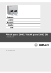
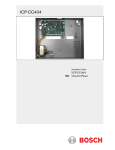
Graphics
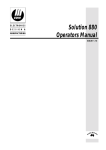
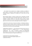
BOSCH AMAX panel 2000 OVERVIEW
ICP-AMAX-P-EN
ICP-AMAX-P
PSTN
B420/
DX4020
TELEPHONE
NETWORK
IP
or
BOSCH OPTION BUS
CENTRAL
MONITORING
STATION
GPRS
DX4020-G
IP
+
DX3010
IUI-AMAXLCD8
IUI-AMAXLED8
Robert Bosch Engineering and Business Solutions Limited
F.01U.241.127 | V2 | 2011.09
4
F.01U.241.127 | V2 | 2011.09
F.01U.241.127
Robert Bosch Engineering and Business Solutions Limited
AMAX panel 2000 / AMAX panel 2000 EN
Table of Contents | en
5
Table of Contents
1
Short Information
10
2
System Overview
11
2.1
AMAX Panel 2000 / AMAX Panel 2000 EN Features
11
3
Installation
12
3.1
Quick start
12
3.1.1
Setting date and time
13
3.1.2
AMAX Panel 2000 / AMAX Panel 2000 EN Zone Defaults
14
3.2
System Special Status Definition
14
3.3
Programming
14
3.3.1
Programming with the AMAX Keypad 2000
14
3.3.2
Programming with the ICP-EZPK Programming key
16
3.3.3
Installer’s Programming Command
16
3.3.4
Default the control panel with the hardware
16
3.4
Prerequisites for an EN-conform Setup of the System
17
4
User Guide
19
4.1
Arming the System
22
4.1.1
Arming in AWAY mode
22
4.1.2
Arming in STAY mode
23
4.1.3
Forced arming
23
4.2
Disarming the System
23
4.2.1
Disarming with CODE
23
4.2.2
Disarming with wireless control Key
23
4.2.3
Disarming with Key switch
23
4.3
Faults or Tamper conditions
23
4.3.1
System fault or tamper analysis Mode
24
4.4
Walk test mode
25
4.5
Event Memory Recall mode
25
4.6
Reset the Control Panel
25
4.7
Bypassing
26
4.7.1
Bypassing Zones
26
4.7.2
Bypassing Faults and Tamper conditions (Except Zone Tampers)
26
4.8
Enable / Disable the installers code
26
4.9
Change individual code
26
4.10
Keypad alarm operation commands
27
4.10.1
Duress alarm
27
4.10.2
Keypad panic alarm
27
4.10.3
Keypad fire alarm
27
4.10.4
Keypad medical alarm
27
4.11
Domestic Dialing
27
4.11.1
Domestic Dialing Alarm
27
4.11.2
Confirming the Domestic call
27
Robert Bosch Engineering and Business Solutions Limited Installation Manual
F.01U.241.127 | V2 | 2011.09
6
en | Table of Contents
5
AMAX panel 2000 / AMAX panel 2000 EN
Fault and Tamper Description
28
5.1
Accessory Modules Fail
29
5.1.1
Keypad 1 fail
29
5.1.2
Keypad 2 fail
29
5.1.3
DX3010 Fail
30
5.1.4
B420/DX4020/ITS-DX4020G Fail
30
5.2
Power Faults
30
5.2.1
AC Failure
30
5.2.2
Battery Failure
31
5.2.3
AUX Power Supply Fail
31
5.2.4
Bosch Option Bus Power Supply Fail
31
5.2.5
RF Power Supply Fail
31
5.3
Warning Device Failure
32
5.3.1
Warning Device 1 Disconnected
32
5.3.2
Warning Device 1 Short
32
5.3.3
Warning Device 2 Disconnected
32
5.3.4
Warning Device 2 Short
33
5.4
Telephone Line Fault
33
5.5
Date and Time Fail
33
5.6
Communication Failure
34
5.6.1
Communication Failure 1
34
5.6.2
Communication Failure 2
34
5.6.3
Communication Failure 3
34
5.6.4
Communication Failure 4
34
5.7
Tamper Condition
35
5.7.1
On Board Tamper
35
5.7.2
Keypad 1 Tamper
35
5.7.3
Keypad 2 Tamper
35
5.7.4
Keypad lock out
35
5.7.5
Sensor Tamper
36
5.7.6
Zone Tamper
36
5.8
External Fault
36
6
System Functions
38
6.1
Duress alarm
38
6.2
Siren Test
39
6.3
Fault and Tamper Analysis Mode
39
6.4
View date and time
39
6.5
Walk Test Mode
39
6.6
Event Memory Recall Mode
40
6.7
Reset panel/clear siren
40
6.8
Initiate a Modem Call
41
6.9
Send Test Report
41
6.10
Bypass Zones
41
6.11
Show Zone Type
41
6.12
Bypass all Faults and Tamper conditions (Except zone Tamper)
42
6.13
Enable Disable installer code user’s access
42
6.14
Change individual code
42
6.15
Setting date and time
42
F.01U.241.127 | V2 | 2011.09
Installation Manual Robert Bosch Engineering and Business Solutions Limited
AMAX panel 2000 / AMAX panel 2000 EN
Table of Contents | en
7
6.16
Add/delete User Codes
43
6.17
Add/delete Radio User Codes
43
6.18
Change Domestic Phone Number
44
6.19
Enter Programming Mode
44
6.20
Command 959 – Exit from installer’s programming mode without saving the programmed data
44
6.21
Command 960 – Exit from installer’s programming mode with saving the programming data
45
6.22
Command 961 – Reset the control panel to factory default settings
45
6.23
Command 962 – Copy the control panel memory to the programming key
45
6.24
Command 963 – Copy the programming key to the control panel
46
6.25
Command 999 – Display the software version number
46
6.26
Default the control panel with the hardware
46
7
System Informations 1
48
7.1
Zone Processing when arming
48
7.2
Zone Processing when disarming
48
7.3
Alarm processing
48
7.4
Software
49
7.4.1
Remote Connect
49
7.4.2
Remote Connect with Customer Control
49
7.4.3
Remote Connect with Callback Verification
49
7.4.4
Remotely Arm/Disarm System by Programming Softwares
50
7.5
Domestic Dialing
50
7.5.1
Domestic Dialing Function
50
7.6
Reporting Formats
50
7.6.1
Transmission Formats
50
7.6.2
Contact ID Format
50
7.6.3
CFSK Format
51
7.7
Dialer Information
51
7.7.1
Telephone number for Receiver 1 - 4/IP Address and Port
52
7.7.2
Other Network Programming Option
52
7.7.3
Report Transmission Sequence
53
7.7.4
Receiver 1 - 4 Transmission Format
53
7.7.5
Receiver 1 - 4 Subscriber ID Number
54
7.7.6
Call back Telephone Number
54
7.7.7
Ring Count
54
7.8
Access Codes
54
7.8.1
Installer Code
54
7.8.2
AMAX Panel 2000 / AMAX Panel 2000 EN User Codes
54
7.8.3
User Codes
55
8
System Informations 2
56
8.1
General overview on zones
56
8.1.1
Zone Inputs
56
8.1.2
Zone programming
57
8.1.3
Zone Types
57
8.1.4
Zone Bypass
61
8.1.5
Forced Arming
61
8.1.6
Silent Alarm
62
8.1.7
Zone Lockout
62
Robert Bosch Engineering and Business Solutions Limited Installation Manual
F.01U.241.127 | V2 | 2011.09
8
en | Table of Contents
AMAX panel 2000 / AMAX panel 2000 EN
8.1.8
Zone Tamper
62
8.1.9
Zone Fault
62
8.1.10
Zone Report
63
8.1.11
Zone Chime Mode
63
8.2
System Reporting Information
63
8.2.1
System Option Programming Definition
63
8.2.2
System Report and Memory Definition
64
8.2.3
Auto Test Report
67
8.3
System Event Memory Recall
67
8.3.1
Keypad Play Back System Events
67
8.4
Output Process
68
8.4.1
Output Events Option
68
8.4.2
Output Type
70
8.4.3
Output Duration
70
8.4.4
Keypad Buzzer Alarm Output
71
8.4.5
Optional Relay Output
71
8.4.6
On-board LED Indicator
71
8.4.7
DX3010 Support
71
8.5
System Event Time
71
8.5.1
Entry Time
71
8.5.2
Exit Time
71
8.5.3
Keypad Lockout Time
71
8.5.4
System Power Up Wait Time
71
8.5.5
AC MAINS Fail Wait Time
71
8.6
Optional Equipment
71
8.6.1
RE012 E 2-Channel Hand-Held Keyfob 433 MHz
72
8.6.2
WE800E 433 MHz RF Receiver
72
8.6.3
ICP-EZPK Programming Key
72
8.6.4
A-Link Plus Software
72
8.6.5
DX3010 8 Relay Module
72
8.6.6
B420/DX4020/ITS-DX4020G GSM GPRS Communication Module
72
8.6.7
IUI-AMAX-LED8 8 Zone LED Keypad
73
8.6.8
IUI- AMAX- LCD8 8 Zone LCD Keypad
73
9
Technical Data
74
9.1
Specification
74
9.2
Interface Description
76
9.2.1
Terminals Internal Description
76
9.2.2
Connector Interface Description
76
10
Programming sheets
77
10.1
Receiver Programming
77
10.1.1
Receiver Parameters
77
10.1.2
Domestic Programming
78
10.2
System Report Options Programming
78
10.2.1
Report Options
78
10.2.2
Test Report Time Interval Setting
79
10.3
System Functions Programming
79
10.3.1
Ring Count
79
F.01U.241.127 | V2 | 2011.09
Installation Manual Robert Bosch Engineering and Business Solutions Limited
AMAX panel 2000 / AMAX panel 2000 EN
Table of Contents | en
9
10.3.2
Remote Programming/Control
79
10.3.3
Call back Telephone Number
79
10.3.4
Exit Time
79
10.3.5
Entry Time
79
10.3.6
Keypad Lockout
79
10.3.7
Single Button STAY/AWAY ARM
80
10.3.8
Remote Arm by Software/Telephone
80
10.3.9
Arm by Keyfob
80
10.3.10
Force Arm as system is in trouble
80
10.3.11
Quick Emergency Alarm
80
10.3.12
Event Recall
80
10.3.13
OC1/Warning Device 1 Monitor
80
10.3.14
OC2/Warning Device 2 Monitor
80
10.3.15
Phone line Monitor
80
10.3.16
AC Fault Detect time
80
10.3.17
Battery Detect time
81
10.3.18
Event Record Count Per Set/Unset Period
81
10.3.19
Beep for Warning Devices
81
10.4
Zone Programming
81
10.5
Output Programming
84
10.5.1
Keypad Buzzer
84
10.5.2
Warning Device 1/ OC1 Output
84
10.5.3
Warning Device 2 / OC2 Output
84
10.5.4
Optional Relay Output / OC3
84
10.5.5
DX3010 Output
84
10.6
Installer/User Code Programming
86
10.6.1
Installer code # 0
86
10.6.2
User Codes
86
11
Troubleshooting
87
Glossary
89
Robert Bosch Engineering and Business Solutions Limited Installation Manual
F.01U.241.127 | V2 | 2011.09
10
1
en | Short Information
AMAX panel 2000 / AMAX panel 2000 EN
Short Information
Congratulations on selecting the AMAX Panel 2000/AMAX Panel 2000 EN for your installation.
Spend some time reading through this guide and familiarize yourself with the outstanding
operation and installation features of this system so that you can get the most from your unit.
In all aspects of planning, engineering, styling, operation, convenience and adaptability, we try
to anticipate your every possible requirement. Programming simplicity and speed are our
major considerations; we believe that our objectives have been attained.
This installation guide explains all aspects of programming the AMAX Panel 2000/AMAX Panel
2000 EN from factory default to final commissioning. All system parameters and options are
dealt with in detail, but adaptability differs with individuals. Each control panel can be
tailored to meet your requirements quickly and easily. The programming simplicity makes your
installation quick, accurate and rewarding.
As AMAX Panel 2000/AMAX Panel 2000 EN continue to improve over the years, they become
more powerful. We have addressed the needs of first-time users by maintaining simplicity in
the product and its installation guide, which enabled them in turn to evolve as "power users".
F.01U.241.127 | V2 | 2011.09
Installation Manual Robert Bosch Engineering and Business Solutions Limited
AMAX panel 2000 / AMAX panel 2000 EN
System Overview | en
2
System Overview
2.1
AMAX Panel 2000 / AMAX Panel 2000 EN Features
11
AMAX Panel 2000/AMAX Panel 2000 EN uses the latest in microprocessor technology to
provide you with useful features, and superior reliability and performance.
The control panel provides these features:
–
Eight programmable User Codes (1 - 8)
–
Eight programmable radio remote User Codes (9 - 16)
–
Eight programmable Burglary Zones
–
LED and LCD keypads
–
Support for up to four control stations
–
Separate programmable alarm and system information routing
–
Domestic dialing
–
Control station call back
–
CID and CFSK formats
–
B420 IP, BOSCH DX4020 IP and DX4020G GPRS modules
–
Telephone line monitor function
–
Keypad duress, panic, fire, and medical alarms
–
STAY Mode and AWAY Mode operation
–
RPS remote program upload/download
–
RPS remote control
–
Telephone remote arming
–
RE012E keyfob arming/disarming
–
Quick programming key
–
Dynamic battery testing
–
Entry/Exit warning beeper
–
AC Fail and system fault indicators
–
Fault inquiry and analysis
–
2 Programmable monitored siren output’s
–
Programmable on-board output
–
Relay output option
–
BOSCH DX3010 Octo relay module
–
Supports four wire smoke detector
–
Zone lockout
–
Zone testing and tamper
–
Zone bypass
–
Silent alarm
–
Walk test mode
–
Programmable test reports
–
254 event histories stored in non-volatile memory stamped with date and time
–
254 EN-event histories stored in separate non-volatile memory stamped with date and
time
Robert Bosch Engineering and Business Solutions Limited Installation Manual
F.01U.241.127 | V2 | 2011.09
12
en | Installation
AMAX panel 2000 / AMAX panel 2000 EN
3
Installation
3.1
Quick start
The following steps allow you to use the AMAX Panel 2000/AMAX Panel 2000 EN with factory
default values. To become familiar with programming AMAX Panel 2000/AMAX Panel 2000 EN,
read the information in Section 3.3 Programming, page 14.
1.
Connect auxiliary equipment
2.
After all wiring is complete, connect the AC plug pack and backup battery to the control
panel. The MAINS indicator lights signify AC mains supply is connected.
If any zone is unsealed when you power up the system, the corresponding zone indicator
is lit constantly.
Once you power up the panel, Date and Time has to be set.
All Faults and Tamper conditions have to be reset.
3.
Enter the default user code (2580) + (98) and press [#] to enable the installer’s access.
4.
Enter Date and Time. Refer to section 3.1.1 Setting Date and Time on page 10.
5.
Enter the default Installer Code (1234) + (958) and press [#]. Two beeps sound and the
STAY and AWAY indicators flash simultaneously to indicate that you have entered into
installer’s programming mode. Once you enter the installer’s programming mode, you are
automatically positioned at location 000, the first digit of IP address / Primary telephone
number for Receiver 1.
6.
Enter the IP address/Primary telephone number for Receiver 1 and then the port.
Programming a 15 in the telephone number indicates the end of the dialing sequence.
7.
Program any other required changes. Otherwise, factory default settings are used.
8.
Enter command [9 6 0] and press [#] to store the programming data and exit from
installer’s programming mode, a beep sounds and the STAY and AWAY indicators are
deactivated. The system is returned to the disarmed state and is ready for use. Refer to
Section 3.3.3 Installer’s Programming Command, page 16
9.
F.01U.241.127 | V2 | 2011.09
Enter the default user code (2580) and (6) and press [#] to reset the panel.
Installation Manual Robert Bosch Engineering and Business Solutions Limited
AMAX panel 2000 / AMAX panel 2000 EN
Installation | en
13
3671
5 5
7
ICP-AMAX-P
ICP-AMAX-P-EN
7
:((3RUW
7DPSHU
6ZLWFK3RUW
3
Z8
1
3
COM
Z7
3
Z6
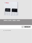
,QVWDOODWLRQ&RGH5HVWRUH
2
1 Tamper Switch
2 Zone Switch
3 EOL 2,2 k
2
COM
Z5
=RQH
,&3(=3.
3URJUDP.H\3RUW
3
Z4
2
COM
Z3
Z2
COM
Z1
,&3$0$;/&'
,&3$0$;/('
Y
%RVFK
%XV
)DVW᧶'LDOOLQJLQGLFDWLRQDQGSRZHU
RQWRUHVWRUHLQVWDOODWLRQFRGH
6ORZ1RUPDORSHUDWLRQLQGLFDWLRQ
B
2XWSXW
3RUW
GND
+12V
';
PD[RXWSXW
FXUUHQWP$
_
OC2
OC3
OC+
PD[LPXPRXWSXWFXUUHQW
2&9'&#P$
OC1
_
OC+
+
-
)RURSHUDWLRQVDIHW\
WKHJURXQGWHUPLQDOV
PXVWEHFRQQHFWHG
%DWWHU\
+
PD[LPXPRXWSXWFXUUHQW᧶
2&9'&#P$
2&9'&#P$
9$K
AC
AC
9$	$
7UDQVIRUPHU
3RZHU
+
5HIHUWRUHODWHG8VHU0DQXDOIRU
';%,76';*
';
';%
,76';*
R
$X[
3RZHU
/('
G
Keypad 1
Keypad 2
1
1
/
/
5LVNRIVKRFNLI1/
RULVFRQQHFWHG
LQFRUUHFWO\
Fuse 500 mA
9a+]
P$
Figure 3.1 Wiring Diagram
3.1.1
Setting date and time
Set the date and time after powering up the system, otherwise Date and Time Default to
factory settings.
1.
Enter the installer code +955 and press [#]. Two beeps sound, the STAY and AWAY
indicators flash and date + time is shown in the format YYMMDD HHMM.
2.
Enter the year, month, day, hour and minute in YY, MM, DD, HH, MM format and press [#].
Use 24:00 hour format when programming the hour of the day. A beep sounds and the
STAY and AWAY indicators are deactivated. If a long beep sounds, it indicates an
erroneous entry of date and time.
3.
If operation is not carried out within 240 seconds after entering the date and time setting
interface, the system will automatically exit from the setting.
Robert Bosch Engineering and Business Solutions Limited Installation Manual
F.01U.241.127 | V2 | 2011.09
14
en | Installation
AMAX panel 2000 / AMAX panel 2000 EN
Example
To set the date and time for the 25th of December 2010 at 10:30PM, enter:
[Installer CODE + 955][#] break until time is shown [1 0 1 2 2 5 2 2 3 0][#]
3.1.2
AMAX Panel 2000 / AMAX Panel 2000 EN Zone Defaults
The default zone settings for the control panel are listed in Table 3.1, Page 14. You can
program zones 1 to 8 to any of the zone types. Refer to Table 10.4, Page 81 for the zone type
you can select.
Zone
Zone type
Zone
Zone type
1
Delay
5
Instant
2
Follower
6
Instant
3
Instant
7
Instant
4
Instant
8
Instant
Table 3.1
3.2
Zone defaults
System Special Status Definition
–
When the AC power voltage is lower than 9V±5%, the system will not detect/send out the
zone status report to CMS.
–
When the AC power voltage is more than 9V±5%, the system will wait for 1 minute to
back up the normal work while in a stable work status.
3.3
Programming
The control panel programming options are stored in a non-volatile flash memory. This
memory has all relevant configurations and user-specific data even after a total power loss.
Because the data retention time is quite long without power, reprogramming is not required
after powering up the control panel.
You can change data as many times as required without any additional specialized equipment.
The memory is organized in locations, each of which holds the data for a specific function.
NOTICE!
0 is the minimum value and 15 is the maximum value that can be programmed into any
location.
In general, the entire programming sequence consists of selecting the required location and
entering or changing the current data. Repeat this procedure until you program all the
required data.
The installer code turns active only when it’s enabled by a user. You cannot enter installer’s
programming mode if the system is armed, or during siren run time.
You can program the AMAX Panel 2000 / AMAX Panel 2000 EN using any of these three
devices:
3.3.1
–
Keypads
–
A - Link - Plus Upload/download software
–
CP-EZPK Programming key
Programming with the AMAX Keypad 2000
To program the control panel using the keypad, the system must be disarmed with no alarm
memory present and installer access must be enabled.
To access installer’s programming mode:
F.01U.241.127 | V2 | 2011.09
Installation Manual Robert Bosch Engineering and Business Solutions Limited
AMAX panel 2000 / AMAX panel 2000 EN
Installation | en
15
Enter the four-digit installer code (the factory default is 1234) + (958) and press [#] .
Two beeps sound and both the STAY and the AWAY indicators flash simultaneously to
indicate that you have entered into installer’s programming mode.
Once you enter into installer’s programming mode, you are automatially positioned at location
000, the first digit of the IP Address/ primary telephone number for receiver 1. The keypad
indicators display the current data stored in this location.
Data
Zone Indicators
Value
1
2
3
4
5
6
7
8
Mains
0
1
X
2
X
3
X
4
X
5
X
6
X
7
X
8
9
X
X
X
10
11
X
X
12
X
X
13
X
X
14
X
X
15
X
X
X
Table 3.2 Keypad Indicators
To move to a different programming location:
Enter the location number and press [#] .
For example, press [1 7][#] to automatically position you at the beginning of the subscriber ID
number 17 for receiver 1. The data stored in the new location appears.
To move to the next location:
Press [#] .
For example, if you are currently positioned at location 017, press [#] to move to location
018.
To move to the previous location:
Press [*] .
For example, if you are positioned at location 018, press [*] to move back to Location 017.
To change data in the current location:
Enter the new value (0 - 15) and press [*] .
The data is stored and you remain positioned at the same location. The keypad indicators
display the new value (for example, if you enter [1 4] and press [*] , the zone 4 and MAINS
indicators are lit).
To exit from installer’s programming mode + save data:
Enter command [9 6 0] and press [#].
Two beeps sound and the STAY and AWAY indicators are deactivated. The system returns to
the disarmed state and is now ready for use.
Robert Bosch Engineering and Business Solutions Limited Installation Manual
F.01U.241.127 | V2 | 2011.09
16
en | Installation
AMAX panel 2000 / AMAX panel 2000 EN
Refer to Section 3.3.3 Installer’s Programming Command, page 16 for more information about
using installer’s programming mode.
NOTICE!
Enter command [9 5 9] [#] to exit if the setting does not need to be saved.
3.3.2
Programming with the ICP-EZPK Programming key
The ICP-EZPK Programming key allows you to save or copy programming information from
your control panel. After saving information in the programming key, you can easily program
other AMAX Panel 2000 / AMAX Panel 2000 EN with the same programming data. You can also
use the programming key to back up existing information.
If you have a new programming key, enter installer’s programming mode, program the system
as required, and connect the programming key to the control panel.
To connect the programming key:
Locate the socket labeled PROGRAMMING KEY at the top of the printed circuit board (PCB) .
Observe the triangular markings on the PCB and align them with the markings on the
programming key.
For example: to copy data from the control panel to the programming key:
1.
Enter the installer code (the default is 1234) + (958) and press [#] to enter into
installer’s programming mode.
2.
Enter [9 6 2 #].
Refer to Section 6.23 Command 962 – Copy the control panel memory to the programming
key, page 45.
3.
4.
Enter [9 6 0 #] to exit from installer’s programming mode.
The system resets and returns to the disarmed state. And the programming key becomes
your standard data pattern for future control panel programming.
CAUTION!
If you do not enter installer’s programming mode first, which connects the blank ICP-EZPK
Programming key to the control panel, no data can be uploaded /downloaded.
An unknown error may be caused if the installer’s programming mode is not exited before
removing the programming key.
3.3.3
Installer’s Programming Command
There are six commands that you can use in installer’s programming mode. To issue the
command, enter the command number and press [#].(CMD 959-999). Refer to
Section 6 System Functions, page 38
3.3.4
Default the control panel with the hardware
If the installer code is lost, the default pads on PCB can be used to default the control panel.
1.
2.
Disconnect the AC MAINS supply and the backup battery from the control panel.
Short the default pads. The default pads is located on the right top of the PCB next to the
PROGRAMMING KEY socket.
3.
Reconnect the power supply to the control panel.
4.
If the LED on the control panel PCS flashes fast, release the default pads about 5
seconds later.
5.
The control panel is successfully defaulted to the default Installer und User Code, other
parameters are not defaulted.
F.01U.241.127 | V2 | 2011.09
Installation Manual Robert Bosch Engineering and Business Solutions Limited
AMAX panel 2000 / AMAX panel 2000 EN
6.
Installation | en
17
If the LED on the control panel PCB does not fast flash, the factory default was
unsuccessful.
3.4
Prerequisites for an EN-conform Setup of the System
–
System must be mounted inside the monitored area on a stable surface
–
Keypads must be mounted to the inner side of the monitored area
–
Once the system is tested and ready to use, Enclosure Door and Keypads must be
–
Two external Warning Devices must be connected to the System
–
The Dialer must be connected to a Central Monitoring Station
–
A 12V/7AH Battery must be connected to the System
–
The Maximum Current of all Components together (PCB=lOOmA, lCP-KP8L=18mA,
–
The lock can only be used in an non EN setup.
–
The panel must be programmed with the EN settings indicated on the programming
secured with screws
ICPKP8 =24mA) should not exceed 550mA
sheet. When the panel is set without EN parameters, the EN Indication (Label) must be
removed.
Instructions to modify the IUI-AMAX-LED8 and the IUI-AMAX-LCD8 Keypad to meet the EN
requirements
1. Open the Keypad
2. Remove the PCB (open the two screws on the PCB).
3. Remove the rubber
Figure 3.2
4. Apply one drop of Instant Adhesive Loctite 401 on each side of the window.
(See Figure 3.3 and Figure 3.4)
The Adhesive must be applied to the Window and to the Enclosure
Robert Bosch Engineering and Business Solutions Limited Installation Manual
F.01U.241.127 | V2 | 2011.09
18
en | Installation
AMAX panel 2000 / AMAX panel 2000 EN
Figure 3.3
Figure 3.4
5. Reassemble the Keypad (it’s now ready for use in you’re EN setup)
F.01U.241.127 | V2 | 2011.09
Installation Manual Robert Bosch Engineering and Business Solutions Limited
AMAX panel 2000 / AMAX panel 2000 EN
4
User Guide | en
19
User Guide
ICP-AMAX - LED8-8 Zone LED Keypad
ICP-AMAX-LCD8 - 8 Zone LCD Keypad
Quick keypad operation instructions
Arming
AWAY arm
[code] + [#] / [#] (quick arming)
STAY arm
[code] + [*] / [*] (quick arming)
Disarming
Disarm
[code] + [#]
Other Commands
Fault and
[code] + [2] [#]
Tamper Analysis
Walk test
[code] + [4] [#]
Event recall
[code] + [5] [#]
System Reset
[code] + [6] [#]
Bypassing zones [code] + [9] [#] [zone] + [*] [#]
Bypassing Faults [code] + [97] [#]
and Tamper
conditions
Enable/Disable
Enable = [code] + [98] [#] Disable = [code] + [98] [*]
Installer code
Change
[code] + [99] [#] [newcode] [#]
individual code
Alarm Commands
Duress alarm
[code] + [0] [#]
Emergency
Simultaneously press and hold [1] and [3] or [*] and [#]
alarm
Fire alarm
Simultaneously press and hold [4] and [6]
Medical alarm
Simultaneously press and hold [7] and [9]
Default user code = 2580
Table 4.1 Quick keypad operation instructions
Robert Bosch Engineering and Business Solutions Limited Installation Manual
F.01U.241.127 | V2 | 2011.09
20
en | User Guide
AMAX panel 2000 / AMAX panel 2000 EN
Keypad Indicators
LCD keypad
LED keypad
indicator icons
indicator lights
Zone (1-8)
1 2 3 ….
AWAY
Status
Definition
on
Zone is triggered.
off
Zone is normal.
Fast flash (0.25 seconds lights on/
Zone was alarmed or is in alarm
0.25 seconds lights off)
status.
Slow flash (1 second lights on/1
Zone is manually bypassed or
second lights off)
interior Zone is in STAY ARM mode.
on
System is armed in AWAY mode.
off
System not armed in AWAY mode.
Slow flash (1 second lights on/1
Exit time.
second lights off)
Fast flash (0.25 seconds lights on/
Programming mode or Code
0.25 seconds lights off)
function mode. STAY indicator
flashes simultaneously.
STAY
on
System is armed in STAY mode.
off
System not armed in STAY mode.
Slow flash (1 second lights on/1
Exit time.
second lights off)
Fast flash (0.25 seconds lights on/
Programming mode or Code
0.25 seconds lights off)
function mode. AWAY indicator
flashes simultaneously.
When bypass function is
performed, the STAY indicator only
flashes.
MAINS
on
AC main power is normal.
Slow flash (1 second lights on/1
AC main power supply failed.
second lights off)
FAULTS
on
System fault or Tamper condition
is present.
off
System is in normal status.
Flashes
System fault or Tamper condition
must be acknowledged.
on
Table 4.2
F.01U.241.127 | V2 | 2011.09
System is disarmed.
Keypad Indicators
Installation Manual Robert Bosch Engineering and Business Solutions Limited
AMAX panel 2000 / AMAX panel 2000 EN
User Guide | en
21
Keypad sounds
Sound indicator Definition
One short beep
A keypad button has been pressed.
One single one-
The requested operation is refused. Incorrect operation signal.
second beep
Two short beeps The system accepted the code. The system executed the requested
function.
One short beep
In walk test mode.
per second
One short beep
Exit time started.
every two
seconds
Continued
–
Last 10s on exit time
sound
–
Keypad fault/tamper sound (fault/tamper to be acknowledged)
–
Keypad alarm sound
Continuous 0.5
Entry delay time (until alarm ends or system is disarmed).
second beep,
stops 0.5
seconds
Table 4.3 Keypad sounds
Zone description
Zone 1 ______________________________________________________
Zone 2 ______________________________________________________
Zone 3 ______________________________________________________
Zone 4 ______________________________________________________
Zone 5 ______________________________________________________
Zone 6 ______________________________________________________
Zone 7 ______________________________________________________
Zone 8 ______________________________________________________
Exit Time ___________________________________________________ sec
Entry Time _________________________________________________ sec
User Code Names
Code 1 _____________________________________________________
Code 2 _____________________________________________________
Code 3 _____________________________________________________
Code 4 _____________________________________________________
Code 5 _____________________________________________________
Code 6 _____________________________________________________
Code 7 _____________________________________________________
Code 8 _____________________________________________________
Code 9 _______________________________________________________ Keyfob 1
Code 10 _____________________________________________________ Keyfob 2
Code 11 _____________________________________________________ Keyfob 3
Code 12 _____________________________________________________ Keyfob 4
Code 13 _____________________________________________________ Keyfob 5
Robert Bosch Engineering and Business Solutions Limited Installation Manual
F.01U.241.127 | V2 | 2011.09
22
en | User Guide
AMAX panel 2000 / AMAX panel 2000 EN
Code 14 _____________________________________________________ Keyfob 6
Code 15 _____________________________________________________ Keyfob 7
Code 16 _____________________________________________________ Keyfob 8
4.1
Arming the System
NOTICE!
When the number of incorrect code entries on the keypad reaches a specified number, the
keypad will automatically lock for 180 seconds and alarm is reported.If the keypad is idle for 4
minutes, the system will automatically exit from any operational mode.
4.1.1
Arming in AWAY mode
Arming the system in AWAY Mode is normally performed when you leave the premises and
require that all zones are activated in a ready state to detect an intrusion.
4.1.1.1 Keypad arming
The system can be set to AWAY mode in two different ways.
To arm the System in AWAY mode (method 1)
Enter your code and press [#].
Two beeps sound, the AWAY indicator flashes slow, and exit time starts. After exit time, the
AWAY indicator turns is lit.
To arm the System in AWAY mode (method 2)
Press and hold [#] until it beeps twice.
The AWAY indicator flashes slow, and exit time starts. After exit time, the AWAY indicator is lit.
Please contact your installer to enable/disable this function.
4.1.1.2 Telephone remote arming
The user dials the control panel number. The control panel answers the call and issues a long
beep. After the long beep, the user must press the [#] key. When the Panel receives the signal
it will confirm the arming of the control panel with a high tone.
Please contact your installer to enable/disable this function.
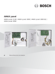
4.1.1.3 Arming in AWAY mode with wireless remote control Key
Press and hold the Arming Button until two beeps sound on the remote keypad and the AWAY
indicator flashes slow. Exit time starts. After exit time, the AWAY indicator is lit.
RE012E:2 standard wireless remote control key
1
2
3
1 –Button 1: Arm in AWAY mode
2 –Button 2: Disarm
3 –Button 1 and 2: Press both buttons at the same time to activate Panic alarm
F.01U.241.127 | V2 | 2011.09
Installation Manual Robert Bosch Engineering and Business Solutions Limited
AMAX panel 2000 / AMAX panel 2000 EN
User Guide | en
23
4.1.1.4 Key switch arming
Users can use a key switch to Arm and Disarm the system. When the Key switch is activated,
the AWAY indicator flashes slow and exit time starts. After exit time, the AWAY indicator is lit.
When the Key switch is deactivated, the system is disarmed and Away indicator is off.
4.1.2
Arming in STAY mode
STAY Mode is used when you need to arm the perimeter and unused areas of the premises to
detect a would-be intruder, while at the same time being able to move freely within an area
that is automatically isolated
There are two methods to arm your system in STAY Mode
To arm the system in STAY mode (method 1)
Enter your code and press [#].
Two beeps sound, the STAY indicator flashes slow and exit time starts. After exit time, the
STAY indicator is lit.
The lights corresponding to all zones programmed as automatically isolated zones (Interior
Instant Zone) begin to flash and continue until the exit time is finished.
To arm the system in STAY mode (method 2)
Press and hold [#] for 3 seconds.
When two beeps sound, release the button.
The STAY indicator flashes slow and exit time starts. After exit time, the STAY indicator is on.
Please contact your installer to enable/disable this function.
4.1.3
Forced arming
Arming the system when a zone is not sealed is known as forced arming. If the AWAY indicator
does not glow, and if a long beep sounds when you attempt to arm the system in AWAY Mode,
then forced arming is not permitted. If this is the case, then you will have to seal all zones or
manually isolate them before you can arm the system.
Please contact your installer to enable/disable this function.
4.2
Disarming the System
4.2.1
Disarming with CODE
Enter your code and press [#] .Two beeps sound and the AWAY or STAY indicator is
extinguished.
4.2.2
Disarming with wireless control Key
Press and hold the Disarming Button. Two beeps sound and the AWAY or STAY indicator is
extinguished.
4.2.3
Disarming with Key switch
When the Key switch is deactivated, the system is disarmed and the AWAY or STAY indicator is
extinguished.
4.3
Faults or Tamper conditions
Whenever a system fault or tamper condition occurs, the FAULT or MAINS indicator flashes
and the keypad beeps.
Robert Bosch Engineering and Business Solutions Limited Installation Manual
F.01U.241.127 | V2 | 2011.09
24
en | User Guide
AMAX panel 2000 / AMAX panel 2000 EN
NOTICE!
Operation can be carried out only in disarmed status.
4.3.1
System fault or tamper analysis Mode
To enter fault or tamper analysis mode for determining a system fault or tamper condition:
1.
Enter your Code and [2] and press [#]. Two beeps sound.The FAULT indicator remains lit
and the STAY and AWAY indicators flash. The lit zone indicators indicate the type of fault
or tamper condition that occurred.
2.
For a multi-level menu, enter the corresponding number to enter the submenu, press [ 0
] key to return to the main menu.
3.
To exit from Fault and Tamper Analysis Mode, press [#] . The STAY and AWAY indicators
are extinguished and the FAULT indicator remains lit, and the keypad stops the beep.
1
2
3
Accessory Modules Fail
1
Keypad 1 fail
2
Keypad 2 fail
3
DX 3010 Fail
4
B420/DX 4020 /-G Fail
Power Faults
1
AC Fault
2
Fault Battery
3
Aux Power Supply Fault
4
Bosch Option Bus Power Fault
5
RF Power Fault
Warning Device Failure List
1
Warning Device 1 Disconnected
2
Warning Device 1 Short
3
Warning Device 2 Disconnected
4
Warning Device 2 Short
4
Telephone Line Fail
5
Date and Time Fail
6
Communications failure
7
8
F.01U.241.127 | V2 | 2011.09
1
Communication Failure 1
2
Communication Failure 2
3
Communication Failure 3
4
Communication Failure 4
Tamper
1
On board Tamper
2
Keypad 1 Tamper
3
Keypad 2 Tamper
4
Keypad Lock out
5
Sensor Tamper (Zone 1-8)
6
Tamper Zone (Zone 1-8)
External Fault
Installation Manual Robert Bosch Engineering and Business Solutions Limited
AMAX panel 2000 / AMAX panel 2000 EN
4.4
User Guide | en
25
Walk test mode
This function allows code holders to test detection devices to ensure they are functioning
correctly. Before activating Walk test Mode, bypass any zones that are not required for
testing.
During the walk test, no walk test report is sent out to the control panel system.
To enter into Walk test Mode:
1.
Enter your Code + [4] and press [#].
Two beeps sound and the STAY and AWAY indicators flash. The keypad beeps once per
second when walk test mode is active.
2.
Unseal and seal the zones to be tested.
The keypad sounds one second beep and the siren sounds one beep each time when a
Zone status is changed.
4.5
Event Memory Recall mode
This function allows you to playback the last 254 system events that occurred.
Event Memory recall mode reports all alarms and each arming or disarming of the system and
helps in troubleshooting system faults.
The events are shown using the keypad indicators. Defined events are shown using keypad
indicators.
To enter Event memory Recall mode:
Enter your code + [5] and press #. Two beeps sound. The events are played back by the
keypad indicators in reverse chronological orer.
Example:
If the events occurred in the following order:
Sequence
Event
1
System armed in AWAY mode
2
Alarm in Zone 3
3
Alarm in Zone 4
4
System disarmed
The alarm memory is played back in this order:
Sequence
Indication
Event
1
All indicators off
System disarmed
2
Zone 4 and AWAY indicators light
Alarm in Zone 4
3
Zone 3 and AWAY indicators light
Alarm in Zone 3
4
AWAY indicator lights
System armed in AWAY mode
Each event is indicated by a beep and a lit indicator.
Resetting a disarmed 24-Hour alarm is indicated by a beep only.
After the last event, two beeps sound to indicate the end of the playback.
You can stop the replay at anytime by pressing [#].
If the system is armed in STAY mode, the STAY indicator shows the event memory playback.
If the control panel is powered down the memory of all events is saved.
4.6
Reset the Control Panel
This function allows code holders to reset all Alarm Faults and Tamper conditions.
Robert Bosch Engineering and Business Solutions Limited Installation Manual
F.01U.241.127 | V2 | 2011.09
26
en | User Guide
AMAX panel 2000 / AMAX panel 2000 EN
Enter your code and then press [6] [#].
The keypad beeps twice and the signal is eliminated.
NOTICE!
You can reset alarms, faults or tamper conditions, only when they are not active anymore.
4.7
Bypassing
4.7.1
Bypassing Zones
By bypassing Zones, one or more zones are disabled for one arming cycle. After bypassing a
zone, you can arm the system even when a zone is in alarm state.
How to bypass a zone
1.
Enter your code and press [9] [#]. The STAY indicator flashes fast.
2.
Enter the zone number you wish to bypass, then press the [*] key.
(If you wish to bypass multiple zones, please repeat step 2).
3.
If you wish to cancel bypassed zone, enter the zone number of the bypassed zone , then
press the [*] key.
(If you wish to cancel several bypassed zones, please repeat step 3.)
4.
Press [#] to exit.
NOTICE!
If the selected zone is already bypassed, when operating this zone, the bypass from this zone
will be cancelled.
4.7.2
Bypassing Faults and Tamper conditions (Except Zone Tampers)
Bypassing Faults and Tamper conditions, one or more faults and tamper conditions are
disabled for one arming cycle. After bypassing a Fault or Tamper condition, you can arm the
system even when a Fault or Tamper condition exists.
How to bypass faults and tamper conditions
1.
Enter your user code + [97] and press [#].
Two beeps sound.
4.8
Enable / Disable the installers code
This function allows user code holder to enable or disable the installer code.
Installer can only perform actions when he is enabled by a user.
1.
Enter your user code + [98] and press [#] to enable the function.
Two beeps sound.
2.
Enter your user code + [98] and press [*] to disable the function.
Two beeps sound.
4.9
Change individual code
This function allows user to change their individual code.
How to change the code
1.
Enter your code and press [ 99] [#].
Two beeps sound and the STAY and AWAY indicators flash, and your user number is
shown on the keypad.
F.01U.241.127 | V2 | 2011.09
Installation Manual Robert Bosch Engineering and Business Solutions Limited
AMAX panel 2000 / AMAX panel 2000 EN
2.
User Guide | en
27
Enter the new code and press [#].
Two beeps sound and the STAY and AWAY indicators are extinguished.
NOTICE!
Thia function is automatically terminated if you do not press a button within 240 seconds or if
you press [#]. One long beep indicates that the code already exists or that you entered an
incorrect user number.
4.10
Keypad alarm operation commands
4.10.1
Duress alarm
A keypad duress alarm is used as a silent holdup alarm when 0 is added to the end of a valid
Code used to disarm the system ( [code] + [0] + [#] ).
A duress alarm is useful only if your system reports to a monitoring station. Domestic
reporting cannot define the type of alarm that occurred.
4.10.2
Keypad panic alarm
If you simultaneously press and hold [1] and [3] or simultaneously press and hold [*] and [#],
a silent emergency alarm will be transmitted. Please contact your installer to enable/disable
the keypad emergency alarm functionality.
Simultaneous pressing and holding the wireless remote control key arming and disarming key
can also transmit a wireless emergency alarm.
4.10.3
Keypad fire alarm
If you simultaneously press and hold [4] and [6], a silent keypad fire alarm will be transmitted.
Please contact your installer to enable/disable the fire alarm functionality.
4.10.4
Keypad medical alarm
If you simultaneously press and hold [7] and [9], a silent keypad emergency medical alarm will
be transmitted. Please contact your installer to enable/disable the emergency medical alarm
functionality.
4.11
Domestic Dialing
4.11.1
Domestic Dialing Alarm
When the control panel is activated into zone tamper/zone alarm, it can dial the mobile phone
or telephone number of a family member/friend. A maximum of one telephone number can be
called through the control panel during an alarm.
Contact your installer to enable/disable the Domestic dialinf functionality.
4.11.2
Confirming the Domestic call
All alarm events need acknowledgement.
The transmission sequence is repeated until the control panel recieves an acknowledgement
tome.
The control panel automatically hangs up after 45 seconds if it cannot detect the
acknowledgement tone and redial later.
The user presses [#] between two acknowledgement tones to confirm the alarm.
If the control panel got the [#] acknowledgement from the user, it will send 2 second long
beep as acknowledge tone and hang up the line.
Robert Bosch Engineering and Business Solutions Limited Installation Manual
F.01U.241.127 | V2 | 2011.09
28
5
en | Fault and Tamper Description
AMAX panel 2000 / AMAX panel 2000 EN
Fault and Tamper Description
Whenever a system fault or a tamper condition occurs, the FAULT or MAINS indicator flashes
and the keypad beeps.
To enter fault and tamper condition analysis mode to determine a system fault or tamper
condition:
1.
Enter your Code and [2] and press [#] two beeps sound.The FAULT indicator remains lit
and the STAY and AWAY indicators flash. The lit zone indicators indicate the type of fault
or tamper condition that occurred.
2.
For multi-level menu, enter the corresponding number to enter the submenu, press [ 0 ]
key to return to the main menu.
3.
To exit from Fault and Tamper Analysis Mode, press [#] . The STAY and AWAY indicators
are extinguished and the FAULT indicator remains lit, and the keypad stops the beep.
When a new fault or tamper occurs, the FAULT indicator flashes again and the keypad beeps.
The FAULT indicator gets extinguished once all faults are restored.
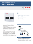
Zone Indicator
1
2
3
Accessory Modules Fail ( Refer to 5.1 )
1
Keypad 1 fail (Refer to 5.1.1 )
2
Keypad 2 fail (Refer to 5.1.2 )
3
DX 3010 Fail (Refer to 5.1.3 )
4
B420/DX 4020 /-G Fail (Refer to 5.1.4 )
Power Faults (Refer to 5.2 )
1
AC Fault (Refer to 5.2.1 )
2
Fault Battery (Refer to 5.2.2 )
3
Aux Power Supply Fault (Refer to 5.2.3 )
4
Bosch Option Bus Power Fault (Refer to 5.2.4 )
5
RF Power Fault (Refer to 5.2.5 )
Warning Device Failure List (Refer to 5.3 )
1
Warning Device 1 Disconnected (Refer to 5.3.1 )
2
Warning Device 1 Short (Refer to 5.3.2 )
3
Warning Device 2 Disconnected (Refer to 5.3.3 )
4
Warning Device 2 Short (Refer to 5.3.4 )
4
Telephone Line Fail (Refer to 5.4 )
5
Date and Time Fail (Refer to 5.5 )
6
Communications failure (Refer to 5.6 )
7
F.01U.241.127 | V2 | 2011.09
1
Communication Failure 1 (Refer to 5.6.1 )
2
Communication Failure 2 (Refer to 5.6.2 )
3
Communication Failure 3 (Refer to 5.6.3 )
4
Communication Failure 4 (Refer to 5.6.4 )
Tamper (Refer to 5.7 )
1
On board Tamper (Refer to 5.7.1 )
2
Keypad 1 Tamper (Refer to 5.7.2 )
3
Keypad 2 Tamper (Refer to 5.7.3 )
4
Keypad Lock out (Refer to 5.7.4 )
5
Sensor Tamper (Refer to 5.7.5 ) (Zone 1-8)
Installation Manual Robert Bosch Engineering and Business Solutions Limited
AMAX panel 2000 / AMAX panel 2000 EN
6
8
5.1
Fault and Tamper Description | en
29
Tamper Zone (Refer to 5.7.6 ) (Zone 1-8)
External Fault (Refer to 5.8 )
Accessory Modules Fail
The zone indicator 1 lights to indicate external module fail.Enter [1] to step to external
modules fail list for more information.
5.1.1
Keypad 1 fail
Condition:
1.
Keypad fail is reported at any time when communication fails between panel and address
1 keypad.
Restore:
Communication between panel and keypads comes back to normal and fault is reset.
Supervise:
1.
Report the keypad fault to the configured destination programmed on location 140.
2.
Flash FAULT indicator on the other keypad in normal operation (refer to the detailed
description in chapter keypad indicators).
3.
Keypad missing communication with the panel performance as below:
-Stop detection on the keypad button
-Flash FAULT indicator
-The disconnected keypad do not sound FAULT beeping per minute
4.
When the keypad fault is restored, send the restore report to the configured destinations
of the control panel system. The FAULT indicator is turned off when there is no other
system fault.
5.1.2
Keypad 2 fail
Condition:
1.
Keypad fail is reported at any time communication fails between the panel and address 2
keypad.
NOTICE!
Keypad 2 fail is only reported when Keypad 2 was connected during powering up the system!
Restore:
Communication between panel and keypads comes back to normal and fault is reset.
Supervise:
1.
Report the keypad fault to the configured destination programmed on location 140.
2.
Slow flash the FAULT indicator on the other keypad in normal operation (refer to the
detailed description in chapter keypad indicators).
3.
Keypad missing communication with the panel performance as below:
-Stop detection on the keypad button
-Flash FAULT indicator
-The disconnected keypad does not sound FAULT beeping per min
4.
When the keypad fault is restored, send the restore report to the configured destinations
of the control panel system. The FAULT indicator is turned off when there is no other
system fault.
Robert Bosch Engineering and Business Solutions Limited Installation Manual
F.01U.241.127 | V2 | 2011.09
30
en | Fault and Tamper Description
5.1.3
AMAX panel 2000 / AMAX panel 2000 EN
DX3010 Fail
The fault is registered when the DX3010 fails. The fault is reset when the DX3010 is restored.
Condition:
No communication with DX3010 if DX3010 is programmed.
Restore:
Communicaiton with DX3010 is normal and fault is reset.
Supervise:
1.
Report the DX3010 fault to configured destination on location 140 when the fault is
detected.
2.
Slow flash the FAULT indicator (refer to the detailed description in chapter keypad
indicators)
3.
When the fault is restored, send the restored report to the configured destinations. The
FAULT indicator is turned off when there is no other system fault.
5.1.4
B420/DX4020/ITS-DX4020G Fail
The fault is registered when the B420/DX4020/ITS-DX4020G fails. The fault is reset when the
B420/DX4020/ITS-DX4020G is restored.
Condition:
No communication with the DX4020/ITS-DX4020G if DX4020/ITS-DX4020G is programmed.
Restore:
Communication with DX4020/ITS-DX4020G is normal and fault is reset.
Supervise:
1.
Report the DX4020/ITS-DX4020G fault to configured destination on location 140 when
the fault is detected.
2.
Slow flash the FAULT indicator (refer to the detailed description in chapter keypad
indicators)
3.
When the fault is restored, send the restored report to the configured destinations. The
FAULT indicator is turned off when there is no other system fault.
5.2
Power Faults
The zone indicator 2 lights to indicate Power Faults. Enter [2] to step to Power Faults list for
more information.
5.2.1
AC Failure
Condition:
1.
18V AC supply deficiency to panel caused by tansformer .
2.
220V power supply fuze broken.
3.
220V power supply disconnected.
Restore:
AC MAINS supply is reconnected and fault is reset.
1.
2.
Monitor the voltage by MPU.
If the AC fault is not restored in 1 hour after the fault occured, report the fault to
configured destination on location 140.
3.
4.
Slow flash the FAULT indicator
As the AC supply is reconnected, the MAINS indicator is back to light (except in
Programming Mode or Code Functions Mode ).
5.
F.01U.241.127 | V2 | 2011.09
When the fault is restored, send the restored report to the configured destinations.
Installation Manual Robert Bosch Engineering and Business Solutions Limited
AMAX panel 2000 / AMAX panel 2000 EN
5.2.2
Fault and Tamper Description | en
31
Battery Failure
Condition:
1.
Battery voltage is lower than 11.8V+-1%.
2.
No battery connected.
Restore:
When Battery voltage rises to 12.5V+-1%, Dynamic Battery test is performed (time set in
Programming location 191) and fault is reset.
Supervise:
1.
The system performs a Dynamic Battery Test every time (set in location 191) and every
time the system is armed or reset.
2.
Report the low battery to the configured destination programmed on location 140.
3.
Slow flash the FAULT indicator (refer the detailed description in chapter keypad
indicators)
4.
When the battery is restored, send the low battery restore report to the configured
destinations of the control panel system. The FAULT indicator is turned off when there is
no other system fault.
5.2.3
AUX Power Supply Fail
Condition:
Aux Power Supply Voltage is lower than 9V+-5%.
Restore:
Voltage is raised to 12.5V+-5% and fault is reset.
Supervise:
1.
Monitor the voltage by MPU.
2.
Report the AUX power fault to the configured destination programmed on location 140.
3.
Slow flash the FAULT indicator (refer to the detailed description in chapter keypad
indicators)
4.
When the AUX power supply is restored, send the restore report to the configured
destinations of the control panel system. The FAULT indicator is turned off when there is
no other system fault.
5.2.4
Bosch Option Bus Power Supply Fail
Condition:
Bosch option bus power supply Voltage is lower than 9V+-5%.
Restore:
Voltage is raised to 12.5V+-5% and fault is reset.
Supervise:
1.
Monitor the voltage by MPU.
2.
Report the AUX power fault to the configured destination programmed on location 140.
3.
Slow flash the FAULT indicator (refer to the detailed description in chapter keypad
indicators)
4.
When the AUX power supply is restored, send the restore report to the configured
destinations of the control panel system. The FAULT indicator is turned off when there is
no other system fault.
5.2.5
RF Power Supply Fail
RF power supply fail is registered when the RF Power output fails. After the RF power output
is restored, the control panel sends a trouble restore report.
Condition:
Voltage is lower than 4V+-5%.
Robert Bosch Engineering and Business Solutions Limited Installation Manual
F.01U.241.127 | V2 | 2011.09
32
en | Fault and Tamper Description
AMAX panel 2000 / AMAX panel 2000 EN
Restore:
Voltage is raised to 5.5V+-5% and fault is reset.
Supervise:
1.
Monitor the voltage by MPU.
2.
Report the RF power fault to the configured destination programmed on location 140.
3.
Slow flash the FAULT indicator (refer to the detailed description in chapter keypad
indicators)
4.
When the RF power supply is restored, send the restore report to the configured
destinations of the control panel system. The FAULT indicator is turned off when there is
no other system fault.
5.3
Warning Device Failure
The zone indicator 3 lights to indicate Warning Device Failure. Enter [3] to step to external
modules fail list for more information.
5.3.1
Warning Device 1 Disconnected
Condition:
Warning Device is disconnected.
Restore:
Warning Device is connected and fault is reset.
Supervise:
1.
Monitor the voltage by MPU.
2.
Report the siren fault to the configured destination programmed on location 140
3.
Slow flash the FAULT indicator (refer to the detailed description in chapter keypad
indicators)
4.
When the siren is restored, send the restore report to the configured destinations of the
control panel system. The FAULT indicator is turned off when there is no other system
fault.
5.3.2
Warning Device 1 Short
Condition:
Warning Device output is shorted.
Restore:
Warning Device output short is removed and fault is reset.
Supervise:
1.
Monitor the voltage by MPU.
2.
Report the siren fault to the configured destination programmed on location 140.
3.
Slow flash the FAULT indicator (refer to the detailed description in chapter keypad
indicators)
4.
When the siren is restored, send the restore report to the configured destinations of the
control panel system. The FAULT indicator is turned off when there is no other system
fault.
5.3.3
Warning Device 2 Disconnected
Condition:
Warning Device is disconnected.
Restore:
Supervise:
1.
Monitor the voltage by MPU.
2.
Report the siren fault to the configured destination programmed on location 140.
F.01U.241.127 | V2 | 2011.09
Installation Manual Robert Bosch Engineering and Business Solutions Limited
AMAX panel 2000 / AMAX panel 2000 EN
3.
Fault and Tamper Description | en
33
Slow flash the FAULT indicator (refer to the detailed description in chapter keypad
indicators)
4.
When the siren is restored, send the restore report to the configured destinations of the
control panel system.
The FAULT indicator is turned off when there is no other system fault.
5.3.4
Warning Device 2 Short
Condition:
Warning Device output is shorted.
Restore:
Warning Device output short is removed and fault is reset.
Supervise:
1.
Monitor the voltage by MPU.
2.
Report the siren fault to the configured destination programmed on location 140.
3.
Slow flash the FAULT indicator (refer to the detailed description in chapter keypad
indicators)
4.
When the siren is restored, send the restore report to the configured destinations of the
control panel system.
The FAULT indicator is turned off when there is no other system fault.
5.4
Telephone Line Fault
Condition:
Telephone line is broken or disconnected.
Restore:
Telephone line is restored or connected and fault is reset.
Supervise:
1.
Monitor the telephone line by MPU all the time when the telephone is idle.
2.
As the fault is detected, slow flash the FAULT indicator (refer the detailed description in
chapter keypad indicators).
3.
Once the fault is reset, the FAULT indicator is turned off when there is no other system
fault.
5.5
Date and Time Fail
Condition:
Date and time is not set after the system is powered on.
Restore:
Date and time is programmed and the fault is reset. Refer to Section 3.1.1 Setting date and
time for more information.
Supervise:
1.
No report on the date and time fault.
2.
Slow flash the FAULT indicator (refer the detailed description in chapter keypad
indicators)
3.
No report to the control panel system when the fault is reset and the date and time
setting is recorded in non-volatile memory.
The FAULT indicator is turned off when there is no other system fault.
Robert Bosch Engineering and Business Solutions Limited Installation Manual
F.01U.241.127 | V2 | 2011.09
34
en | Fault and Tamper Description
5.6
AMAX panel 2000 / AMAX panel 2000 EN
Communication Failure
The zone indicator 6 lights to indicate Communication Failure. Enter [6] to step to
Communication failure list for more information.
5.6.1
Communication Failure 1
Condition:
Panel can not send the report to the Destination 1 after 4 attempts.
Restore:
The fault is reset when the first kissoff tone is received.
Supervise:
1.
Report the fault to configured destination on location 140 when the fault is detected.
2.
Slow flash the FAULT indicator (refer the detailed description in chapter keypad
indicators).
3.
When the fault is restored, send the restored report to the configured destinations. The
FAULT indicator is turned off when there is no other system fault.
5.6.2
Communication Failure 2
Condition:
Panel can not send the report to the Destination 2 after 4 attempts.
Restore:
The fault is reset when the first kissoff tone is received.
Supervise:
1.
2.
Report the fault to configured destination on location 140 when the fault is detected.
Slow flash the FAULT indicator (refer the detailed description in chapter keypad
indicators).
3.
When the fault is restored, send the restored report to the configured destinations. The
FAULT indicator is turned off when there is no other system fault.
5.6.3
Communication Failure 3
Condition:
Panel can not send the report to the Destination 3 after 4 attempts.
Restore:
The fault is reset when the first kissoff tone is received.
Supervise:
1.
2.
Report the fault to configured destination on location 140 when the fault is detected.
Slow flash the FAULT indicator (refer the detailed description in chapter keypad
indicators).
3.
When the fault is restored, send the restored report to the configured destinations. The
FAULT indicator is turned off when there is no other system fault.
5.6.4
Communication Failure 4
Condition:
Panel can not send the report to the Destination 4 after 4 attempts.
Restore:
The fault is reset when the first kissoff tone is received.
Supervise:
1.
2.
Report the fault to configured destination on location 140 when the fault is detected.
Slow flash the FAULT indicator (refer the detailed description in chapter keypad
indicators).
3.
When the fault is restored, send the restored report to the configured destinations. The
FAULT indicator is turned off when there is no other system fault.
F.01U.241.127 | V2 | 2011.09
Installation Manual Robert Bosch Engineering and Business Solutions Limited
AMAX panel 2000 / AMAX panel 2000 EN
5.7
Fault and Tamper Description | en
35
Tamper Condition
The zone indicator 7 lights to indicate Tamper conditions. Enter [7] to step to Tamper
conditions list for more information.
5.7.1
On Board Tamper
Onboard Tamper Condition is registered when the Onboard Tamper input (P8) is open.
Condition:
Onboard Panel Tamper input P8 is open.
Restore:
The Tamper condition is reset when the Input is shorted.
Supervise:
1.
Report the Tamper condition to configured destination on Location 140 when the
Tamper Condition is detected.
2.
Slow flash the FAULT indicator (refer the detailed description in chapter keypad
indicators).
3.
When the Tamper Condition is restored, send the restored report to the configured
destinations.
5.7.2
Keypad 1 Tamper
Condition:
Keypad 1 is opened and the Tamper contact is triggered.
Restore:
The Tamper condition is reset when the Keypad is closed.
Supervise:
1.
Report the Tamper condition to configured destination on Location 140 when the
Tamper Condition is detected.
2.
Slow flash the FAULT indicator (refer the detailed description in chapter keypad
indicators).
3.
When the Tamper Condition is restored, send the restored report to the configured
destinations.
The FAULT indicator is turned off when there is no other system fault.
5.7.3
Keypad 2 Tamper
Condition:
Keypad 2is opened and the Tamper contact is triggered.
Restore:
The Tamper condition is reset when the Keypad is closed.
Supervise:
1.
Report the Tamper condition to configured destination on Location 140 when the
Tamper Condition is detected.
2.
Slow flash the FAULT indicator (refer the detailed description in chapter keypad
indicators).
3.
When the Tamper Condition is restored, send the restored report to the configured
destinations.
The FAULT indicator is turned off when there is no other system fault.
5.7.4
Keypad lock out
Condition:
Invalid code is entered more times than allowed by the code retry attempts (programmed in
location 179)
Restore:
Robert Bosch Engineering and Business Solutions Limited Installation Manual
F.01U.241.127 | V2 | 2011.09
36
en | Fault and Tamper Description
AMAX panel 2000 / AMAX panel 2000 EN
Keypad lock out is reset when the Keypad lockout time (3min) is expired.
Supervise:
1.
Report the Keypad lock out to configured destination on Location 140 when the Keypad
lock out is detected.
5.7.5
2.
Slow flash the FAULT indicator.
3.
The FAULT indicator is turned off when there is no other system fault.
Sensor Tamper
Condition:
Tamper contact is triggered (Zone is programmed as Dual End of Line)
Restore:
Tamper contact is restored and Tamper condition is reset.
Supervise:
1.
Report the Sensor Tamper to configured destination on Location 140 when the Keypad
lock out is detected.
2.
Slow flash the FAULT indicator (refer the detailed description in chapter keypad
indicators).
3.
When the Sensor Tamper is restored, send the restored report to the configured
destinations. The FAULT indicator is turned off when there is no other system fault.
Sensor Tamper Zone Indication
The zone indicator 5 lights to indicate Sensor Tamper conditions.
Enter [5] to step to Zone Indicator list to identify the Zone where the Sensor Tamper comes
from.
1=Zone 1 2=Zone 2 3=Zone 3 4=Zone 4 5=Zone 5 6=Zone 6 7=Zone 7 8=Zone 8
5.7.6
Zone Tamper
Condition:
Tamper contact (direct connected to the Zone) is triggered (Zone type = Tamper)
Restore:
Tamper contact is restored and Tamper condition is reset.
Supervise:
1.
Report the Tamper condition to configured destination on Location 140 when the
Tamper condition is detected.
2.
Slow flash the FAULT indicator (refer the detailed description in chapter keypad
indicators).
3.
When the Tamper is restored, send the restored report to the configured destinations.
The FAULT indicator is turned off when there is no other system fault.
Zone Tamper Zone Indication
The zone indicator 6 lights to indicate Tamper conditions.
Enter [6] to step to Zone Indicator list to identify the Tamper Zone.
1=Zone 1 2=Zone 2 3=Zone 3 4=Zone 4 5=Zone 5 6=Zone 6 7=Zone 7 8=Zone 8
5.8
External Fault
Condition:
Fault contact (direct connected to the Zone) is triggered (Zone type = External Fault)
Restore:
Fault contact is restored and Fault condition is reset.
F.01U.241.127 | V2 | 2011.09
Installation Manual Robert Bosch Engineering and Business Solutions Limited
AMAX panel 2000 / AMAX panel 2000 EN
Fault and Tamper Description | en
37
Supervise:
1.
Report the Fault condition to configured destination on Location 140 when the Fault
condition is detected.
2.
Slow flash the FAULT indicator (refer the detailed description in chapter keypad
indicators).
3.
When the Fault is restored, send the restored report to the configured destinations. The
FAULT indicator is turned off when there is no other system fault.
External Fault Zone
The zone indicator 8 lights to indicate External Fault conditions.
Enter [8] to step to Zone Indicator list to identify the zone where the fault input is connected.
1=Zone 1 2=Zone 2 3=Zone 3 4=Zone 4 5=Zone 5 6=Zone 6 7=Zone 7 8=Zone 8
Robert Bosch Engineering and Business Solutions Limited Installation Manual
F.01U.241.127 | V2 | 2011.09
38
6
en | System Functions
AMAX panel 2000 / AMAX panel 2000 EN
System Functions
User
Install
Code
er
Function
Description
Code
•
•
0
#
Duress alarm (Refer to 6.1 )
•
•
1
#
Siren test (Refer to 6.2 )
•
•
2
#
Fault and Tamper analysis (Refer to 6.3 )
•
•
3
#
View date and time (Refer to 6.4 )
•
•
4
#
Walk test (Refer to 6.5 )
•
•
5
#
Event memory recall (Refer to 6.6 )
•
•
6
#
Reset panel/clear siren (Refer to 6.7 )
•
•
7
#
Initiate a modem call (Refer to 6.8 )
•
•
8
#
Send Test report (Refer to 6.9 )
•
•
9
#
Bypass (inhibit) (Refer to 6.10 )
•
•
96
#
Show Zone type (Refer to 6.11 )
•
97
#
Bypass all faults (Refer to 6.12 )
•
98
#
Enable=# / Disable=* installer code user's access (Refer to
*
6.13 )
•
•
99
#
Change individual code (Refer to 6.14 )
•
955
#
Change/View date and time (Refer to 6.15 )
•
956
#
Add/delete a level 2 user (Refer to 6.16 )
•
956
#
Add/delete Remote Radio User Codes (Refer to 6.17 )
•
957
#
Change domestic phone numbers (Refer to 6.18 )
•
958
#
Enter Programming Mode (Refer to 6.19 )
•
959
#
Exits from installer’s programming mode without saving
the programmed data. (Refer to 6.20 )
•
960
#
Exits from installer’s programming mode with saving the
programmed data. (Refer to 6.21 )
•
961
#
Resets the control panel to factory defaults. (Refer to
6.22 )
•
962
#
Copies the control panel memory to the programming key.
(Refer to 6.23 )
•
963
#
•
999
#
Copies the programming key data to the control panel
memory. (Refer to 6.24 )
Displays the software version number or control panel
type. (Refer to 6.25 )
Default Pads on PCB
Default the control panel with the hardware (Refer to
6.26 )
6.1
Duress alarm
This function allows code holders to perform a keypad Duress Alarm.
A Keypad Duress Alarm is used as a silent holdup alarm when 0 is added to the end of a valid
Code used to disarm the system.
F.01U.241.127 | V2 | 2011.09
Installation Manual Robert Bosch Engineering and Business Solutions Limited
AMAX panel 2000 / AMAX panel 2000 EN
System Functions | en
39
A Duress Alarm is useful only if your system reports to a monitoring station, because domestic
reporting format cannot define the type of alarm that occurred.
6.2
Siren Test
This function allows code holders to test Sirens.
Enter your Code + [1] and press [#] two beeps sound and siren's are activated for a 1~2 sec
burst. No other sounding device operates during this mode. This function can only be
operated as:
6.3
1.
Disarm
2.
No siren output is running.
Fault and Tamper Analysis Mode
This function allows code holders to identify detailed Faults and Tamper conditions.
There are a number of system faults that can be detected by the control panel. When any of
these faults are present, the FAULT indicator flashes and the keypad beeps once per minute.
Refer to Section 5 Fault and Tamper Description, page 28 for more information on each fault
type.
To determine the type of fault:
1.
Enter your Code + [2] and press [#] two beeps sound
The STAY, AWAY, and FAULT indicators flash.
One or more zone indicators (1 - 8) light to indicate the type of fault that occurred.
NOTICE!
It only can be operated in Disarm Mode.
6.4
View date and time
This function allows user code holder to view the date and time
1.
Enter your code +[3] and press [#]. Two beeps sound, the STAY and AWAY indicators
flash and date + time is shown in the format YYMMDD HHMM.
2.
If operation is not carried out within 240 seconds after entering the date and time setting
interface, the system will automatically exit from the setting.
6.5
Walk Test Mode
This function allows code holders to test detection devices to ensure they are functioning
correctly. Before activating Walk Test Mode, bypass any zones that are not required for
testing.
To enter Walk Test Mode:
1.
Enter your Code + [4] and press [#] .
Two beeps sound and the STAY and AWAY indicators flash. The keypad beeps once per
sec when Walk Test Mode is active.
2.
Unseal and seal the zones to be tested.
The keypad sounds one second beep and the siren sounds one beep each time when a
zone status is changed.
3.
Press [#] to exit from this function.
Two beeps sound and the STAY and AWAY indicators are extinguished. The system
returns to the disarmed state.
Robert Bosch Engineering and Business Solutions Limited Installation Manual
F.01U.241.127 | V2 | 2011.09
40
en | System Functions
4.
AMAX panel 2000 / AMAX panel 2000 EN
If the operation is not carried out within 240 seconds after entering the walk test mode,
the system will automatically exit from the setting.
6.6
Event Memory Recall Mode
This function allows you to play back the last 254 system events that occurred. Event Memory
Recall Mode reports all alarms and each arming or disarming of the system and helps with
troubleshooting system faults. The events are shown using the keypad indicators.
Defined events are shown using keypad indicators, refer to Section 8.3 System Event Memory
Recall, page 67 for more information.
To enter Event Memory Recall Mode:
Enter your Code + [5] and press # two beeps sound.
Two beeps sound. The events are played back by the keypad indicators in reverse
chronological order.
Example
If the events occurred in the following order:
Sequence
Event
1
System armed in AWAY Mode
2
Alarm in Zone 3
3
Alarm in Zone 4
4
System disarmed
Table 6.1
Event Sequence
The alarm memory is played back in this order:
Sequence
Indication
Event
1
All indicators off
System disarmed
2
Zone 4 and away indicators light
Alarm in Zone 4
3
Zone 3and away indicators light
Alarm in Zone 3
4
AWAY indicator lights
System armed in AWAY Mode
Table 6.2
Event Memory Playback
Sequnece indication Event
1.
All indicators off System disarmed
2.
Zone 4 and AWAY indicators light Alarm in Zone 4
3.
Zone 3 and AWAY indicators light Alarm in Zone 3
4.
AWAY indicator lights System armed in AWAY Mode
Each event is indicated by a beep and a lit indicator. Resetting a disarmed 24-Hour Alarm is
indicated by a beep only.
After the last event, two beeps sound to indicate the end of the playback. You can stop the
replay at any time by pressing [#] .
If the system is armed in STAY Mode, the STAY indicator shows the event memory playback.If
the control panel is powered down, the memory of all events is saved.
6.7
Reset panel/clear siren
This function allows code holders to reset all Alarms Faults and Tamper conditions.
Enter your code + [6] and press #.
F.01U.241.127 | V2 | 2011.09
Installation Manual Robert Bosch Engineering and Business Solutions Limited
AMAX panel 2000 / AMAX panel 2000 EN
System Functions | en
41
NOTICE!
You can only reset Alarms Faults or Tamper conditions, when the related contact or function is
idle.
6.8
Initiate a Modem Call
Enter your Code + [7] and press # two beeps sound and the control panel dials the callback
telephone number programmed in Location 154 – 169 in an attempt to connect to the
installer’s remote computer.
The remote computer must be running the remote programming software and must be set to
Waiting for an Incoming Call. If no callback telephone number is programmed, entering code
+[7] has no effect.
6.9
Send Test Report
This function allows code holder to send a test report to a Central Monitoring Station (CMS).
1.
Enter your code + [8] and press #.
Two beeps sound and a test report is sent.
6.10
Bypass Zones
This function allows code holders to manually disable one or more zones before arming the
system in AWAY Mode or STAY Mode. When a zone is bypassed, access is allowed into that
zone when the system is armed without activating an alarm.
The zone should be programmed as bypass zone enable. If the zone is not programmed as
bypass zone, then it cannot be bypassed manually as bypass zone.
For example, you might want to isolate a zone before arming the system because a zone
passive infrared (PIR) detector is activating false alarms or because you need to leave a pet
inside a particular zone while you are away.
Key-switch zone can’t be bypassed.
The non-used zone can’t be bypassed.
Alarm Zones isolating:
1.
Zones that have been bypassed will report to CMS at once.
2.
When the zone bypassed is restored, it will send the restore report to CMS immediately.
3.
When the system is disarmed again after arming, the bypassed zones will be restored. It
will send the bypassed restore report to CMS.
Bypass Steps:
1.
Enter your Code + [3] and press [#] . the AWAY and STAY indicators flash.
2.
Enter the number of the zone to be bypassed and press [*]. Repeat Step 2 for each zone
you want to isolate.
3.
To cancel any isolated zone, enter the number of isolated zone and press [*]. Repeat
Step 3 for each zone you have bypassed.
4.
Press [#] to exit.
For example:
To manually bypass zones 1,3 and 4, press:
[Code][9][#][1][*][3][*][4] [*][#]
6.11
Show Zone Type
This function allows code holders to see the zone type
Robert Bosch Engineering and Business Solutions Limited Installation Manual
F.01U.241.127 | V2 | 2011.09
42
en | System Functions
1.
AMAX panel 2000 / AMAX panel 2000 EN
Enter your Code + [96] and press [#] .
Two beeps sound and the STAY and AWAY indicators flash.
2.
3.
Zone type for Zone 1 is shown
Press [#] to jump to Zone 2
Two beeps sound and the STAY and AWAY indicators flash.
4.
5.
6.12
Repeat this procedure to jump to the other Zones.
To exit this function press [*]
Bypass all Faults and Tamper conditions (Except zone Tamper)
This function allows code holders to bypass faults and Tamper conditions.
1.
Enter your code + [97] and press [#].
Two beeps sound.
NOTICE!
This function works only if loction 183 is 0=disabled. If location 183 is 1=enabled, Faults and
Tamper conditions are automatically overwitten.
6.13
Enable Disable installer code user’s access
This function allows user code holder to enable or disable the installer code user to access
the programming mode
1.
Enter your user code +[98] and press [#] to enable the function
Two beeps sound
2.
Enter your user code + [98] and press [*] to disable the function
Two beeps sound
6.14
Change individual code
This function allows user to change there individual codes.
1.
Enter your Code + [99] and press [#] .
Two beeps sound and the STAY and AWAY indicators flash.
2.
Enter the new code and press [#].
Two beeps sound and the STAY and AWAY indicators are extinguished.
NOTICE!
This function is terminated automatically if you do not press a button within 240 sec or if
youpress [#] . One long beep indicates that the code already exists or that an incorrect
number has been entered.
6.15
Setting date and time
This function allows the installer code holder to set or view the date and time
1.
Enter your installer code +955 and press [#]. Two beeps sound, the STAY and AWAY
indicators flash and date + time is shown in the format YYMMDD HHMM.
2.
Enter the year, month, day, hour and minute in YY, MM, DD, HH, MM format and press [#].
Use 24:00 hour format when programming the hour of the day. Beep sound and the
STAYand AWAY indicators are deactivated. If a long beep sounds, it indicates an
erroneous entry of date and time.
3.
If operation is not carried out within 240 seconds after entering the date and time
setting interface, the system will automatically exit from the setting.
Example
F.01U.241.127 | V2 | 2011.09
Installation Manual Robert Bosch Engineering and Business Solutions Limited
AMAX panel 2000 / AMAX panel 2000 EN
System Functions | en
43
To set the date and time for the 25th of December 2010 at 10:30PM, enter:
[1234] [955][#] break until time is shown [1 0 1 2 2 5 2 2 3 0][#]
6.16
Add/delete User Codes
This function allows the Installer Code holder to change or delete a User Code.
1.
Enter your Installer Code +956 and press [#] .
Two beeps sound and the STAY and AWAY indicators flash.
2.
Enter the numbr of the code (1 - 8) you want to change and press [#] .
Two beeps sound and the corresponding zone indicator lights.
3.
Enter the new code and press [#].
Two beeps sound and the STAY and AWAY indicators are extinguished.
4.
Repeat this procedure to change other User Codes.
NOTICE!
This function is terminated automatically if you do not press a button within 240 sec or if you
press [#] . One long beep indicates that the code already exists or that an incorrect number
has been entered
Example
To program User Code number 2 as 4627, enter:[1 2 3 4 ] [958] [#][2][#][4 6 2 7][#]
To delete a User Code:
1.
Enter your Installer Code + 956 and press [#] . Two beeps sound and the STAY and AWAY
indicators flash.
2.
Enter the number of the code (1 - 8) you want to change and press [#] . Two beeps sound
and the corresponding zone indicator lights.
3.
Press [*] to delete the User Code. Two beeps sound and the STAY and AWAY indicators
are extinguished.
4.
Repeat this procedure to delete other User Code.
NOTICE!
This function is terminated automatically if you do not press a button within 240 sec or if you
press [#] . One long beep indicates that the code already exists or that an incorrect number
has been entered
6.17
Add/delete Radio User Codes
This function allows the Installer Code holder to add or delete a Remote Radio User Code(if
enabeled in location 182)
To add or change a Remote Radio User Code:
1.
Enter your Installer Code +956 and press [#] . Two beeps sound and the STAY and AWAY
indicators flash.
2.
Enter the number of the code (9 - 16) you want to change and press [#] . Two beeps
sound and the corresponding zone indicator lights.
3.
Press any of the (transmit) buttons on the hand held key-fob. Two beeps sound and the
STAY and AWAY indicators are extinguished.
4.
Repeat this procedure to change other Remote Radio User Codes.
Robert Bosch Engineering and Business Solutions Limited Installation Manual
F.01U.241.127 | V2 | 2011.09
44
en | System Functions
AMAX panel 2000 / AMAX panel 2000 EN
NOTICE!
This function is terminated automatically if you do not press a button within 240 sec or if
youpress [#] . One long beep indicates that the code already exists or that an incorrect
number has been entered.
To delete a Remote Radio User Code:
1.
Enter your Installer Code + 956 and press [#] . Two beeps sound and the STAY and AWAY
indicators flash.
2.
Enter the number of the code (9 - 16) you want to change and press [#] . Two beeps
sound and the corresponding zone indicator lights.
3.
Press [*] to delete the User Code. Two beeps sound and the STAY and AWAY indicators
are extinguished.
4.
6.18
Repeat this procedure to delete other Remote Radio User Codes
Change Domestic Phone Number
When the system is set up for domestic dialing, this function allows the installer to view and
program the telephone numbers that the system calls if an alarm occurs. Refer to
Section 7.5 Domestic Dialing, page 50 for more information.
To change domestic phone number:
1.
Enter the installer Code and press [957]. Two beeps sound and the STAY and AWAY
indicators flash.
2.
Enter the phone number. Each digit appears as you enter it.
3.
Press [#] to exit from this mode.
Example
If you want to program telephone number (9672 1777, enter:[Installer CODE + 9 5 7][#][9 6 7
2 1 7 7 7][#]
You can cancel the domestic dialing function at any time. Such as you moved to other
placesand do not want the system to dial your working phone number or mobile number any
more.
To disable domestic dialing:
Enter the installer Code and press [957], then set the first number as 15.
6.19
Enter Programming Mode
This function allows installer code holders to access the programming modeEnter the installer
code + 958 and press [#] .
Two beeps sound and both the STAY and the AWAY indicators flash simultaneously to indicate
that you have into entered installer’s programming mode.
Once you enter into installer’s programming mode, you are automatially positioned at location
000.
6.20
Command 959 – Exit from installer’s programming mode
without saving the programmed data
This command exits from the installer’s programming mode.
You can exit from installer’s programming mode from any location. No data will be saved
whenthis command is performed.
Exit from Installer’s programming mode without saving the programmed data:
F.01U.241.127 | V2 | 2011.09
Installation Manual Robert Bosch Engineering and Business Solutions Limited
AMAX panel 2000 / AMAX panel 2000 EN
System Functions | en
45
Enter [9 5 9 #] under installer’s programming mode. Two beeps sound and system returns
tothe disarmed state. The STAY and AWAY indicators are deactivated
.
6.21
Command 960 – Exit from installer’s programming mode with
saving the programming data
This command exits from the installer’s programming mode.
You can exit from installer’s programming mode from any location.
Exit from installer’s programming mode:
Enter [9 6 0 #] under installer’s programming mode.Two beeps sound and system resets
aftersaving the programmed data and returns to the disarmed state. The STAY and
AWAYindicators are deactivated.
6.22
Command 961 – Reset the control panel to factory default
settings
This command resets the control panel to factory default value. Default values are listed
throughtout this guide and in Section 10 Programming sheets on Page 77.
To reset the control panel to factory defaults:
1.
Enter the installer code (the default is 1234 + 958) and press [#] to enter into installer’s
programming mode. Two beeps sound and the STAY and AWAY indicators flash on the
remote keypad to indicate you have entered into installer’s programming mode. The
keypad displays the data stored in Location 000
2.
Enter [9 6 1 #]. Two beeps and the system is reset to the factory default values.
CAUTION!
Only command [9 6 0 #] performed, the reset factory values will be saved.
6.23
Command 962 – Copy the control panel memory to the
programming key
This command copies the control panel memory to the programming key.
To copy the control panel memory to the programming key:
1.
Enter the installer code(the default is 1234 + 958)and press [#] to enter into Installer’s
Programming Mode. Two beeps sound and the STAY and AWAY indicators flash on the
keypad to indicate you have entered into the installer’s programming mode. AMAX
keypad displays the data stored in Location 000.
2.
Connect the programming key to the PROGRAMMING KEY pins at the top of the control
panel’s PCB.
3.
Enter [9 6 2 #].
Two beeps sound after the control panel memory is successfully copied to
theprogramming key. A long beep indicates that the programming key is corrupt and
must bere-programmed by input [9 6 2 #].
4.
Enter command [9 6 0 #] to exit from installer’s programming mode.
The STAY and the AWAY indicators are extinguished on the keypad to indicate that
thesystem is disarmed.
5.
Remove the programming key from the control panel.
Robert Bosch Engineering and Business Solutions Limited Installation Manual
F.01U.241.127 | V2 | 2011.09
46
en | System Functions
AMAX panel 2000 / AMAX panel 2000 EN
CAUTION!
Failing to exit from Installer’s Programming Mode before removing the programming key
cancorrupt the programming key.
6.24
Command 963 – Copy the programming key to the control
panel
This command copies data from the programming key to the control panel.
To copy the programming key to the control panel:
1.
Enter the installer code (the default is 1234 + 958) and press [#] to enter into installer’s
programming mode. Two beeps sound and the STAY and AWAY indicators flash on the
remote keypad to indicate that you have entered into Installer’s Programming Mode. The
keypad displays the data stored in Location 000.
2.
Connect the programming key to the PROGRAMMING KEY pins at the top of the control
panel’s PCB.
3.
Enter [9 6 3 #]. Two beeps after programming key data is successfully copied to the
control panel. A long beep indicates that the programming key is corrupt and must be
reprogrammed.
4.
Enter command [9 6 0 #] to exit from installer’s programming mode.
The STAY and the AWAY indicators are extinguished on the keypad to indicate that the
system is disarmed.
5.
Remove the programming key from the control panel.
CAUTION!
Failing to exit from Installer’s Programming Mode before removing the programming key
cancorrupt the programming key.
6.25
Command 999 – Display the software version number
The version structure is: Vx.xx. This command displays the panel software version.
1.
Enter [9 9 9 #] under installer’s programming mode. The keypad will display the first
number.
2.
Press [*] to display the next number.
Display example: For the version 3.17
Enter [9 9 9 #] under the programming mode.
The keypad displays 1st number 3; and press [*] to display the 2nd number 1; then press [*]
to display the 3rd number 7.
Continue to press [*] and no version number will be displayed.
Enter [9 5 9 #] or [9 6 0 #] to exit from Installer’s Programming Mode.
The STAY and the AWAY indicators are extinguished on the keypad to indicate that the system
is disarmed.
6.26
Default the control panel with the hardware
If the installer code is lost, the default pads on PCB is used to default the control panel.
1.
2.
Disconnect the AC MAINS supply and the backup battery from the control panel.
Short the default pads. The default pads is located on the right top of the PCB next to
the PROGRAMMING KEY socket.
3.
Reconnect the power supply to the control panel.
4.
If the LED on the control panel PCB fast flash, release the default pads at once.
F.01U.241.127 | V2 | 2011.09
Installation Manual Robert Bosch Engineering and Business Solutions Limited
AMAX panel 2000 / AMAX panel 2000 EN
System Functions | en
5.
The control panel is successfully defaulted to the factory settings.
6.
If the LED on control panel PCB do not fast flash, the factory default is unsuccessful.
Robert Bosch Engineering and Business Solutions Limited Installation Manual
47
F.01U.241.127 | V2 | 2011.09
48
en | System Informations 1
AMAX panel 2000 / AMAX panel 2000 EN
7
System Informations 1
7.1
Zone Processing when arming
When the system is armed, it will do the following process.
Arm precondition:
The system should be disarmed. Also the system should not be in programming mode and
walk test mode.
For arming the panel by keypad, force armed conditions are applied:
It can be armed with some zones unsealed when force arm is enabled for these zones, and
they are represented by slow flash zone indicators.
When the force arm of a zone is disabled, the zone must be in sealed status for arming the
panel.
Arm Performance:
At the end of exit delay time, send the report to the configured destinations of the control
panel by setting location 138 or location 139 to 1.
It will not arm until the exit time is up. During the exit time, if the users disarmed the system,
then no report is sent.AWAY or STAY indicators are lit to indicate the ARM status.
Send the Battery Low report to the configured destinations of the control panel system if it
occurred by the setting of location 140.
NOTICE!
Single button arming in STAY Mode reports as User Code number 18.
Record the event in history.
AWAY ARM will monitor all zones except bypassed zones. STAY ARM will only monitor the
unsealed non interior zones.
Refer to Section 8.1.2 Zone programming, page 57 for different processes with different zone
types.
7.2
Zone Processing when disarming
Disarm precondition:
The system is armed.
Disarm performance:
Send the report to the configured destinations of the control panel system by the setting of
location 138 or location 139.
AWAY and STAY indicators are extinguished.
For zone not 24-Hour and keyswitch type, send the zone alarm/trouble restore report to the
system. Refer to Section 8.1.9 Zone Fault, page 62 for more information.
Record the event in history.
Restore the bypassed zones.
Unlock the lock out zones.24-Hour zones are always monitored regardless of arm or disarm if
it is not bypassed.
Refer to Section 8.1.2 Zone programming, page 57 for different processes with different zone
types.
7.3
Alarm processing
Alarm precondition:
F.01U.241.127 | V2 | 2011.09
Installation Manual Robert Bosch Engineering and Business Solutions Limited
AMAX panel 2000 / AMAX panel 2000 EN
System Informations 1 | en
49
Anytime the 24-Hour zone is violated.
Anytime the tamper is violated.
Keypad alarm operation.
When system is armed and the armed zone, which is not bypassed, is violated.
After the entry delay time runs out, if the system has not been disarmed and the zone has
been violated, an alarm occurred.
Alarm performance:
Send the report to the configured destinations of the control panel system.
Flashing the violated zone indicators to indicate the ALARM status.
Activate the related output according to the output configuration.
Activate the keypad buzzer follow the output status by setting Location 370.
Record the event in history.
7.4
Software
You can program or control the AMAX Panel 2000 / AMAX Panel 2000 EN remotely using a PC
and remote programming software. This software allows you to change your customer’s
control panel without leaving your office.
7.4.1
Remote Connect
The remote connect feature allows you to establish a connection through the telephone
network from your computer to the AMAX Panel 2000 / AMAX Panel 2000 EN. This software
allows you to offer faster service to your clients.
7.4.2
Remote Connect with Customer Control
If you want to configure the control panel to establish a remote connection, it is possible only
when the client initiates it through the remote keypad. Program the following information:
–
Program the Call Back Telephone Number in Location 154 - 169 .
–
Start using remote program in Location 153.
The control panel is now set ready for the client to control and establish a remote connection.
To dial the remote computer:
Enter your code + [7] and press [#].
When the command operates, the control panel calls the remote computer telephone with the
remote control software open and is set to Waiting for an Incoming Call.
After uploading /downloading the data, the control panel exits from the remote program and
returns to the disarmed state.
7.4.3
Remote Connect with Callback Verification
The control panel receives the call. As the ring count set in Location 152 is reached, it picks
up the call and attempts to establish data connection with the remote computer.
NOTICE!
If the connection cannot be established, the control panel regards it as a remote arming
command and accepts it.
The control panel hangs up the telephone.
The control panel initiates a callback.
The remote computer is now operating remote programming software and is set to Waiting
for an Incoming Call.
After uploading /downloading the data, the control panel exits from callback and returns to
the disarmed state.
Robert Bosch Engineering and Business Solutions Limited Installation Manual
F.01U.241.127 | V2 | 2011.09
50
en | System Informations 1
AMAX panel 2000 / AMAX panel 2000 EN
To program the control panel for remote connection with callback verification:
7.4.4
1.
Program the Call Back Telephone Number in Location 154 – 169 .
2.
Start using remote program in Location 153.
Remotely Arm/Disarm System by Programming Softwares
Programming softwares can be used to arm/disarm system and User Code 20 is used to send
the arming/disarming reports.
7.5
Domestic Dialing
The domestic dialing telephone numbers are stored in Location 120 – 135, which can store up
to 16 digits.
7.5.1
Domestic Dialing Function
Only one dialing telephone number will be supported.
When the control panel is activated into zone tamper/ zone alarm, it dials the programmed
telephone number.
All alarm events only need one report/acknowledgement.
The transmission sequence is repeated until the control panel receives an acknowledgement
tone.
The control panel automatically hangs up after 45 seconds if it cannot dectect the
acknowledgement tone. And redial later.
The user presses [#] between two acknowledegement tones to confirm the alarming.
The acknowledgement tone is the DTMF signal sent by the remote user with the [#] .
If the control panel got the [#] acknowledgement from the user, it will send 2 seconds long
beep as acknowledge tone and hang up the line.
7.6
Reporting Formats
7.6.1
Transmission Formats
The AMAX Panel 2000 / AMAX Panel 2000 EN provides two kinds of transmission formats,
Contact ID and CFSK format, for its dialing and communication features. Program the
transmission format for Receiver 1, 2, 3 and 4 separately in Location 023, Location 053,
Location 083 and Location 113(refer to Section 7.7.4 Receiver 1 - 4 Transmission Format,
page 53).The control panel is set at the factory to report in the Contact ID Format.
7.6.2
Contact ID Format
Contact ID Format can identify hundreds of zones by their unique codes. This format provides
a single-digit Event Qualifier and a three-digit Event Code that quickly identifies the reported
condition.
In general, Contact ID Format is very simple because most of the Event Codes and Point ID
Codes are predefined. The base station software usually can identify an alarmed zone by its
Point ID Code and usually pays little attention to the Event Code.
Contact ID Message Format
ACCT MT Q EEE GG CCC S
ACCT = Subscriber ID
MT = Message type, H
Q = Event Qualifier
1= New event or Opening
3= New restore or Closing
6= Previously reported off-normal event
F.01U.241.127 | V2 | 2011.09
Installation Manual Robert Bosch Engineering and Business Solutions Limited
AMAX panel 2000 / AMAX panel 2000 EN
System Informations 1 | en
51
EEE = Event Code
GG = Group Number (always 0)
CCC = Zone/ Contact ID, 000 is for no zone/ID message
S = Checksum digit
Note: Any 0 values must be sent as an 0x0A.
Contact ID Report Data:
7.6.3
CFSK Format
The CFSK communication format is a protocol based on the standard Bell 103 FSK (Frequency
Shift Keying) modulation, as detailed by the SIA (Security Industry Associaton) “Digit
Communications Standard” November 1991.
CFSK Message Format(6/2)
B AAAAAA TE S
B = Begin ( 1 byte, always 04 )
AAAAAA= Subscriber ID (3 bytes)
T= Type of Event Code ( 1 byte)
E= Event/User/ Zone number (1 byte)
S= Checksum digit (1 byte)
Formular S = Sum of message bytes & 0xFF
Remark:
7.7
Dialer Information
This section outlines the programming information required for the AMAX Panel 200 / AMAX
Panel 2000 EN when communicating with a base station receiver. These parameters specify
the telephone numbers/IP address to be called, transmission formats and internet
communication options.
The control panel can report event information from four on-board dialers. The dialers report
to Receiver 1 to Receiver 4 by programming. You can program each dialer with 4 separate
telephone numbers/IP addresses and ports, reporting format type and subscriber ID number,
and internet communication options if necessary.
Example
You can set up Dialer 1 to report to receiver 1 in CFSK Format and set up Dialer 2, Dialer 3 and
Dialer 4 to report to a base station receiver in Contact ID Format only if Dialer 1 is
unsuccessful.
To program a telephone number:
Each location in the telephone numbers stores one digit of the telephone number.
Insert a 15 at the end of a telephone number to indicate to the dialer that the end of the
telephone number is reached. The dialing sequence is terminated when a 15 appears.
Example
To program the telephone number 9672 1055 as the Telephone Number for Receiver 1,
program the following sequence into Location 000 - 016:
[9 6 7 2 1 0 5 5 15 x x x x x x x x]x stands for any digit.To enter a 4-sec pause in the
dialing sequence, program a 13. A pause might be necessary when the dialer communicates
through an old (slower) telephone exchange or when a PABX system is in place.
Example
To program the number 02 pause 9672 1055, enter:
[0 2 13 9 6 7 2 1 0 5 5 15 x x x x x].
Table 7.1 shows how to program the numbers, keys, and functions for a telephone number.
Robert Bosch Engineering and Business Solutions Limited Installation Manual
F.01U.241.127 | V2 | 2011.09
52
en | System Informations 1
AMAX panel 2000 / AMAX panel 2000 EN
Digit Required
Number to Program
Digit Required
Number to Program
0
0
8
8
1
1
9
9
2
2
*
11
3
3
#
12
4
4
4 sec pause
13
5
5
Terminal
15
6
6
7
7
Table 7.1
Dialing Digits
To program the IP Address and port:
Use no punctuation in IP address. If any unit of IP address is less than 3 digits, use 0 to fulfill
the data in the higher bits. The remaining 5 digits will program the port. Port number ranges
from 0-65535. Any port is less than 5 digits, use 0 to fulfill the data.
Example
To program the IP Address 10.16.1.222:80 as the IP
Address of Receiver 1, enter the following sequence into Location 000 - 016:[0 1 0 0 1 6 0
0 1 2 2 2 0 0 0 8 0]
NOTICE!
Programming option anti-replay, acknowledge wait time and pulse interval time are only used
in Bosch network format.
7.7.1
Telephone number for Receiver 1 - 4/IP Address and Port
(Refer to Section 10.1.1 Receiver Parameters, page 77). When the corresponding data format
for above programming address is a network communication format, it is explained as an IP
Address and Port. For a non network format, it is explained as telephone number.
When the control panel transmits a report, it dials the telephone number/IP Address to
contact the monitoring station. If the call is successful, the relevant information is transmitted
and the dialer returns to Standby Mode.
Contact your monitoring station for the correct telephone number/IP Address before you
program these locations.
7.7.2
Other Network Programming Option
(Refer to Section 10.1.1 Receiver Parameters, page 77). When the control panel tansmits a
report in network , the following options should be programmed other than the IP Address
and port:
Anti-Replay:
Anti-replay prevents unauthorized messages from being sent to the CMS and being recognized
as originating from the control panel.
Contact your central monitoring station for the correct setting.
Acknowledge Wait Time
When no callback from the receiver after the acknowledge time is reached, the control panel
takes it as an unsuccessful communication and makes another attempt. The time ranges from
5 to 99 sec.
Contact your central monitoring station for the correct setting.
Pulse Interval Time
F.01U.241.127 | V2 | 2011.09
Installation Manual Robert Bosch Engineering and Business Solutions Limited
AMAX panel 2000 / AMAX panel 2000 EN
System Informations 1 | en
53
The pulse is used for both panel and remote receiver to know whether the network
connection is good or not. Each time when a pulse is due, the control panel will send a pulse
message. The pulse time range is from 1 to 999 minutes. For time less than 3 digits, use 0 to
fulfill.
Contact your central monitoring station for the correct setting.
7.7.3
Report Transmission Sequence
(Refer to Section 10.2.1 Report Options, page 78 and Section 10.4 Zone Programming, page 81).
If the event has disabled the report (option 0), no report is sent out. The domestic alarm is set
as configured.If the report has any destination to contact the panel (option 1, 2, 3, 4, 5, 6, 7),
It will call the related destination by related reporting format type and subscriber ID Number.
Attempt rules:
1.
Attempt times and duration
The attempt sequency is destination 1, 2, 3, 4 and domestic destination. Some disabled
destinations will be ignored.
When a new report needs to be sent out, the system will send the report based on the
report destination programming list.
For each enabled destination, the panel will retry sending the report to it till the report
has been sent to the destination, or till the report buffer overflows and the old report is
replaced by new incoming reports.
For each enabled destination, the retry interval time between two retries is 15 seconds
for the 1st retry to 4th retry, and the retry interval time between two retries is 10 minutes
for the 5th retry to 8th retry, after the 8th retry the retry interval time between two
retries is 60 minutes.
For all enabled destinations (except domestic destinations), the waiting time for next
retry would be cleared to zero as long as there is a new report.
2.
Attempt Priority
The attempt priority is destination 1, 2, 3, 4, Domestic. The disabled destinations will be
ignored.
3.
Communication Fail Fault
If the attempt times for one destination reaches 4, the system will cause the
communication fail fault for this destination.
4.
Backup Destination Process
If the destination failed for 4 attempts, the pending reports will switch between primary/
backup destinations in this group.If the report option selects 6, only one group: 1, 2, 3, 4
destinations.If the report option selects 7, there are two groups: group 1 is 1, 2
destinations. Group 2 is 3, 4 destinations.The system can save up to a maximum of 50 unreported events. If the un-reported events are more than 50, it will delete earlier events
and only save the last 50 events in the buffer to send out.
7.7.4
Receiver 1 - 4 Transmission Format
(Refer to Section 10.1.1 Receiver Parameters, page 77). You can select the transmission format
with location options to specify how to transmit the information to the base station receiver.
If Contact ID or CFSK format is selected, the information is transmitted by telephone line; if
Bosch Network is selected, then it is connected with B420/DX4020 or ITS-DX4020G GPRS.
Transmission format is defaulted as Contact ID.
Robert Bosch Engineering and Business Solutions Limited Installation Manual
F.01U.241.127 | V2 | 2011.09
54
en | System Informations 1
7.7.5
AMAX panel 2000 / AMAX panel 2000 EN
Receiver 1 - 4 Subscriber ID Number
(Refer to Section 10.1.1 Receiver Parameters, page 77). The Subscriber ID Number is
transmitted to identify the calling control panel. Enter the Subscriber ID Number in the six
locations provided for each destination. Any Subscriber ID Number is less than 6 digits, use 0
to full fill the data in the higher bits.
Example
Program Subscriber ID Number as 4729 in six locations: [0 0 4 7 2 9]
7.7.6
Call back Telephone Number
(Refer to Section 8.6.4 A-Link Plus Software, page 72 and Section 10.3.2 Remote Programming/
Control, page 79).This location stores the telephone number to call when Upload/Download is
requested or the user enters his code + 7 and presses [#] to initiate a modem call from the
control panel to establish a communication link with the remote computer. The computer
must be running A-Link Plus RPS software and must be set to Waiting for an Incoming Call.
The Call Back Telephone Number is also necessary if remote connect with callback verification
is required(refer to7.4.3 on page 49)
7.7.7
Ring Count
(Refer to Section 10.3.1 Ring Count, page 79). This location sets the number of rings before
the control panel answers an incoming call. Setting this count to an acceptable level has an
effect only if Remote Arming and the Remote Upload/Download are enabled. Programming
this location to 0 prevents the control panel from answering incoming calls regardless of any
other programmed options.
7.8
Access Codes
This section describes the access codes used to assign privileges and access functions for
User Code holders of the system. There are two types of access codes, the Installer Code and
User Codes. Each of these codes allows specific access and operation of control panel
functions.
7.8.1
Installer Code
(Refer to Section 10.6.1 Installer code # 0, page 86). The Installer Code can be up to four digits
long. When the system is in disarmed status and no active alarm, it will access to Installer’s
Programming Mode.
Installer Code functions allow the installer to execute functions when the system is disarmed.
Refer to Section 6 System Functions, page 38 for more information.Refer to
Section 3.3.1 Programming with the AMAX Keypad 2000, page 14 for more information on
system programming.
The installer code works only if its enabled by a user code holder.
7.8.2
AMAX Panel 2000 / AMAX Panel 2000 EN User Codes
(Refer to Section 10.6.2 User Codes, page 86.) The AMAX Panel 2000/AMAX Panel 2000 EN
Control Panel can have up to sixteen programmable User Codes (1 - 16) to operate the
system. You can program User Code 1-8 as keypad user codes and 9-16 as hand-held remote
radio keyfob user codes.
To remotely operate the system by hand-held keyfob, program User code 9 – 16 as remote
user code.
F.01U.241.127 | V2 | 2011.09
Installation Manual Robert Bosch Engineering and Business Solutions Limited
AMAX panel 2000 / AMAX panel 2000 EN
7.8.3
System Informations 1 | en
55
User Codes
The purpose of User Codes is to arm and disarm the system and perform system functions.
Refer to Section 6 System Functions, page 38. User Codes 1 to 8 can be one to four digits long.
Only User Codes 9 to 16 can be used as remote radio user codes. .
Use User Code 17 to send report when arming/disarming the system by key-switch.Use User
Code 18 to send report when arming the system in AWAY Mode or STAY Mode by keypad
single button.Use User Code 19 to send report when remotely arming the system by
telephone call.
Use User Code 20 to send report when remotely arming the system by A-Link Plus software.
Robert Bosch Engineering and Business Solutions Limited Installation Manual
F.01U.241.127 | V2 | 2011.09
56
en | System Informations 2
AMAX panel 2000 / AMAX panel 2000 EN
8
System Informations 2
8.1
General overview on zones
8.1.1
Zone Inputs
On-board Inputs:
There are 8 onboard hard-wired inputs for AMAX Panel 2000 / AMAX Panel 2000 EN. An
additional input is provided for enclosure tamper but does not subtract from the 8 onboard
totals.
On-board Zone Response Time:
Each on-board zone response time is:
Zone Status trigger time >= 400ms, must response
Zone Status trigger time < 300ms, no response
On board Zone EOL
1.
Single EOL: If 24-zone tamper function is not detected, each zone uses a single 2.2k ohm
EOL. The panel can detect the zone as short, normal or open.
Loop Resistance (ohm)
Min
Typ
1650
2200
Zone Status
Max
1430
triggered
2750
normal
2970
triggered
The detectors(sensors) will be connected between zone and COM terminal through EOL
series connection (open triggered) or EOL parallel connection (short triggered).
COM
Zone
Figure 8.1 Open Triggered
COM
Zone
Figure 8.2 Short Triggered
The panel sets the short/open as activate when connecting with single EOL
.The valid zone number is 1-8 for AMAX.
(2) Dual EOL: If the tamper supervision is set, we only can use the NC contact point. The EOL
status is :
Loop resistance (ohm)
Min
F.01U.241.127 | V2 | 2011.09
Type
Zone Status
Max
Installation Manual Robert Bosch Engineering and Business Solutions Limited
AMAX panel 2000 / AMAX panel 2000 EN
System Informations 2 | en
1430
tamper
1650
2200
2750
normal
2970
4400
4950
trigerred
57
Using one 2.2K resistor as EOL of the tamper zone, which works together with the zone EOL
2.2K. Refer to the drawing:
COM
1
2
Z3
BBBBB7DPSHU6ZLWFK
BBBBB=RQH6ZLWFK
Figure 8.3 Dual EOL
On -board Tamper Input
A separate input is provided for enclosure tamper (This is in addition to the 8 on-board total
inputs). The response time of the tamper input is a fixed zone response time.The tamper loop
will cause a siren alarm when the loop is open, and will be reported when the loop is open
(based the “system status report option”).When powered up, the system will wait for 60
seconds to setup the normal work.
Tamper Switch connector Input:
Close: NormalOpen: AlarmTamper Alarm process is the same as 24-Hour Alarm process
(Onboard Tamper is processed as zone number 17).
8.1.2
Zone programming
The programming information for each zone is stored in eight locations to determine how the
zone operates, the zone options, and the reporting information for the zone.
Zone Operating Information
These three locations store the Zone Type ( for example, Enter/Exit of Delay, Instant or 24Hour Zone)
Zone Options These two locations allow you to select from a number of options. Refer to
Section 8.1.4 Zone Bypass, page 61 for more information.
Zone Reporting Information
This information includes the locations for the Zone Report Code and the Zone Dialer Options.
The Zone Report Code determines whether the control panel sends Alarm Reports for the
zone. The Zone Dialer Options location enables you to specify how a zone reports to a base
station receiver.
8.1.3
Zone Types
(Refer to Section 10.4 Zone Programming, page 81).
0 and 14-15 – Zone Not Used
Robert Bosch Engineering and Business Solutions Limited Installation Manual
F.01U.241.127 | V2 | 2011.09
58
en | System Informations 2
AMAX panel 2000 / AMAX panel 2000 EN
If a zone is not used, program the zone type location to 0 or 14-15. An EOL resistor is not
required if this zone type is not used. This zone type never sounds the sirens or activates the
dialer.
1-Instant
The instant zone will perform as below:
1.
2.
Disarm: No zone triggerd a report to system
AWAY Arm:If the zone is normal, no report to the system. If the zone is triggered and
during the exit time, no alarm is reported to system. If the zone is triggered after the exit
time, an alarm report is sent to the system depending on the following situations:
(i)The zone is locked out: no report(ii)Report destination programming
3.
STAY Arm: If the zone is normal, no report is sent to the system. If the zone is triggered
after arming, an alarm report is sent to the system depending on the following situations:
(i) The zone is locked out: no report
(ii) Report destination programming
Even the instant zone is not yet restored when disarming, a zone restore report is sent to
the system. When the system is armed , if the zone is triggered and not bypassed, a fault
report is sent to the system.
2-Interior Instant
The interior instant zone will perform as below:
1.
Disarm: same as the Instant Zone disarm status
2.
AWAY Arm: same as the Instant Zone AWAY Arm status
3.
STAY Arm:The LED display. Refer to the LED display definition section. This zone will be
ignored and performed as disarm.
If an Interior Instant Zone is not restored when the system is disarmed, a Zone Restore Report
is automatically sent to the system.When the system is AWAY armed, if the zone is triggered
and not bypassed, a fault report is sent to the system.
3-Delay
The delay zone will perform as below:
1.
2.
DISARM: Same as Instant zone disarm status
AWAY Arm: If the zone is normal, no report is sent to the system. If the zone is triggered
during the exit time, an alarm is sent to the system depending on the following situations:
–
The zone is locked out: no report
–
Report destination programming
–
The zone is armed and triggered:
(i) During the entry delay time, if the system is disarmed, no alarm report sent out.
(ii) After the entry delay time, if the system is not disarmed, an alarm report sent to
system. During the entry delay time, if the zone is triggered/ normal many times, the
system will process it as one time triggered (alarm).
(iii) If the zone is triggered, the entry delay time is started, and when the entry delay
time is up, if the system didn’t disarm, the system will send alarm to the system.
(iv) If the zone is triggered during entry delay time,
and the zone is backed to nor-
mal status before the entry time is up, when the entry delay time is up, the system
will send alarm restore report to the system.
3.
STAY ARM: Same as AWAY ARM performance.
When the first delay zone is triggered, it will start the entry delay time, all other delay
zones will follow the entry time when they are triggered later during the entry delay time.
F.01U.241.127 | V2 | 2011.09
Installation Manual Robert Bosch Engineering and Business Solutions Limited
AMAX panel 2000 / AMAX panel 2000 EN
System Informations 2 | en
59
If a Delay Zone is not restored when the system is disarmed, a Zone Restore Report is
automatically sent to the system.
4-Interior Delay
The Interior delay zone will perform as below:
1.
Disarm: same as the Instant Zone disarm status
2.
AWAY Arm: same as the Delay Zone AWAY Arm status
3.
STAY Arm: The LED display. Refer to the LED display definition section. This zone will be
ignored and performed as disarm.
If an Interior Delay Zone is not restored when the system is disarmed, a Zone Restore Report
is automatically sent to the system.
5-Follower
The follower zone will perform as below:
1.
2.
Disarm: same as the Instant Zone disarm status
AWAY Arm: If the zone is normal, no report to the system. If the zone is not bypassed and
triggered:
–
–
If follower zone is triggered during the exit delay time, no alarm report sent out.
If follower zone is triggered during the entry delay time, the remaining Delay Time is
handed over from the Delay Zone to the Follower Zone. The follower zone will
performance as the same as the delay zone.
–
If follower zone is first triggered after the exit delay time, the follower zone will
activate as the instant zone.
–
If there are 2 or more zones programmed as delay zones and both are triggered , the
follower zone will follow the first triggered delay zone.
–
An alarm report sent to system depends on following situations:
(i) The zone is locked out: no report
(ii) Report destination programming
3.
STAY ARM: Same as the delay zone.
If a follower Zone is not restored when the system is disarmed, a Zone Restore Report is
automatically sent to the system.
6-Interior follower
The interior follower zone will perform as below:
1.
Disarm: same as the Instant Zone disarm status
2.
AWAY Arm: same as the Follower Zone AWAY Arm status
3.
STAY Arm: The LED display. Refer to the LED display definition section. This zone will be
ignored and performed as disarm.
If there are 2 or more zones are programmed as delay zones, the interior follower zone will be
followed the first triggered delay zone.If an interior follower Zone is not restored when the
system is disarmed, a Zone Restore Report is automatically sent to the system.
7-24 Hour Zone
The 24 Hour zone will perform as below:
1.
If the zone is normal , no report is sent to the system.
2.
If the zone is triggered, an alarm sent to the system whatever is system is in Disarm,
AWAY Arm or STAY Arm status.
3.
A 24 Hour does not send a Restore Report until the zone is restored.
8-Tamper Zone
The Tamper zone will perform as below:
1.
If the zone is normal, no report is sent to the system
Robert Bosch Engineering and Business Solutions Limited Installation Manual
F.01U.241.127 | V2 | 2011.09
60
en | System Informations 2
2.
AMAX panel 2000 / AMAX panel 2000 EN
If the zone is triggered, an alarm is sent to the system whatever the system is disarm,
AWAY Arm or Stay Arm status
3.
A Tamper-Zone does not send a restore until the zone is restored
9-Fire Zone
The Fire zone will perform as below:
1.
If the zone is normal, no report to the system.
2.
If the zone is triggered, an alarm occurs on the system whatever the system status is
(Disarm, AWAY Arm or STAY Arm).
3.
A Fire Alarm does not send a Restore Report until the zone is restored.
10-External Fault Zone
The Fault Zone/Input will perform as below:
1.
Disarm: If the Zone is triggered a fault is sent to the system
2.
AWAY/STAY Arm If the Zone is triggered a fault is sent to the system
11- Bolt Contact Zone
The Bolt-Contact zone will perform as below:
1.
Disarm: If the Zone is triggered no report is sent to the system
2.
AWAY Arm: If the zone is normal or triggered no report to the system
3.
This zone is mainly for prevention of arming (to ensure exit/entry door is locked before
arming the system and no alarm occurs when entering the premise through the entry/exit
door)
12-Key switch Toggle
If a zone is programmed as key-switch toggle, it will ignore all other programming items, such
as bypass, forcing arm.If the Zone Tamper function is enabled, the zone will process as zone
tamper.When a zone is programmed for key-switch arming then that zone is the input for a
momentary (toggle mode) keyswitch input. In toggle mode, every time the keyswitch input is
triggered the system will be armed.
Zone trigered: AWAY Arm
Zone normal: No effect
When the system is armed in this mode, the keypad activates two beeps sound and report
sent to the system by User Code 17
13-Key switch on/off
If a zone is programmed as key-switch On/Off, it will ignore all other programming items, such
as bypass, forcing arm.If the Zone Tamper function is enabled, the zone will process as a zone
tamper. When a zone is programmed for key-switch arming then that zone is the input for a
On/Off keyswitch input. In On/Off mode, the control will arm when the zone is zone triggered
and disarm when it is normal. This zone allows the system to be armed or disarmed with an
on/off switch wired across the keyswitch zone.
Key-switch On/Off Zone activates no alarm event. Zone trigered: Activate AWAY Arm. Zone
normal: Activate Disarm
Wiring Diagram for Key-switch Zone: short for arm. The momentary time is capable of lasting
Min. 300ms.
F.01U.241.127 | V2 | 2011.09
Installation Manual Robert Bosch Engineering and Business Solutions Limited
AMAX panel 2000 / AMAX panel 2000 EN
System Informations 2 | en
61
COM
Zone
Wiring Diagram for Key-switch Zone: short for arm. The momentary time is capable of lasting
Min. 300ms.
COM
Zone
When the key-switch operates the Arm/Disarm, the keypad sounds two beeps and report sent
to the system by User Code17.
NOTICE!
As the key-switch operates the arm/disarm successfully, the siren sounds short to indicate it.
8.1.4
Zone Bypass
If this option is selected, the zone can be automatically isolated when the system is armed. If
this option is not selected, the zone cannot be manually isolated. When a zone is manually
isolated, a Zone Bypass Report is sent. When isolating 24-Hour Zone, the system automatically
sends a Zone Bypass Report when the zone is seleted to be isolated. All non-24-Hour zones
send a Bypass Report only when the system is armed. When the zone bypass is restored, a
Bypass Restore Report will be sent to the system.Zone Bypass is only effective per armed
period and automatically fails after disarmed. The isolated zones ignore all the events
triggered and restored before the system disarmed.Key-switch Zone cannot be bypassed.
8.1.5
Forced Arming
If this option is selected, the system can be armed with the zone unsealed. If this option is not
selected, the system does not allow the User Code holder to arm the system until the zone is
sealed or manually isolated.Arming the system when a zone is triggered is known as forced
arming: When arming the system:
1.
The system will automatically check the triggered zone when Arming by keypads, keyfob
command and keyswitch operation. If the zone is triggered and force arm is disabled and
not bypassed, it can’t arm successfully and no trouble event will be sent.
2.
The system will automatically check the triggered zone when Arming by keypads, keyfob
command and keyswitch operation. If force arm is enabled, it can be armed successfully,
if the zone is still triggered after the exit time is up , a trouble event will be sent.
3.
The zone restore report will be sent when the trouble zone is restored.
Exception case for force arming; Telephone and RPS remote arming. If using telephone and
RPS remote arming as arm operation, the system will ignore the force arm programming. It
will ARM without checking the characters of force arming.
Robert Bosch Engineering and Business Solutions Limited Installation Manual
F.01U.241.127 | V2 | 2011.09
62
en | System Informations 2
8.1.6
AMAX panel 2000 / AMAX panel 2000 EN
Silent Alarm
Select this option to program a zone as silent. A silent zone does not activate the siren output.
The dialer and all other programmable outputs function according to the parameters
programmed for the zone
8.1.7
Zone Lockout
1.No Lockout
Programming the zone lockout option as 0 will disable the lockout function.
2. 1 Time Alarm Lockout
A zone can only alarm (output for Siren and alarm event) up to 1 time per armed period by
programming the lockout option as 1. Lockout is activated per arming cycle (that is, a zone
programmed for Lockout can activate sirens/report only 1 time). After the system disarm/ arm
again, the lockout counting will be reset.The AMAX Panel 2000 / AMAX Panel 2000 EN Control
Panel performs lockout:
1.
When the zone is triggered an alarm is created and the siren is activated in an alarm
(output for siren run) time. During the alarm time, the system will ignore triggered status
of this zone.
2.
3.
Total of 1 time, the zone will be locked out.
During the system alarm time, if any zone alarmed is restored, it will not send out the
alarm restore report until the system alarm time is up.
4.
If any zone is not programmed as a lockout zone, it will not be limited by the lockout
time, even other zones are lockout, if this zone is triggered, it will still occure an alarm.
5.
When the zone is triggered 2 times siren/alarm period, the zone will be locked out.
And a fault report for this zone will be sent.
3. 3 Times Alarm Lockout
Same as 1 time alarm lockout, but the lock out time is 3.
4. 4- 6 Times Alarm Lockout
Same as 3 times alarm lockout, but the lock out time is 6.
5. Alarm Timer Lockout
Repeat the process of alarm lockout, but no lockout time limits.
8.1.8
Zone Tamper
The system will support the detector tamper of the zone. This will make sure the zone really
works in normal status. The process is below:
1.
If we use the 24-Hour tamper, we can only use the NC contact point. Refer to zone EOL
section, when the zone is programmed to support the 24-Hour zone, it will use the 24Hour tamper wiring. If the zone detected the 24-Hour tamper triggered, the zone will be
processed as 24-Hour zone. If the zone detected as zone alarm, it will be processed as
the programmed type.
2.
Refer to zone EOL section, when the zone is programmed to disable the 24-Hour tamper
zone, it will use the single EOL wiring.
3.
If the zone detected the zone alarm triggered, it will be processed as the programmed
type.
8.1.9
Zone Fault
This fault operates when the zone fails. The fault is reset when the zone is restored.
The zone fault occurs on any below condition:
F.01U.241.127 | V2 | 2011.09
Installation Manual Robert Bosch Engineering and Business Solutions Limited
AMAX panel 2000 / AMAX panel 2000 EN
1.
System Informations 2 | en
63
24-hour and instant zone, if force-arm enabled and not ready at arm operation, generate
a zone trouble event.
2.
When the zone is locked out.
3.
Delay and follower zone, if force-arm enabled and not ready at exit delay timer expired,
generate a zone trouble event.
4.
24-hour zone, if it is not ready at un-bypass time, generate a zone trouble event.
Fault Restore:
1.
2.
The zone is normal.
Instant, follower, and delay zones when performing the disarm, the system will generate
a zone trouble restore if it is still in trouble state.
8.1.10
Zone Report
The control panel will report the zone status. For detailed information refer to
Section 7.7.3 Report Transmission Sequence, page 53.
8.1.11
Zone Chime Mode
The system will support the chime mode.
The process is as follows:
1.
If the chime mode is used and a zone is triggered then the keypad buzzer will sound for 1
second (only in disarmed status).
8.2
System Reporting Information
This section covers features that are involved with basic housekeeping of the system. These
include monitoring of the zones if they are isolated from the system, or more importantly, they
are actually operating, the status of both the AC MAINS and DC power to the system, and
keypad-generated alarms activated by the user.
8.2.1
System Option Programming Definition
If the system programming data is not correct, the keypad beeps to indicate wrong operation
but the data is kept as the same.
When the panel is starting, it will follow the Arm/disarm status before the last time the panel
power was down/reset.
Quick arming starts.
AC MAINS Fault Report is followed with other report or one hour delayed to send out.When
AC MAINS is lost, and battery is lower than 9VDC; or Aux power, keypad power and battery
voltage are lower than 9V+ -5, the system will not send out the report to a remote receiver.
When one of the voltages rises to 10VDC+ -5, the system will wait for one minute to back to
normal work in order to get the stable work status.
Robert Bosch Engineering and Business Solutions Limited Installation Manual
F.01U.241.127 | V2 | 2011.09
64
en | System Informations 2
8.2.2
AMAX panel 2000 / AMAX panel 2000 EN
System Report and Memory Definition
System Report and Memory List
Event
CID
CID Point
CFSK
Event
ID
Event Type
Report Type
Event
Memory
Code
Alarm Burglar
130 1
Zone1-8
01
System status
ALL
EN
•
•
Alarm Burglar restore
130 3
Zone1-8
02
Zone Restore
•
Alarm 24 hour
133 1
Zone1-8
01
System status
•
Alarm 24 hour restore
133 3
Zone1-8
02
Zone Restore
•
Zone fault
380 1
Zone1-8
0E
System status
•
Zone fault restore
380 3
Zone1-8
0F
Zone Restore
•
Zone Tamper alarm
137 1
Zone1-8
01
System status
•
Zone Tamper alarm
137 3
Zone1-8
02
System status
•
Keypad Tamper
137 1
1,2
01
System status
•
Keypad Tamper restore
137 3
1,2
02
System status
•
•
•
restore
•
Enclosure Tamper
137 1
17
01
System status
•
Enclosure Tamper
137 3
17
02
System status
•
•
Zone Bypass
570 1
Zone1-8
03
System status
•
Zone Bypass restore
570 3
Zone1-8
04
Zone Restore
•
Zone External Fault
150 1
Zone1-8
01
System status
•
Zone External Fault
150 3
Zone1-8
02
System status
•
Disarm AWAY
401 1
User0-20
06
Arm/Disarm
•
•
Arm AWAY
401 3
User0-20
07
Arm/Disarm
•
•
Disarm STAY
441 1
User0-20
06
STAY Arm/
•
•
•
•
restore
•
•
restore
Disarm
Arm STAY
441 3
User0-20
07
STAY Arm/
Disarm
Keypad Duress
121 1
User0-20
08
Arm/Disarm
•
Keypad Panic
120 3
0
0D
Keypad Panic
•
Fire
110 1
0
01
Fire
•
Fire restore
110 3
0
02
Fire restore
•
Keypad Emergency
100 3
0
0C
Keypad
•
Emergency
AC fail
301 1
0
05
System status
•
AC restore
301 3
0
05
System status
•
Battery fail
309 1
0
05
System status
•
Battery fail restore
309 3
0
05
System status
•
Aux Power fail
300 1
1
0E
System status
•
Aux Power restore
300 3
1
0F
System status
•
F.01U.241.127 | V2 | 2011.09
Installation Manual Robert Bosch Engineering and Business Solutions Limited
AMAX panel 2000 / AMAX panel 2000 EN
System Informations 2 | en
65
Option Bus Power fail
300 1
2
0E
System status
•
Option Bus Power
300 3
2
0F
System status
•
RF Power fail
300 1
3
0E
System status
•
RF Power restore
300 3
3
0F
System status
•
Codepad fail
330 1
1,2
0E
System status
•
Codepad fault restore
330 3
1,2
0F
System status
•
DX3010 fail
330 1
3
0E
System status
•
DX3010 restore
330 3
3
0F
System status
•
DX4020/G fail
330 1
4
0E
System status
•
DX4020/G restore
330 3
4
0F
System status
•
Code Retry Limit
421 1
0
0EF7
System status
•
•
350 1
Destination 0EF7
System status
•
•
System status
•
restore
•
•
•
exceeded
Communication fail
1-4
Communication restore
350 3
Destination 0FF7
1-4
Telephone/IP test report
602 1
0
0900
CFG Test
Config changed
306 1
0
050C
System status
•
Warning Device short
324 1
1,2
0112
System status
•
•
Warning Device
324 1
1,2
0112
System status
•
•
Warning Device restore
324 3
1,2
0212
System status
•
Phone Line fail
351 1
0
System status
•
Phone Line restore
351 3
0
System status
•
disconnect
Date Time set
•
User Code change
•
Enter Program Mode
•
•
•
Exit Program Mode
System reset
•
Installer Access
•
•
Installer Access revoke
•
•
System restore
•
Faults/Tamper
•
authorized
•
overridden
Table 8.1 System Report and Memory List
User code for arming/disarming report
Arming/Disarming Method
AWAY/STAY arming
Disarming
Key-switch zone
User 17 (Only AWAY arming)
User 17
Single button arming
User 18
NA
Robert Bosch Engineering and Business Solutions Limited Installation Manual
F.01U.241.127 | V2 | 2011.09
66
en | System Informations 2
AMAX panel 2000 / AMAX panel 2000 EN
Arming/Disarming Method
AWAY/STAY arming
Disarming
Remote telephone arming
User 19
NA
Remote PC arming
User 20
NA
Tamper Status – Tamper Report
If a tamper occurs, it will send the tamper alarm report to configured destinations.
Zone Status – Bypass Report
A zone is bypassed when it is manually isolated. A Zone Bypass Report is sent at the end of
Exit Time for any zone that was manually isolated. A 24-Hour Zone sends a Zone Bypass
Report when the zone is selected to be isolated manually.A Zone Bypass Restore Report is
sent when the system is disarmed. All bypassed zones are automatically cleared when the
system is disarmed.
Zone Status – Fault Report
A zone fault report is sent when the system is unsealed at the end of Exit Time and the zone is
automatically bypassed. A zone fault report is not sent when a 24-Hour zone is unsealed after
the Exit Time. A Fault Restore Report is sent for non-24-Hourr Zones when the zone is
resealed or the next time the system is disarmed (whichever happens first). A 24-Hour Zone
sends a restore signal only when it is resealed.
Zone Status – Alarm Restore Report
An alarm restore Report is sent to the base station destination when the alarm is restored
from STAY/AWAY Mode.If a non-24-Hour zone is not restored when the system is disarmed,
the system automatically sends a Zone Restore Report for that zone. All 24-Hour zones send a
Zone Restore Report only when the zone is restored.
Zone Status - Arm/Disarm Report
A Disarm Report is sent to the base station destination when the system is disarmed from
STAY/AWAY Mode. An Arm Report is sent at the end of Exit Time when the system is armed in
STAY/AWAY Mode.
Keypad – Duress Report
A Duress Report is sent to the base station destination when 0 is added to the end of any valid
User Code used to disarm the system. This alarm is always silent. A Duress Alarm can be
triggered during Exit Time (in other words, if the system is armed and then disarmed by
adding 0 to the end of the User Code before Exit Time expires, a Duress Report is
transmitted). Adding 0 to the end of a User Code when arming the system does not cause a
Duress Alarm.
Keypad – Panic Report
A Panic Alarm Report is sent to the base station destination when a user presses either [1]
and [3] or [*] and [#] at the same time.Restore Reports are not sent for this event.
Keypad – Fire Report
A Fire Alarm Report is sent to the base station destination when a user presses [4] and [6] at
the same time.Restore Reports are not sent for this event.
Keypad – Medical Report
A Medical Report is sent to the base station destination when a user presses [7] and [9] at the
same time.Restore Reports are not sent for this event.
System Status – AUX Power Supply Fail Report
A System Fault Report is sent when the AUX Power Supply is fail.
F.01U.241.127 | V2 | 2011.09
Installation Manual Robert Bosch Engineering and Business Solutions Limited
AMAX panel 2000 / AMAX panel 2000 EN
System Informations 2 | en
67
System Status – AUX Power Supply Fail Restore Report
A System Trouble Restore Report is sent when the failed keypad AUX Power Supply is
restored.
System Status – AC Fail Report
An AC Fail Report is sent to the base station destination when the AC MAINS supply is
disconnected.
System Status - AC Fail Restore Report
An AC Fail Restore Report is sent when the AC MAINS supply is connected.
System Status – Low Battery Report
A Battery Test Failure Report is sent to the base station destination when a dynamic battery
test detects a low capacity battery or the battery voltage falls below 11.5VDC+ -5%.The
control panel continually monitors the battery voltage. A dynamic battery test is performed
every time the system is armed and every four hours1827 after the control panel is powered
up
System Status – Access Denied (Code Retry)
An Access Denied Report is sent to the base station destination when the number of incorrect
code attempts equals the number programmed. Restore reports for this fault are not
transmitted.The Code Retries feature restricts the number of times an invalid User Code can
be entered in an attempt to operate the system. Programming sets the number of incorrect
code attempts that causes an alarm. When the number of incorrect code attempts equals the
number programmed in this location, the system performs these actions:
–
8.2.3
Activates the sirens and other alarm output.
–
Shuts down all keypads for 3 minutes.
–
Sends an Access Denied Report to the base station destination.
Auto Test Report
The system supports to send the test report automatically.The test report can be programmed
as routine and daily timer.
–
When programmed the address 145-146 as 1-99, it will send the routine test report
based on the assigned hours set in the location. When programmed the address 145-146
as 0, no routine test report.
–
When programmed the address 147-150 as real time data, the system will send the real
time report at the same time of every day. If the users need the real time report, the date
and time must be set, otherwise, no test report is sent out. If program data is out of the
hour/minute range, the daily timer test report will be disabled.
8.3
System Event Memory Recall
There are two Event Memory’s one for ALL EVENTS and one for EN EVENTS. Up to 254 system
events can be recorded in event memory in chronological order. These events are with date
and time information and stored in non-volatile memory.
For Event records refer toTable 8.1, Page 65.
8.3.1
Keypad Play Back System Events
When Installer Code/Master Code function is used to play back the events, only five system
events in below table can be shown using the keypad indicators.
Robert Bosch Engineering and Business Solutions Limited Installation Manual
F.01U.241.127 | V2 | 2011.09
68
en | System Informations 2
AMAX panel 2000 / AMAX panel 2000 EN
Event
Keypad Indication
Zone Alarm or Tamper (Zone1-8)
LED 1-8 light
Tamper Alarm
FAULT Indicator lights
STAY Arming
STAY Indicator lights
AWAY Arming
AWAY Indicator lights
System Disarming
All indicators are extinguished
Detailed process is as below:
1.
When the Code holder operates the below command:
[PIN] + [5] + [#]
The system display the above five types of system events.
2.
Other events will not display on the keypad.
3.
Each event displays one second and activate the short beep sound on the keypad. The
events are played bace in reverse chronological order.
Press [#] to exit from the Event Play Back Mode at anytime.
8.4
Output Process
The AMAX Panel 2000 / AMAX Panel 2000 EN Control Panel has three outputs on the main
board and 8 outputs on the DX3010 relay module. Output type, mode and duration of each
output. The Output 1 is used as Siren alarm. During the alarm duration, the system can reset
the alarm by command “reset” . The other outputs can be programmed to follow up different
events.
8.4.1
Output Events Option
0 – No output activate for the events
This output doesn’t operate for any events codes. OC outputs are open status. Relay is normal
open status.
1 - System Disarmed
OC output are open on below conditions:
1.
System disarmed after system reset
2.
System operated the disarm command
The output is reset:
1.
When the system is armed
2.
When the output programmed duration is up
2 – System Armed
OC output are open on below conditions:
1.
System armed after system reset
System operated the arm command and until system is armed. (When system is operating the
arm command, the system will arm after the exit delay time is up.)
The output is reset:
1.
When the system is disarmed
2.
When the output programmed duration is up.
If this duration is programmed as 000, the output will continue till the system disarmed.
3 – System Alarm
This output operates when the system is occurred an alarm.
The output is reset:
1.
F.01U.241.127 | V2 | 2011.09
When the system is disarmed
Installation Manual Robert Bosch Engineering and Business Solutions Limited
AMAX panel 2000 / AMAX panel 2000 EN
2.
System Informations 2 | en
69
When the output programmed duration is up.
When a new alarm occurred, the alarm will reset the alarm time.
If this duration is programmed as 000, the output will continue till the zone restore or system
disarmed.
4 – Entry/Exit Delay Warning
Entry Delay Warning
This output operates during Entry Time.
The output is reset:
1.
When the system disarmed
2.
When Entry Time expires
3.
When the output programmed duration is up.
Exit Delay Warning
This output operates during Exit Time when the control panel is armed.
The output is reset:
1.
When the system is disarmed
2.
When Exit Time expires
3.
When the output programmed duration is up.
If this duration is programmed as 000, the output will continue till the delay warning duration
is up.
5 – Telephone Line Fail
This output operates when detected the telephone line is disconnected
The output is reset:
1.
When the Telephone line is restored.
2.
When the output programmed duration is up.
If this duration is programmed as 000, the output will continue till the telephone line is
restored.
6 – AC MAINS Fail
This output operates when the AC power supply input to main PCB is lost.The output is reset:
1.
When the AC power supply is restored
2.
When the output programmed duration is up.
If this duration is programmed as 000, the output will continue till the AC MAINS power is
restored.
7 – Low Battery
This output operates when a Dynamic Battery Test detects the battery failed or the battery
voltage is below defined value. The Dynamic Battery Test is performed every 4 hours after the
system is powered up and every time the system is armed.The output is reset:
1.
Only after a Dynamic Battery Test report that the backup battery voltage is normal.
2.
When the output programmed duration is up.
8 - RF Power Fault
This output operates when RF power is lost. The output is reset:
1.
When the output programmed duration is up.
2.
lf this duration is programmed as 000, the output will continue till the RF power is
Restored and the fault is reset.
9 - Tamper
This output operates when a Tamper condition occurs. The output is reset:
1.
When the output programmed duration is up.
Robert Bosch Engineering and Business Solutions Limited Installation Manual
F.01U.241.127 | V2 | 2011.09
70
en | System Informations 2
2.
AMAX panel 2000 / AMAX panel 2000 EN
lf this duration is programmed as 000, the output will continue till the Tamper condition
is Restored and Tamper is reset.
10 - External Fault
This output operates when an External Fault occurs. The output is reset:
1.
2.
When the output programmed duration is up.
lf this duration is programmed as 000, the output will continue till the External Fault is
Restored and the fault is reset.
11 - All Faults
This output operates when a Fault occurs. The output is reset:
1.
When the output programmed duration is up.
2.
lf this duration is programmed as 000, the output will continue till the Fault is Restored
and the fault is reset.
12 - AWAY Armed
This output operates when System is AWAY Armed. The output is reset:
1.
When the output programmed duration is up.
2.
lf this duration is programmed as 000, the output will continue till the System is
Disarmed.
13 - STAY Armed
This output operates when System is STAY Armed. The output is reset:
1.
2.
When the output programmed duration is up.
lf this duration is programmed as 000, the output will continue till the System is
Disarmed.
14 - 24h Alarm
This output operates when a 24h alarm occurs. The output is reset:
1.
When the system is reseted
2.
When the output programmed duration is up
When a new alarm occurred, the alarm will reset the alarm time.
15 - Reset
This output operates when a reset is performed in the system.
8.4.2
Output Type
The outputs have two kinds of type:
0 – Steady Output
The polarity is stable low electrical level output.
1 – Pulse Output
The polarity is pulse output.
8.4.3
Output Duration
Each output duration can be programmed. The output duration is based on each Event. Once
the Event condition is reset or the programmed output duration is up the output is reseted.
The outputs duration can be set by the 3 addresses from 000-999(000=on / 001-999 seconds)
for needed.
For example, to program the siren output duration 5 minutes, program address 372-374 as [3
0 0], 300 secs is 5 minutes.
F.01U.241.127 | V2 | 2011.09
Installation Manual Robert Bosch Engineering and Business Solutions Limited
AMAX panel 2000 / AMAX panel 2000 EN
8.4.4
System Informations 2 | en
71
Keypad Buzzer Alarm Output
To set Location 370 as 1 when an alarm is occurring and the keypad buzzer is used to activate
the alarming. When the keypad buzzer is default then there is no output in an alarm.
8.4.5
Optional Relay Output
There is one optional relay output controlled connector. The programming character is the
same as on board OC 2 output. The default programming data is DISABLED.
8.4.6
On-board LED Indicator
The red LED indicator on the main printed circuit board indicate the system status.
1.
Slow flash: the system works normally.
2.
Fast flash: Retrieve the factory setting installer code when power up or panel is in dialing
condition.
8.4.7
DX3010 Support
The system will support the DX3010 8 relay option bus module for more outputs. The
programming character is the same as on board OC 2 outputs. The default programming data
is DISABLED.
The control panel works with DX3010:
8.5
1.
Steady output:DX3010 is steady output.
2.
Pluse output:DX3010 is pulse output: 500ms on, 500ms off.
System Event Time
The section covers the features that involve timing.
8.5.1
Entry Time
You can program Entry Time from 0 to 255 sec in increments of 1 sec. Entry Timer is the delay
time used by Delay Zones. Refer to Section 10.4 Zone Programming, page 81for more
information.
8.5.2
Exit Time
You can program Exit Time from 0 to 255 sec in increments of 1 sec. When arming the system
in AWAY Mode, the remote keypad beeps during Exit Time until the final 10 sec, when the
keypad sounds one continuous beep to indicate the end of Exit Time is near.
8.5.3
Keypad Lockout Time
All keypads are locked out for the programmed time if an invalid code is entered more times
than allowed by the code retry attempts programmed in Location 179. The keypad lockout
time is programmed as 3 minutes.
8.5.4
System Power Up Wait Time
The system will not operate zone detection in one minute after the system is powered up for
the Installer to finish the installation
8.5.5
AC MAINS Fail Wait Time
The AC MAINS Fault report is sent out with other fault reports or one hour delayed
8.6
Optional Equipment
BOSCH Group manufactures a number of accessories that can be used in conjunction with
the AMAX Panel 2000 / AMAX Panel 2000 EN Control Panel. These optional pieces of
equipment enhance certain features to make the system extremely flexible.
Robert Bosch Engineering and Business Solutions Limited Installation Manual
F.01U.241.127 | V2 | 2011.09
72
en | System Informations 2
8.6.1
AMAX panel 2000 / AMAX panel 2000 EN
RE012 E 2-Channel Hand-Held Keyfob 433 MHz
This hand-held radio keyfob RE012/E operates the system remotely. Cooperating with
WE800E, the keyfob can remotely arm and disarm the system .
8.6.2
WE800E 433 MHz RF Receiver
This interface allolws the use of up to eight radio User Codes (9 - 16). This is useful if you
want the system to be radio controlled and you would like to give your customer total control
using a radio hand-held remote transmitter.
8.6.3
ICP-EZPK Programming Key
The programming key copies and stores all information programmed in your control panel.
The programming key can hold all your common configuration data such as monitoring station
telephone numbers and zone reporting channels.
8.6.4
A-Link Plus Software
This A-Link Plus software package is designed to program the AMAX Panel 2000 / AMAX Panel
2000 EN Control Panel by remote connect methods. This software can access all options and
features and in addition to maintaining history and service reports. Program options to use
this feature in Location 153. Refer to Section 7.4 Software, page 49for more information.
8.6.5
DX3010 8 Relay Module
Eight programmable relay outputs provided by this module.Set in Location 150 to use DX3010
as below:
Figure 8.4 DX3010 Location Setting
8.6.6
B420/DX4020/ITS-DX4020G GSM GPRS Communication Module
The AMAX Panel 2000 / AMAX Panel 2000 EN Control Panel supports one B420 or one DX4020
network communication module or ITS-DX4020G GSM/GPRS communication module. Only
one can be selected to connect in one system to send reports thought the network.
Set in Location 134 to use B420/DX4020/ITS-DX4020G as below:
Figure 8.5 DX4020 Location Setting
ITS-DX4020G is configured by connecting with the PC. Refer to ITS-DX4020G manual for more
information.
F.01U.241.127 | V2 | 2011.09
Installation Manual Robert Bosch Engineering and Business Solutions Limited
AMAX panel 2000 / AMAX panel 2000 EN
8.6.7
System Informations 2 | en
73
IUI-AMAX-LED8 8 Zone LED Keypad
This keypad operates with the AMAX Panel 2000 / AMAX Panel 2000 EN control panel. It
provides indications for up to eight zones.
8.6.8
IUI- AMAX- LCD8 8 Zone LCD Keypad
This keypad operates with the AMAX Panel 2000 / AMAX Panel 2000 EN control panel. This
keypad has a fixed icon display and provides indications for up to eight zone. The AMAX Panel
2000 / AMAX Panel 2000 EN support a maxmium of two keypad.To use the two keypads at the
same time, jumper short the address of one keypad to avoide address confliction.
Robert Bosch Engineering and Business Solutions Limited Installation Manual
F.01U.241.127 | V2 | 2011.09
74
en | Technical Data
AMAX panel 2000 / AMAX panel 2000 EN
9
Technical Data
9.1
Specification
Panel
Enclosure :
Dimensions (HxWxD):
–
Weight:
–
260mm x 280mm x 83,5mm
1950g
Environmental Considerations:
Relative Humidity:
–
10%-95%
Operating Temperature:
–
-10°C - +55°C
Supervised Zones:
Onboard:
Z1 - Z8 COM
–
8 Single or dual end-of-line (EOL 2,2KΩ) tamper point
support
P8 Tamper
–
Enclosure tamper input (does not reduce point capacity)
Programmable Outputs (PO):
Onboard:
OC 1
–
supervised output max 500mA
OC 2
–
supervised output max 500mA
P7 Relay output
–
max 100mA
Relay 1-8
–
Contacts rated 5A at 28VDC
Cable requirements:
–
Unshielded and shielded 0,6-0,8mm
Users:
–
16 (8 + 8Keyfob)
Key Fobs:
–
8
Events:
–
254 history events, stamped with time and date
–
254 EN history events, stamped with time and date
Pin Code variations
–
10000
DX 3010:
–
1
B 420 or DX 4020 or DX
–
1
–
2
Power Supply Type:
–
A
Transformer:
–
230V Input/18VAC 20VA Fuse=500mA
AC Input:
–
AC Input Voltage: 195 VAC to 253 VAC
–
Line Voltage Frequency: 50 Hz
–
maximum current for all components 1100mA
–
maximum current for all components 550mA (recharge Batt
Auxiliary module
(DX3010):
Number of...
40206
Keypads:
Power:
DC Output:
80% in 72h)
F.01U.241.127 | V2 | 2011.09
Installation Manual Robert Bosch Engineering and Business Solutions Limited
AMAX panel 2000 / AMAX panel 2000 EN
Aux (+12V/GND) Output:
Technical Data | en
–
75
Nominal Output Voltage under AC line input: 13,5 VDC +3%
/ -5%
–
Output Voltage Range under AC line input: 12,82 VDC to
13,9 VDC
–
Option Bus:
500mA maximum
–
Vpp (max) 675mV
–
Nominal Output Voltage under AC line input: 13,5 VDC +3%
/ -5%
–
Output Voltage Range under AC line input: 12,82 VDC to
13,9 VDC
–
500mA maximum
RF Power Output
–
5VDC / 100mA maximum
Panel PCB
–
Quiescent current maximum 100mA
Battery:
–
D126 (12V/7 Ah) sealed, lead acid rechargeable
–
Low battery condition is below 11,8 VDC
–
Minimum battery condition is 10,8VDC
–
Maximum auxiliary current to recharge standby battery to
80% within 72h:
Certification:
–
12 V/7 Ah Battery: 550 mA
–
EN 50131-3 Grade-2 Env-II
Keypads:
IUI-AMAX-LED8 (8Zone LED Keypad)
Relative Humidity:
–
10%-95%
Operating Temperature:
–
-10°C - +55°C
Input Voltage range:
–
10VDC - 14VDC
Current Consumption
–
standby 24mA
–
Cable requirements:
EN type:
maximum 50mA
–
four wire, unshielded and shielded 0,6-0,8mm
–
maximum length 150m
–
B
IUI-AMAX-LCD8 (8Zone LCD Keypad)
Relative Humidity:
–
10%-95%
Operating Temperature:
–
-10°C - +55°C
Input Voltage range:
–
10VDC - 14VDC
Current Consumption
–
standby 18mA
–
Cable requirements:
EN type:
maximum 60mA
–
four wire, unshielded and shielded 0,6-0,8mm
–
maximum length 150m
–
B
Robert Bosch Engineering and Business Solutions Limited Installation Manual
F.01U.241.127 | V2 | 2011.09
76
en | Technical Data
AMAX panel 2000 / AMAX panel 2000 EN
9.2
Interface Description
9.2.1
Terminals Internal Description
Terminal
Description
These two terminals are the plug-on type and are the terminal points for the
18 VAC
transformer. To ensure correct operation, the voltage of the transformer must
be 18 VAC to 22VAC at 1.3 A (minimum)
+BATTERY
The + Battery terminal connects to the Red positive lead of the battery and the
– Battery terminal connects to the black negative lead of the battery. The
battery should be a 12 VDC sealed lead-acid rechargeable type with a 7 AH
–BATTERY
capacity.
OC +
The group of terminals provides 2 programmable open collector outputs; the
OC2OC1
Maximum rated current is 500 mA for each OC output, with overload and short
circuit protection function.
Independent Power output, +12 V is the positive polarity and GND is negative
+12V
polarity.Output voltage: 13.5 VDC +3%/-5% (at AC power), 10 VDC ~ 13.7 VDC
(only battery power) , the Maximum rated current is 500 mA, with overload
GND
and short circuit protection function.
R
The group of terminals is OPTION bus interface terminals; connect with the
external option bus module such as IUI-AMAX-LED/LCD keypad, DX3010
B
module. R is power + and B is power -, G is data out and Y is data in. R and B
can be regarded as another independent power output. Output voltage: 13.5
G
VDC +3%/-5% (at AC power), 10 VDC - 13.7 VDC (only battery power), the
Maximum rated current is 500 mA, with overload and short circuit protection
Y
function.
Z1-Z8
These terminals are provided to zone detectors.
COM
TIP
These terminals are provided for telephone line connection.
TIP1
TIP and RING are connected to external telephone line input.
RING1
TIP1 and RING1 are connected to housing telephone line.
RING
9.2.2
Connector Interface Description
Connection Description
P3
The Connector is for RF receiver connection. +5V and GND provides a 5 VDC
Connector
power to WE 800 E RF receiver. RFIN is data in from WE 800 E RF receiver.
+5V RFIN
GND
P8
The Connector is for tamper switch input.
Connector
F.01U.241.127 | V2 | 2011.09
Installation Manual Robert Bosch Engineering and Business Solutions Limited
AMAX panel 2000 / AMAX panel 2000 EN
10
Programming sheets
10.1
Receiver Programming
10.1.1
Receiver Parameters
Programming sheets | en
Report Options
Location Default
Telephone Number/IP Address and Port for Receiver 1
000-016
15
Subscriber ID Number for Receiver 1
017-022
000000
Transmission Format for Receiver 1(0=Not used, 1=Contact
023
1
024
1
Acknowledge Wait Time for Receiver 1 (05 – 99 seconds)
025-026
05
Pulse Interval Time for Receiver 1(001 – 999 Minutes)
027-029
001
Telephone Number/IP Address and Port for Receiver 2
030-046
15
Subscriber ID Number for Receiver 2
047-052
000000
Transmission Format for Receiver 2(0=Not used, 1=Contact
053
1
054
1
Acknowledge Wait Time for Receiver 2 (05 – 99 seconds)
055-056
05
Pulse Interval Time for Receiver 2(001 – 999 Minutes)
057-059
001
Telephone Number/IP Address and Port for Receiver 3
060-076
15
Subscriber ID Number for Receiver 3
077-082
000000
Transmission Format for Receiver 3
083
1
084
1
Acknowledge Wait Time for Receiver 3 (05 – 99 seconds)
085-086
05
Pulse Interval Time for Receiver 3 (001 – 999 Minutes)
087-089
001
Telephone Number/IP Address and Port for Receiver 4
090-106
15
Subscriber ID Number for Receiver 4
107-112
000000
Transmission Format for Receiver 4
113
1
114
1
Acknowledge Wait Time for Receiver 4 (05 – 99 seconds)
115-116
05
Pulse Interval Time for Receiver 4
117-119
001
77
EN=1
ID, 2=CFSK, 3=Bosch Network)
Anti-replay for Receiver 1
0=Disable,1=Enable
ID, 2=CFSK, 3=Bosch Network)
Anti-replay for Receiver 2
0=Disable, 1=Enable
(0=Not used, 1=Contact ID, 2=CFSK, 3=Bosch Network)
Anti-replay for Receiver 3
0=Disable, 1=Enable
(0=Not used, 1=Contact ID, 2=CFSK, 3=Bosch Network)
Anti-replay for Receiver 4
0=Disable, 1=Enable
(001 – 999 Minutes)
–
IP address is programmed as 17 digits data code. Digit 1-12 is for receiver IP address,
digit 13~17 is for communication port.
The dot does not need to be programmed. The IP address is combined by 4 units, each unit
has 3 digits. If any unit is less than 3 digits, use 0 to fulfill the data in the higher bits. If the
port number is less than 5 digits, use 0 to fulfill the data in the higher bits.
Robert Bosch Engineering and Business Solutions Limited Installation Manual
F.01U.241.127 | V2 | 2011.09
78
en | Programming sheets
AMAX panel 2000 / AMAX panel 2000 EN
Example: For IP Address for receiver 128.73.168.7, communication port 7700, program as:
128 073 168 007 07700
NOTICE!
Programming option anti-replay, acknowledge wait time and pulse interval time are only used
in Bosch network format.
10.1.2
10.2
Domestic Programming
Location
120-135
Default
15(Enter 15 as the first digit is to disable the function) EN=15
Digit
Programming Key
Digit
Programming Key
0
0
8
8
1
1
9
9
2
2
*
11
3
3
#
12
4
4
4 Sec Pause 13
5
5
15
6
6
7
7
15
System Report Options Programming
System sends reports to Receiver 1-4 according to system status report options. The
locations for the reports are 137-144.
10.2.1
Report Options
Location 137-144
Location Default
Zone Restore Report Options (Alarm restore, fault restore,
137
0
Arm/Disarm report option in AWAY Mode
138
6
Arm/Disarm report option in STAY Mode
139
6
System Status Report Options (Zone fail, comm. fail,
140
bypass restore)
telephone line fail, AC fail, low battery...etc.)
6 EN=1/5/
6/7
Keypad panic report
141
0
Keypad fire report
142
0
Keypad medical report
143
0
Test report options
144
6
EN=1/5/
6/7
Zone Status Reporting Options
0
No zone status report allowed
1
Report to Receiver 1
2
Report to Receiver 2
3
Report to Receiver 3
4
Report to Receiver 4
5
Report to Receiver 1,2,3,4
F.01U.241.127 | V2 | 2011.09
Installation Manual Robert Bosch Engineering and Business Solutions Limited
AMAX panel 2000 / AMAX panel 2000 EN
Programming sheets | en
79
Zone Status Reporting Options
6
Report to destination 1 (2,3,4 backup)
7
Report to destination 1 (2 backup) and destination 3 (4 backup)
NOTICE!
The system sends no report when programmed to report to the receiver as Option 0.
10.2.2
Test Report Time Interval Setting
Location 145-150
Default
145-146=timer test report(1-99 hours)0=don’t send timer
24
EN=1-24
test report
147-148=Report time: Hours=0-23(else=don’t send real time
99
test report)
149-150=Report time: minutes=0~59(else=don’t send real
99
time test report)
10.3
System Functions Programming
10.3.1
Ring Count
Location 152
Location Default
0=Panel does not answer
152
0
1–15= Number of rings until panel answers
10.3.2
10.3.3
10.3.4
10.3.5
Remote Programming/Control
Location 153
Location Default
0=Disable 1=Enable
153
1
Call back Telephone Number
Location 154-169
Location Default
15 = telephone termination
154-169
15
Exit Time
Location 170-172
Location Default
000-255 seconds
170-172
045
Entry Time
Location 173-175
Location Default
000-255 seconds
173-175
045
EN=45
10.3.6
Keypad Lockout
Location 179
Location Default
1 - 15= attempt times 0=no lockout
179
Robert Bosch Engineering and Business Solutions Limited Installation Manual
6 EN=10
F.01U.241.127 | V2 | 2011.09
80
en | Programming sheets
AMAX panel 2000 / AMAX panel 2000 EN
If an invalid code attempts more times than programmed, the keypad is locked out for 3
minutes.
10.3.7
10.3.8
10.3.9
10.3.10
10.3.11
10.3.12
10.3.13
10.3.14
10.3.15
10.3.16
Single Button STAY/AWAY ARM
Location 180
Location Default
0=Disable 1=Enable
180
1
EN=0
Remote Arm by Software/Telephone
Location 181
Location Default
0=Disable 1=Enable
181
1
EN=0
Arm by Keyfob
Location 182
Location Default
0=Disable 1=Enable
182
1
EN=0
Force Arm as system is in trouble
Location 183
Location Default
0=Disable 1=Enable
183
1
EN=0
Quick Emergency Alarm
Location 184
Location Default
0=Disable 1=Enable
184
1
Event Recall
Location 182
Location Default
0=Disable 1=Enable
185
1
OC1/Warning Device 1 Monitor
Location 186
Location Default
0=Disable 1=Enable
186
0
EN=1
OC2/Warning Device 2 Monitor
Location 187
Location Default
0=Disable 1=Enable
187
0
EN=1
Phone line Monitor
Location 188
Location Default
0=Disable 1=Enable
188
0
EN=1
AC Fault Detect time
Location 189-190
Location Default
0-60 Minutes
189-190
F.01U.241.127 | V2 | 2011.09
10
Installation Manual Robert Bosch Engineering and Business Solutions Limited
AMAX panel 2000 / AMAX panel 2000 EN
10.3.17
10.3.18
10.3.19
10.4
Programming sheets | en
81
Battery Detect time
Location 191
Location Default
1-15 min
191
1
EN=15
Event Record Count Per Set/Unset Period
Location 192
Location Default
3-10
192
3
Beep for Warning Devices
Location 193
Location Default
0=Disable 1=Enable
193
0
Zone Programming
Location 210-289
Zone
Location Default
Zone #01
Zone Type (Refer to zone type option)
210
3
Zone Bypass (Disable=0, Enable=1)
211
1
Forced Arming (Disable=0, Enable=1)
212
1 EN=0
Silent Alarm (Enable=1, Disable=0)
213
0 EN=0
Zone alarm lock out time (Disable=0, 1 times=1, 3 times=2, 6
214
0
Support Detector Tamper (Disable=0, Enable=1)
215
1
Zone alarm report (Refer to zone report option)
216
6 EN=1/5/
times=3, alarm duration=4)
6/7
Zone Chime Mode (Enable=1, Disable=0)
217
0
Reserved
218-219
0
Zone Type (Refer to zone type option)
220
1
Zone Bypass (Disable=0, Enable=1)
221
1
Forced Arming (Disable=0, Enable=1)
222
1 EN=0
Silent Alarm (Enable=1, Disable=0)
223
0
Zone alarm lock out time (disable=0, 1 times=1, 3 times=2, 6
224
0
Support Detector Tamper (Disable=0, Enable=1)
225
1
Zone alarm report (Refer to zone report option)
226
Zone #02
EN=0
times=3, alarm duration=3)
6 EN=1/5/
6/7
Zone Chime Mode (Enable=1, Disable=0)
227
0
Reserved
228-229
0
Zone Type (Refer to zone type option)
230
1
Zone Bypass (Disable=0, Enable=1)
231
1
Forced Arming (Disable=0, Enable=1)
232
1 EN=0
Zone #03
Robert Bosch Engineering and Business Solutions Limited Installation Manual
F.01U.241.127 | V2 | 2011.09
82
en | Programming sheets
AMAX panel 2000 / AMAX panel 2000 EN
Silent Alarm (Enable=1, Disable=0)
233
0 EN=0
Zone alarm lock out time (disable=0, 1 times=1, 3 times=2, 6
234
0 EN=4
Support Detector Tamper (Disable=0, Enable=1)
235
1
Zone alarm report (Refer to zone report option)
236
6
Zone Chime Mode (Enable=1, Disable=0)
237
0
Reserved
238-239
0
Zone Type (Refer to zone type option)
240
1
Zone Bypass (Disable=0, Enable=1)
241
1
Forced Arming (Disable=0, Enable=1)
242
1 EN=0
Silent Alarm (Enable=1, Disable=0)
243
0 EN=0
Zone alarm lock out time (disable=0, 1 times=1, 3 times=2, 6
244
0
times=3, alarm duration=4)
EN=1/5/
6/7
Zone #04
times=3, alarm duration=4)
Support Detector Tamper (Disable=0, Enable=1)
245
1
Zone alarm report (Refer to zone report option)
246
6
EN=1/5/
6/7
Zone Chime Mode (Enable=1, Disable=0)
247
0
Reserved
248-249
0
Zone Type (Refer to zone type option)
250
1
Zone Bypass (Disable=0, Enable=1)
251
1
Forced Arming (Disable=0, Enable=1)
252
1
Zone #05
EN=0
Silent Alarm (Enable=1, Disable=0)
253
0 EN=0
Zone alarm lock out time (disable=0, 1 times=1, 3 times=2, 6
254
0
Support Detector Tamper (Disable=0, Enable=1)
255
1
Zone alarm report (Refer to zone report option)
256
6
times=3, alarm duration=4)
EN=1/5/
6/7
Zone Chime Mode (Enable=1, Disable=0)
257
0
Reserved
258-259
0
Zone Type (Refer to zone type option)
260
1
Zone Bypass (Disable=0, Enable=1))
261
1
Forced Arming (Disable=0, Enable=1)
262
1
Silent Alarm (Enable=1, Disable=0)
263
0 EN=0
Zone alarm lock out time (disable=0, 1 times=1, 3 times=2, 6
264
0
Support Detector Tamper (Disable=0, Enable=1)
265
1
Zone alarm report (Refer to zone report option)
266
6
Zone #06
EN=0
times=3, alarm duration=4)
EN=1/5/
6/7
Zone Chime Mode (Enable=1, Disable=0)
267
0
Reserved
268-269
0
F.01U.241.127 | V2 | 2011.09
Installation Manual Robert Bosch Engineering and Business Solutions Limited
AMAX panel 2000 / AMAX panel 2000 EN
Programming sheets | en
83
Zone #07
Zone Type (Refer to zone type option)
270
1
Zone Bypass (Disable=0, Enable=1)
271
1
Forced Arming (Disable=0, Eanble=1)
272
1 EN=0
Silent Alarm (Enable=1, Disable=0)
273
0
Zone alarm lock out time (disable=0, 1 times=1, 3 times=2, 6
274
0
Support Detector Tamper (Disable=0, Enable=1)
275
1
Zone alarm report(Refer to zone report option)
276
EN=0
times=3, alarm duration=4)
6 EN=1/5/
6/7
Zone Chime Mode (Enable=1, Disable=0)
277
0
Reserved
278-279
0
Zone Type (Refer to zone type option)
280
1
Zone Bypass (Disable=0, Enable=1)
281
1
Forced Arming (Disable=0, Enable=1)
282
1 EN=0
Silent Alarm (Enable=1, Disable=0)
283
0
Zone alarm lock out time (Disable=0, 1 times=1, 3 times=2, 6
284
0
Support Detector Tamper (Disable=0, Enable=1)
285
1
Zone alarm report(Refer to zone report option)
286
6 EN=1/5/
Zone #08
EN=0
times=3, alarm duration=4)
6/7
Zone Chime Mode (Enable=1, Disable=0)
287
0
Reserved
288-289
0
Zone Types
Zone Type
Description
0
Zone not used
1
Instant
2
Interior Instant
3
Delay
4
Interior Delay
5
Follower
6
Interior Follower
7
24-Hour
8
Tamper
9
Fire
10
External Fault
11
Bolt Contact
12
Key Switch Toggle
13
Key Switch on/off
Robert Bosch Engineering and Business Solutions Limited Installation Manual
F.01U.241.127 | V2 | 2011.09
84
en | Programming sheets
AMAX panel 2000 / AMAX panel 2000 EN
10.5
Output Programming
10.5.1
Keypad Buzzer
10.5.2
Location 370
Location Default
Keypad beeps when siren on 1=Disable, 1=Enable
370
0
Warning Device 1/ OC1 Output
Output 1
Location Default
Event type (fixed value)
3 EN
Polarity Mode (0=Steady, 1=Pulse)
371
0
Output Duration (001-999sec/000=on)
372-374
000
EN=0
EN=180
NOTICE!
When the triggered zone is programmed as silent zone, keypad output and OC1 output do not
response. Other outputs are as normal.
10.5.3
Warning Device 2 / OC2 Output
Output 2
Location Default
Event type (Refer to output events option)
375
3
EN=3
Polarity Mode (0=Steady, 1=Pulse)
376
0
EN=0
Output Duration (001-999sec/000=on)
377-379
000
EN=180
10.5.4
Optional Relay Output / OC3
Optional Relay Output
10.5.5
Event Type (Refer to output events option)
380
0
Polarity Mode (0=Steady, 1=Pulse)
381
0
Output Duration (001-999sec/000=on)
382-384
030
DX3010 Output
Location
Location Default
Relay Output 1
Event Type (Refer to output events option)
385
0
Polarity Mode (0=Steady, 1=Pulse)
386
0
Output Duration (001-999sec/000=on)
387-389
030
Event Type (Refer to output events option)
390
0
Polarity Mode (0=Steady, 1=Pulse)
391
0
Output Duration (001-999sec/000=on)
392-394
030
Event Type (Refer to output events option)
395
0
Polarity Mode (0=Steady, 1=Pulse)
396
0
Output Duration (001-999sec/000=on)
397-399
030
Relay Output 2
Relay Output 3
F.01U.241.127 | V2 | 2011.09
Installation Manual Robert Bosch Engineering and Business Solutions Limited
AMAX panel 2000 / AMAX panel 2000 EN
Programming sheets | en
85
Relay Output 4
Event Type (Refer to output events option)
400
0
Polarity Mode (0=Steady, 1=Pulse)
401
0
Output Duration (001-999sec/000=on)
402-404
030
Event Type (Refer to output events option)
405
0
Polarity Mode (0=Steady, 1=Pulse)
406
0
Output Duration (001-999sec/000=on)
407-409
030
Event Type (Refer to output events option)
410
0
Polarity Mode (0=Steady, 1=Pulse)
411
0
Output Duration (001-999sec/000=on)
412-414
030
Event Type (Refer to output events option)
415
0
Polarity Mode (0=Steady, 1=Pulse)
416
0
Output Duration (001-999sec/000=on)
417-419
030
Event Type (Refer to output events option)
420
0
Polarity Mode (0=Steady, 1=Pulse)
421
0
Output Duration (001-999sec/000=on)
422-424
030
Relay Output 5
Relay Output 6
Relay Output 7
Relay Output 8
Set all 8 event type options to 0 if you do not use DX3010 relay module.
Event Type
Description
0
No output activate for the events
1
System Disarmed
2
System Armed
3
System Alarm
4
Entry/Exit Delay Warning
5
Telephone Line Fail
6
AC Lost
7
Battery Low
8
RF Power Fault
9
TAMPER
10
External Fault
11
All Faults
12
Away armed
13
Stay armed
14
Reset
15
24h Alarm
Table 10.1
Output Events Option
Robert Bosch Engineering and Business Solutions Limited Installation Manual
F.01U.241.127 | V2 | 2011.09
86
en | Programming sheets
10.6
AMAX panel 2000 / AMAX panel 2000 EN
Installer/User Code Programming
Each installer/user code unit contains up to 4 digits. Each digit range is 0-9. Default first digit
as data 15 means Not Used. Other data are not permitted.
10.6.1
Installer code # 0
Location 425-428
Location Default
425
1
426
2
427
3
428
4
Installer Code is used to program the system.
10.6.2
User Codes
Location 430-509
Location Default
User Code #01
430
2
431
5
432
8
433
0
User #02
435-438
15
User #03
440-444
15
User #04
445-449
15
User #05
450-454
15
User #06
455-459
15
User #07
460-464
15
User #08
465-469
15
RF User #09
470-474
15 EN=15
RF User #10
475-479
15 EN=15
RF User #11
480-484
15 EN=15
RF User #12
485-489
15 EN=15
RF User #13
490-494
15 EN=15
RF User #14
495-499
15 EN=15
RF User #15
500-504
15 EN=15
RF User #16
505-509
15 EN=15
F.01U.241.127 | V2 | 2011.09
Installation Manual Robert Bosch Engineering and Business Solutions Limited
AMAX panel 2000 / AMAX panel 2000 EN
11
Troubleshooting | en
87
Troubleshooting
Trouble
Causes & Measures
No immediate response
–
from zone testing right
To work normally, operate the system one minute after
powered up.
after powered up.
No indication on keypad
–
Check that the AC Mains power and battery fuse are
–
Check the Bosch Bus RBGY are correctly connected.
No response from the
–
Check the Bosch Bus RBGY are correctly connected.
keypad (Press any key
–
Enter wrong code more than limit, the keypad is lockout for
after powered up.
correctly connected and work normally.
3 minutes.
sounds error).
–
Wrong jumper in using two keypads at the same time.
–
When one keypad is used, the other one can be used only
30 seconds later.
Can not enter into
–
programming mode after
powered up.
System is in alarm state. E.g. Switch tamper or 24-Hour
zone is still not ready.
–
System is in arming state. Programming mode can only be
operated in disarming state.
–
Installer is not enabled from User
No indication on on-board –
AC Mains power or the battery is failed. Restore the power.
LED .
The board is damaged. Change a new one.
Zone Leds are always on.
–
–
Check that the zones are correctly connected.
–
Check that the sensors work normally.
–
Check that the EOL resistor is correctly connected with the
sensor.
Fault Led is always on /
–
Time and date are not set.
flashing.
–
No battery or the battery is lower than 12V.
–
No siren ( >1,2 K resistor can replace the siren).
–
Telephone number is not correctly programmed.
–
Not connect with the telephone network.
–
Switch tamper is not connected. Otherwise the short
jumper is connected.
–
Some plug-in module is not used in programming, such as
DX3010, DX4020 or DX4020G. Refer to Installation Guide
for detailed measures.
AC Mains power fuse is
–
Check the transformer 18V wire is correct.
Over current protection in –
Check the 12V Aux power wiring is correct.
Aux power.
Check if the Aux power service is higher than 900mA ( top
broken.
–
limit to control panel). If so, the peripheral is supplied by
additional power supply.
Aux power can not
–
Restart the AC Mains power and battery.
restore after short
circuited.
Robert Bosch Engineering and Business Solutions Limited Installation Manual
F.01U.241.127 | V2 | 2011.09
88
en | Troubleshooting
AMAX panel 2000 / AMAX panel 2000 EN
Trouble
Causes & Measures
Battery fault still
–
System test the battery each time arming or every time set
in location 131. Only after the testing canthe battery fault
indicates after replaced
can be cleared away.
with new battery.
–
Voltage of the new battery can reach to the normal 12V
after it is charged for some time.
System do not dial in
–
alarming.
Check if the dialing function is switched off in
communication programming (Telephone number and
transmission format need to be programmed).
No remote arming
–
function.
No RPS software
152 and 153 as 0).
–
function.
Abnormal in PSTN/
Check if the function is switched off (Do not set Location
152 and 153 as 0).
–
Domestic dialling
communicaiton.
Check if the function is switched off (Do not set Location
When extention system is used in telephone network,
dialing delay needs to be added in programming.
–
Network supports the ADSL at the same time, the control
panel needs to be connected through the ADSL filter .
F.01U.241.127 | V2 | 2011.09
Installation Manual Robert Bosch Engineering and Business Solutions Limited
AMAX panel 2000 / AMAX panel 2000 EN
Glossary | en
89
Glossary
0…9
24-Hour Zone
A monitored input where tamper switches and emergency switches can be connected. If one
of the these switches is violated at any time (whether the system is armed or disarmed), an
alarm is reported.
A
alarm condition
The status when an alarm system is armed and one of the detection devices is violated. A 24Hour zone (for example, a smoke detector) can activate when the system is armed or
disarmed.
armed
A status in which the system is ready to accept alarms.
AWAY Mode
The mode used to arm your system when you leave your premises.
AWAY or #
A keypad button used to execute any given command.
D
detector
An accessory unit in a security system designed to detect an intruder within a protected area.
Some common forms of detection devices are passive infrared, smoke, photo electric beams,
reed switches, and vibration sensors.
disarmed
A system status that does not accept alarms, except for 24-Hour zones.
dynamic battery testing A method used to monitor and test the condition of your backup battery.
E
entry delay
A programmed delay of the system alarm reponses that allows a person to enter a building
through the entry door to turn the system off.
entry warning
exit delay
The beeping from a keypad during an entry delay as a reminder to disarm the system.
A programmed delay of the system alarm responses that allows a person to leave a building
after turning the system on.
external equipment
Any device connected to a security system, such as detector, keypad or siren.
F
follow delay
If a system is armed and Zone 1 is violated, the entry delay starts timing. If Zone 2 is violated,
the entry delay time is handed over to the Zone 2 and so on, to Zone 3 and 4. This is known as
sequential follow delay.
fored arming
A method of overriding the safety feature that prevents arming with a faulted zone on a
control panel.
H
Hand-held radio remote keyfob A device used to arm and disarm a security system or to cause a panic alarm.
Robert Bosch Engineering and Business Solutions Limited Installation Manual
F.01U.241.127 | V2 | 2011.09
90
en | Glossary
AMAX panel 2000 / AMAX panel 2000 EN
K
Keypad
A device that allows you to perform all functions such as arming, disarming, and programming
of your alarm system.
L
lockout siren
A siren that activates only once per zone arming cycle.
M
master code
A numeric code used for arming and disarming the system, and for allowing access to all
functions available throuth the keypad.
monitoring station
A secure location where a digital receiver monitors a number of alarm systems and deciphers
their alarm transmission reports so the operator can advise the appropriate authorities to take
immediate action.
P
panic
A condition or type of alarm in which the user requires either immediate police or medical
assistance.
R
remote radio user codeA code used to arm and disarm from a remote location, using hand-held keyfobs in AWAY
Mode or STAY Mode. Remote panic alarms are also allowed.
S
sealed
Refers to a zone’s status. If a zone is sealed, the detection devices are not violated and the
zone indicator is not lit (that is, a reed switch is closed or a detector is on standby waiting for
an intrusion).
silent alarm
An alarm that sounds only at a remote location, and gives no obvious local indication that an
alarm was sent out.
STAY Mode
A condition that automatically isolates certain zones when the security system is armed in this
mode.
U
unsealed
Refers to a zone’s status. If a zone is unsealed, the detection devices are violated and the zone
indicator is lit (that is, a reed switch is open or a detector noted an intrusion).
user code
A numeric code used to arm and disarm the system.
Z
zone
A monitored input used to activate an alarm. A zone might be set up to activate an alarm only
when the system is armed or to operate whether the system is armed or disarmed.
F.01U.241.127 | V2 | 2011.09
Installation Manual Robert Bosch Engineering and Business Solutions Limited