1
1.5.3
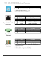
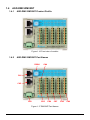
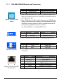
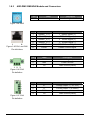
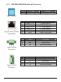
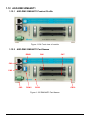
ASD-DMC-RM64MN Module and Connectors
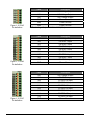
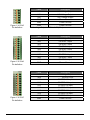
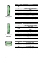
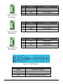
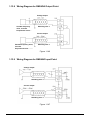
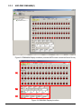
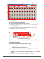
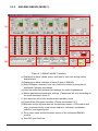
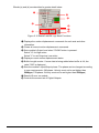
Figure 1.30 RSW1
1
8
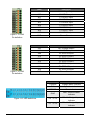
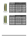
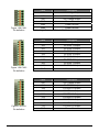
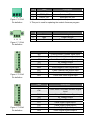
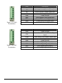
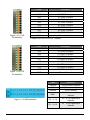
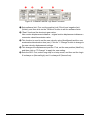
Figure 1.31 CN1 and CN2
Pin definitions
Pin
Label
Description
1~9
A~F
Node Number
Node ID
※ Invalid when dial is turned to 0, D ~ F
※ Each module takes up one Node ID
Pin
Label
Description
1
RS485T_1 (+)
1st RS485 Signal (+)
2
RS485T_1 (-)
1st RS485 Signal (-)
3
RS485T_2 (+)
2nd RS485 Signal (+)
6
RS485T_2 (-)
2nd RS485 Signal (-)
7
GND
RS485 Ground Signal
8
GND
RS485 Ground Signal
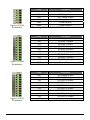
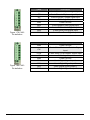
Pin
Label
Description
1
FG
Case Ground (Earth)
2
GND
Power Ground
3
24V
24V Voltage Input
1 2 3
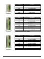
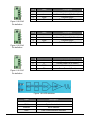
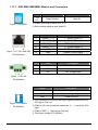
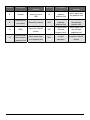
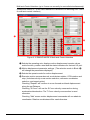
Figure 1.32 CN3
Pin definition
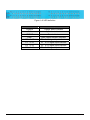
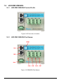
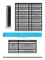
Figure 1.33 CN4
Pin definition
Revised April, 2012
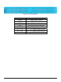
Label
Description
24V
24V Voltage Output
COM
Common Input Signal
GND
Power Ground
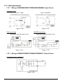
※ This connector is used with the Input signal common point for
Pull high or Pull low
※ COM to 24V → Low active (Pull high)
※ COM to GND → High active (Pull low)
※ Total Input voltage is 3.0A (Max)
1-15