1
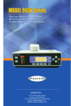
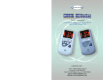
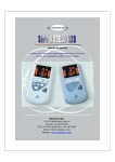
Model 100
Pulse Oximeter
User’s Manual
MEDIAID INC.
17517 Fabrica Way • Cerritos California 90703 USA
Tel.: 714-367-2848 • Fax: 714-367-2852
Web: www.mediaidinc.com
Email: [email protected]
POX010-100
Contents
Contents
Chapter 1: Principles of Operation .......................................................... 1
Intended Uses ........................................................................................................ 1
Principles of Pulse Oximetry ................................................................................. 1
Intrinsic Calibration ................................................................................................ 1
Principal Features .................................................................................................. 2
Cautions ................................................................................................................. 2
Preventing Device Complications and Faulty Readings...................................... 3
Chapter 2: Features, Indicators, and Symbols ...................................... 5
Model 100 Front View............................................................................................ 5
Model 100 Back View ............................................................................................ 6
LED Display............................................................................................................ 6
Pulse Oximeter Top View ...................................................................................... 7
Integral Finger Sensor Front/Top View................................................................. 7
Cable Adapter Front/Top View .............................................................................. 8
Cable Adapter and Integral Finger Sensor Bottom View..................................... 8
Symbols.................................................................................................................. 9
Chapter 3: Operating the Model 100 ......................................................11
Replacing the Battery ..........................................................................................11
Attaching the Integral Finger Sensor or the Cable Adapter...............................12
Removing the Integral Finger Sensor .................................................................13
Removing the Cable Adapter ..............................................................................13
Removing the Belt Clip ........................................................................................14
Attaching the Belt Clip .........................................................................................14
Powering On the Model 100................................................................................14
Powering Off the Model 100................................................................................15
Measuring Oxygen Saturation and Pulse Rate ..................................................15
Chapter 4: Maintaining the Model 100 ...................................................17
Cleaning the Model 100.......................................................................................17
Troubleshooting ...................................................................................................17
Chapter 5: Equipment Specifications....................................................19
General Specifications.........................................................................................19
Environmental Conditions....................................................................................20
Equipment Classification .....................................................................................21
- Contents 1 -
Contents
Chapter 6: Mediaid Inc. Limited Warranty ............................................23
Applicability of Warranty ......................................................................................23
Warranty Coverage..............................................................................................23
Mediaid Problem Correction Plan .......................................................................24
Owner’s Registration ...........................................................................................24
Chapter 7: User References ....................................................................25
Contact/Customer Service Information...............................................................25
Product Information..............................................................................................26
- Contents 2 -
Principles of Operation
Chapter 1:
Principles of Operation
Intended Uses
WARNING
The Mediaid Model 100 pulse
oximeter is intended to nonBefore using the Model 100,
invasively measure arterial oxygen
become thoroughly familiar
saturation and pulse rate in
with the information in this
hospitals,
physicians’
offices,
manual.
emergency medical facilities, or at
home. The Model 100 is not intended for continuous patient monitoring.
Principles of Pulse Oximetry
The Mediaid Model 100 pulse oximeter is designed to measure the
percentage of functional oxygenated hemoglobin to total hemoglobin.
Non-invasive arterial oxygen saturation measurement is obtained by
directing red and infrared light through a pulsating vascular bed. The
pulsating arterioles in the path of the light beam cause a change in the
amount of light detected by a photodiode. The pulse oximeter determines
the oxygen saturation of arterial blood by measuring the ratio of
transmitted red to infrared light within the pulse waveform. The nonpulsatile signal is removed electronically for the purpose of calculation.
Therefore, skin, bone, and other non-pulsating substances do not
interfere with the measurement
of arterial oxygen saturation.
Intrinsic Calibration
The light absorption by hemoglobin is wavelength-dependent. Mediaid
red and infrared LED wavelengths are tightly controlled by testing in
production. In addition, the LED intensity recorded at the detector is
automatically adjusted for amplitude; this allows Mediaid pulse oximetry
sensors to be used interchangeably without calibration.
-1-
Principles of Operation
Principle Features
The Mediaid Model 100 pulse
WARNING
oximeter is a portable, lightweight,
Do not use the Model 100 for
pocket-sized
instrument
that
continuous patient monitoring.
monitors functional arterial oxygen
saturation and pulse rate non-invasively.
The principal features of the Model 100 are as follows:
•
•
•
•
Gives an alternating readout of SpO2 percentage (%SpO2) and pulse
rate in beats per minute (BPM) on a 3-digit, 7-segment LED (lightemitting diode) display.
Can be used with either the Integral Finger Sensor or any Mediaid
pulse oximetry sensor that has a CompuShield® Connector that
attaches to the Cable Adapter.
Increases the longevity and functionality of the pulse oximeter with the
removable and replaceable sensor modules.
Performs approximately 1200 spot checks on a single 1.5 volt, AAsized alkaline battery (when using a Duracell® Ultra battery, which is
recommended).
Cautions
General Cautions
•
•
•
•
•
US federal law restricts this device to sale by or on the order of a
physician.
Become thoroughly familiar with the information in this User’s Manual
and all accompanying documents before using the Model 100.
Do not attempt to modify or repair the instrument—doing so voids the
warranty.
Dispose of this device according to governmental regulations.
Adhere to all cautions, stipulations, and instructions included with the
Integral Finger Sensor, the Cable Adapter., and all Mediaid sensors
used with the Cable Adapter..
Environmental Cautions
•
•
•
Do not use the instrument in the presence of flammable agents or
flammable anesthetics.
Do not immerse in liquid and do not allow any liquid to penetrate the instrument’s
interior.
Operate the pulse oximeter in normal light conditions.
-2-
Principles of Operation
•
•
•
•
Avoid bright light or glare on the sensing area to ensure correct
reading of the displays and indicators.
Keep the pulse oximeter away from MRI (Magnetic Resonance
Imaging) equipment.
Move the pulse oximeter away from other electromagnetic-emitting
equipment if you experience interference problems. This device
complies with electromagnetic compatibility standard EN 60601-1-2.
Keep away from equipment that emits x-ray alpha particles, beta
particles, neutron particles, or microwave emissions.
Battery Cautions
•
•
•
•
Use only 1.5 volt, AA-sized alkaline batteries (Duracell Ultra batteries
are recommended). Never use manganese batteries, lithium batteries,
or any other type of battery not specifically recommended. Use of
such batteries may damage the pulse oximeter.
Never dispose of batteries into fire, short-circuit the terminals, or
attempt to disassemble, heat, or recharge the batteries. Doing so may
damage the batteries and cause a fire, injury, or environmental
contamination.
Liquid leaking from the battery can cause skin burns or damage the
pulse oximeter. If a battery leaks inside the instrument, return the
pulse oximeter for servicing.
Remove the battery during shipment or if the Model 100 is to be idle
for several weeks.
Preventing Device Complications and Faulty Readings
To prevent device complications or faulty readings:
• Trim the patient’s long fingernails and remove artificial nails and thick
nail polish.
• Insert the patient’s finger completely into the Integral Finger Sensor.
• When using the Integral Finger Sensor, both the pulse oximeter and
the patient’s hand should rest on the same flat surface.
• Fit the sensor comfortably without constricting or compressing the
application site when using a sensor that is attached to the Cable
Adapter.
• Do not apply the sensor to anything but a well-perfused extremity.
• Do not apply the sensor on extremities that have blood pressure cuffs
or arterial or venous catheters.
-3-
Principles of Operation
•
•
•
•
•
•
•
•
•
Avoid extremity positions that could compromise venous return.
Keep sensors at heart level whenever possible.
Check for intravascular dyes, which may affect pulse oximeter
readings.
Turn off very bright lights, such as surgical, bilirubin, fluorescent, or
infrared heating if they interfere with sensor functioning. In cases
where such lights are unavoidable, cover the sensor site with an
opaque material.
Route sensor cords carefully.
Avoid applying excessive tension to the sensor or sensor cable.
Consider conditions affecting the hemoglobin dissociation curve when
interpreting pulse oximeter readings (such as intravascular dyes).
Keep patient movement to a minimum.
When not in use, do not wind the sensor cord around the oximeter.
-4-
Features, Indicators, and Symbols
Chapter 2:
Features, Indicators, and
Symbols
Model 100 Front View
A. Module Release
The Module Release mechanism
allows for removal of the Integral
Finger Sensor or the
Cable
Adapter
module
from
the
Model 100.
B. Module Connector
The Module Connector connects the
Integral Finger Sensor or the
Cable Adapter module to the
Model 100.
C. LED Display
The LED Display alternates between
showing the pulse rate and the
oxygen saturation values. The
LED Display also shows error
code numbers and functions.
D. Visual Pulse Indicator
The Visual Pulse Indicator is an orange LED that flashes with every
pulse detected by the Model 100.
-5-
Features, Indicators, and Symbols
Model 100 Back View
A. Module Release
The Module Release mechanism allows for
removal of either the Integral Finger Sensor
or the Cable Adapter module from the
Model 100.
B. Battery Compartment
The Battery Compartment holds a single 1.5
volt, AA-sized alkaline battery that provides
operating power for the Model 100.
C. Belt Clip
The removable Belt Clip provides a
convenient method of carrying the Model
100.
D. Belt Clip Retaining Screw
The Belt Clip Retaining Screw attaches the
Belt Clip to the Model 100.
LED Display
A. Oxygen Saturation Display
The Oxygen Saturation Display shows the
oxygen saturation values.
B. Oxygen Saturation Indicator
The Oxygen Saturation Indicator lights
whenever an oxygen saturation value is
displayed.
C. Low Battery Indicator
The Low Battery Indicator lights up
whenever the remaining operation time is
less than 30 minutes.
D. Pulse Rate Display
The Pulse Rate Display shows the pulse rate values.
E. Pulse Rate Indicator
The Pulse Rate Indicator lights up when a pulse rate value is displayed.
-6-
Features, Indicators, and Symbols
Pulse Oximeter Top View
A. Module Connector
The Module Connector connects the Integral
Finger Sensor or the Cable Adapter module
to the pulse oximeter.
B. Insertion Guides
The Insertion Guides align with the Insertion
Tabs on the Integral Finger Sensor or the
Cable Adapter to ensure proper attachment.
Integral Finger Sensor Front/Top View
A. Sensor Top Lever
The Sensor Top Lever is pressed to open
the sensor so that a finger can be
inserted. Pressing the Sensor Top
Lever when the Integral Finger Sensor
is attached powers on the Model 100.
B. Finger Insertion Area
The Finger Insertion Area is the location
for insertion of a finger or a thumb into
the sensor.
C. Insertion Tabs
The Insertion Tabs align with the Insertion Guides on the pulse oximeter
to ensure proper attachment.
-7-
Features, Indicators, and Symbols
Cable Adapter Front/Top View
A. Cable Adapter On/Off Key
The Cable Adapter On/Off key
powers on the pulse oximeter when
the Cable Adapter is attached.
B. CompuShield Connector
The
CompuShield
Connector
connects an appropriate Mediaid
sensor to the Cable Adapter.
C. Insertion Tabs
The Insertion Tabs align with the
Insertion Guides on the pulse oximeter to ensure proper attachment.
Cable Adapter and Integral Finger Sensor Bottom View
A. Spring Clip
The Spring Clip secures either
the Integral Finger Sensor or the
Cable Adapter to the pulse
oximeter.
B. Module Release
The Module Release mechanism
allows for removal of either the
Integral Finger Sensor or the
Cable Adapter from the pulse
oximeter.
C. Insertion Tabs
The Insertion Tabs align with the Insertion Guides on the pulse oximeter
to ensure proper attachment.
D. Rear Connector
The Rear Connector electrically connects Integral Finger Sensor or the
Cable Adapter to the pulse oximeter.
-8-
Features, Indicators, and Symbols
Symbols
Symbols
Definition
Cable Adapter On/Off
SpO2
Oxygen Saturation
BPM
Pulse Rate Indicator
Low Battery Indicator
Battery Polarity Symbol
Attention: Consult accompanying documents
Not anesthetic proof
Type BF equipment
Date of manufacture
RX Only
US federal law restricts this device to sale by or on the
order of a physician
-9-
Principe d’Utilisation
- 10 -
Operating the Model 100
Chapter 3:
Operating the Model 100
Replacing the Battery
The Model 100 is powered by a
CAUTION
single 1.5 volt, AA-sized
Always
adhere
to all of the
alkaline battery that will operate
cautions
listed
in “Battery
the instrument for
Cautions,”
in
Chapter
1.
approximately 1200 spot
checks (when using a Duracell
Ultra battery).
To replace the battery, complete the following steps.
1. Gently press down on the Battery Compartment door and push it out
of the pulse oximeter.
2. Insert the battery.
Follow the correct polarity indicated by the Battery Polarity symbol
located on the inside of the compartment.
3. Insert the tabs on the Battery Compartment Door into the Battery
Compartment and gently slide the door into place.
- 11 -
Operating the Model 100
Attaching the Integral Finger Sensor or the Cable
Adapter
To attach either the Integral Finger Sensor or the Cable Adapter to the
Model 100, complete the following steps.
CAUTION
To obtain accurate oximetry
readings, choose an
appropriate Mediaid pulse
oximeter and sensor according
to the intended use. Follow all
instructions stated within this
manual as well as those
included with each sensor.
FIGURE 1
NOTE
The Integral Finger Sensor or
the Cable Adapter can be left
connected to the pulse
oximeter.
FIGURE 2
1. Set the Integral Finger Sensor or the Cable Adapter module into the
pulse oximeter, pointing the Rear Connector of the module toward the
Module Connector of the pulse oximeter (Figure 1).
The arrow on the bottom of the module will point toward the LED
Display of the pulse oximeter.
2. Slide the Integral Finger Sensor or the Cable Adapter module
completely into the pulse oximeter (Figure 2).
The Insertion Tabs at the end of the module will fit into the Insertion
Guides on the pulse oximeter.
- 12 -
Operating the Model 100
Removing the Integral Finger Sensor
To remove the Integral Finger Sensor from
the Model 100, complete the following
steps.
1. Locate the Module Release mechanism
at the back of the instrument (just above
the label).
2. Push the pointed end of a paper clip
into the Module Release mechanism,
while simultaneously pushing gently
upward on the Sensor Top Lever
(Figure 3), until the Integral Finger Sensor
is released.
Slide the Integral Finger Sensor out of the
pulse oximeter.
FIGURE 3
Removing the Cable Adapter
To remove the Cable Adapter from the
pulse oximeter, complete the following
steps.
1. Locate the Module Release mechanism
at the back of the pulse oximeter (just
above the label).
2. Push the pointed end of a paper clip
into the Module Release mechanism,
while simultaneously pushing upward on
the Cable Adapter or pulling upward on
the attached sensor connector (Figure 4).
Slide the Cable Adapter out of the pulse
oximeter.
FIGURE 4
- 13 -
Operating the Model 100
Removing the Belt Clip
To remove the Belt Clip from
the Model 100, complete
the following steps.
1. Use a #1 Jeweler’s (small
Phillips) screwdriver to
remove the Belt Clip
Retaining Screw.
2. Remove the Belt Clip from
the pulse oximeter.
Attaching the Belt Clip
If the Belt Clip has been
removed from the pulse
oximeter, complete the
following steps to replace
it.
1. Place the flat part of the
Belt Clip on the back of the pulse oximeter, lining up the screw holes
on the Belt Clip and the pulse oximeter.
2. Place the Belt Clip Retaining Screw into the hole in the Belt Clip.
3. Use a #1 Jeweler’s (small Phillips) screwdriver to tighten the Belt Clip
Retaining Screw.
Powering On the Model 100
To power on the Model 100,
complete one of the following two
steps.
•
WARNING
To ensure personal safety and
proper operation of the pulse
oximeter, adhere to all
directions, warnings, cautions,
and policies stated within this
manual as well as those
included with each accessory.
If the Integral Finger Sensor is
attached, press the Sensor Top
Lever until the Model 100
powers on.
• If the Cable Adapter is
attached, press the Cable
Adapter On/Off key.
After power-on, the pulse oximeter tests the sensor availability, internal
functions, and the battery. The LED Display shows three dashes (- - -)
during the power-on tests, which last 1-2 seconds.
- 14 -
Operating the Model 100
When the pulse oximeter has successfully passed the power-on tests, it
begins measuring oxygen saturation and pulse rate data. If the battery
is low, the Low Battery Indicator will light. An error code will show if
any other malfunction occurs. See “Troubleshooting,” in Chapter 4, for
error code interpretation.
Powering Off the Model 100
To power off the pulse oximeter,
WARNING
complete one of the following
To ensure personal safety and
steps.
proper operation of the pulse
• If the Integral Finger Sensor is
oximeter, adhere to all
attached, remove the finger
directions,
warnings, cautions,
from the sensor.
and policies stated within this
• If the Cable Adapter is
manual as well as those
attached, either press the
included with each accessory.
On/Off key or disconnect the
sensor from the Cable Adapter.
If the pulse oximeter cannot detect oxygen saturation or pulse rate, or if
the finger is positioned incorrectly, it will power off automatically.
Measuring Oxygen Saturation and Pulse Rate
The Model 100 displays pulse oximetry data whenever a sensor is
attached to a patient and the monitoring site has sufficient perfusion.
Pulse oximetry data can be viewed on the LED Display, as follows:
• Oxygen saturation values display for 7.5 seconds.
• Pulse rate values display for 2.5 seconds.
To measure pulse oximetry data, complete the following steps.
1. Apply the sensor to the patient.
Either insert the patient’s finger into the Integral Finger Sensor, or
apply the sensor that is attached to the Cable Adapter.
2. If the Cable Adapter is attached, press the Cable Adapter On/Off key
to power on the Model 100.
The LED Display shows three dashes (- - -) for 1-2 seconds while the
Model 100 performs the power-on tests.
The Pulse Indicator begins to blink, signalling that the Model 100 is
measuring a site with sufficient perfusion.
3. If the Pulse Indicator does not blink, adjust the sensor position.
- 15 -
Operating the Model 100
After the power-on tests, the following information shows on the
Model 100:
• With each pulse detected by the pulse oximeter, the Vistual Pulse
Indicator flashes.
• SpO2 values show on the LED Display when the Oxygen Saturation
Indicator lights.
• Pulse rate values show on the LED Display when the Pulse Rate
Indicator lights.
The following conditions apply when the Model 100 cannot detect pulse
rate or oxygen saturation values:
• If the Model 100 cannot detect a pulse rate (but can detect oxygen
saturation values), three dashes (- - -) will show on the LED Display
each time the Pulse Rate Indicator lights.
• If the Model 100 cannot detect oxygen saturation values (but can
detect a pulse rate), three dashes (- - -) will show on the LED Display
each time the Oxygen Saturation Indicator lights.
• If the Model 100 can detect neither a pulse rate nor oxygen saturation
values, it will power off automatically.
- 16 -
Maintaining the Model 100
Chapter 4:
Maintaining the Model 100
Cleaning the Model 100
CAUTION
The Mediaid Model 100 Pulse
There are no user-serviceable
Oximeter, the Integral Finger
parts or adjustments inside the
Sensor, and the Cable Adapter
Model 100. Do not attempt to
can be wiped clean with a soft
open the instrument case—any
cloth
lightly
dampened
with
attempt to open the instrument
isopropyl alcohol, a glutaraldehyde
voids the Mediaid warranty.
solution, or soap and water. Do not
Refer to the information in
immerse in liquid or allow any
“Mediaid Problem Correction
liquid to penetrate the interior of
Plan,” in Chapter 6, for service
the pulse oximeter. Avoid caustic
information.
or abrasive cleaners that will mar
the case or the sensors. Use extra care in cleaning the LED Display
window to avoid scratching the finish.
Troubleshooting
Whenever an error occurs, the pulse oximeter displays the letters “Err”
(error) for 2 seconds, and then displays the error code for 2 seconds.
Error messages cycle three times, then the pulse oximeter powers off.
Table 1 explains the error code messages and gives possible solutions
to the problems described in the messages.
- 17 -
Maintaining the Model 100
Table 1
Error Code
Description
2
The pulse oximeter will
not power off
3
The battery needs to be
replaced.
7,8
The Cable Adapter, the
sensor attached to the
Cable Adapter, or the
Integral Finger Sensor is
malfunctioning.
11
The pulse oximeter
cannot detect the
sensor, either because
of a sensor malfuntion or
the sensor is not
properly attached.
4,6,9,10,12,13,14,15
An internal failure has
occurred.
Solution
Remove the battery and
contact Mediaid Inc.
Technical Support.
Replace the battery. If
replacing it does not
clear the code, contact
Mediaid Inc. Technical
Support.
Replace the Integral
Finger Sensor or the
sensor attached to The
Cable Adapter with a
functioning sensor. If
replacing the sensor
does not clear the code,
try replacing the Cable
Adapter. If the error
code persists, contact
Mediaid Inc. Technical
Support.
Remove, then reattach
the Cable Adapter and
the sensor connected to
the Cable Adapter, or the
Integral Finger Sensor.
If reattaching does not
clear the error code,
contact Mediaid Inc.
Technical Support.
Contact Mediaid Inc.
Technical Support.
If any other error codes appear, contact Mediaid Technical Support.
- 18 -
Equipment Specification
Chapter 5:
Equipment Specifications
General Specifications
Dimensions
Size:
4.73 x 1.82 x 0.96 in
12 x 4.67 x 2.46 cm
Weight: 4.1 oz/113 g w/Cable Adapter
3.9 oz/111 g w/Integral Finger Sensor
(weight includes battery)
Display
Type:
Display Rate
SpO2: Every 7.5 seconds
BPM:
Resolution
3-digit, 7-segment LED display
Every 2.5 seconds
SpO2: 1%
Pulse: 1 BPM
Range
SpO2: 20 to 100%
Pulse: 25 to 250 BPM
Accuracy
SpO2: 100 to 70%
± 2%
69 to 60%
± 3%
< 60%
unspecified
Pulse: 25 to 200 BPM ± 2 BPM, or 2%
> 200 BPM
± 3%
Response Time SpO2: 8 seconds for 80% of patients
Pulse: 8 seconds for 80% of patients
- 19 -
Equipment Specification
Sensors
The Integral Finger Sensor, or any Mediaid pulse oximeter sensor with
the CompuShield Connector for use with the Cable Adapter, is
compatible with the Model 100.
Red LED
IR LED
Wavelength:
660 ± 2 nm
Energy:
60 uW
Wavelength:
910 ± 10 nm
Energy:
150 uW
Power Source
Battery Type:
One 1.5 volt, AA-sized alkaline battery
(Duracell Ultra recommended)
Battery Life:
Approximately 1200 Spot Checks (using Duracell Ultra)
NOTE: Battery life varies with usage conditions and battery brand.
Environmental Conditions
Operating Temperature
0° to 40° C
32° to 104° F
Storage/Transport Temperature
-40° to 70° C
-40° to 158° F
Operational Relative Humidity
30 to 75%
Storage/Transport Relative Humidity
10 to 100% (including condensation)
- 20 -
Equipment Specification
Operational Atmospheric Pressure
700 to 1060 hPa
Storage/Transport Atmospheric Pressure
500 to 1060 hPa
Equipment Classification
The Mediaid Model 100 Pulse Oximeter is classified according to
CAN/CSA C22.2, No. 601-1, IEC 601-1, Part 1, Section 1, Subclause 5,
as follows:
•
Type of protection against electric shock:
Internally powered, Type BF applied parts.
• Degree of protection against harmful ingress of water:
Ordinary equipment.
• Degree of safety of application in the presence of a flammable
anesthetic mixture with air, or with oxygen or nitrous oxide:
This equipment is not suitable for use in the presence of a
flammable anesthetic mixture with air, or with oxygen or nitrous oxide.
- 21 -
Principe d’Utilisation
- 22 -
Mediaid Inc. Limited Warranty
Chapter 6:
Mediaid Inc. Limited
Warranty
Applicability of Warranty
This warranty covers only the
NOTE
Mediaid Model 100 pulse oximeter
This product is sold by Mediaid
and accessories as indicated. It is
Inc. (referred to as Mediaid)
not extended to other products or
under the warranties set forth
components that the customer
herein.
uses in conjunction with Mediaid
products. This warranty shall not apply if the manufacturer determines
that the product has been damaged due to abuse, misuse,
misapplication, accident, negligence, tampering, or as a result of service
or modification by anyone other than an authorized Mediaid service
technician. Opening of the sealed enclosure or altering of the serial
number voids the Mediaid Warranty. Use of equipment contrary to or
inconsistent with the User’s Manual will also void the warranty.
Warranty Coverage
Mediaid warrants that the Model 100 enclosed with this warranty will
conform to the manufacturer’s specifications and shall be free from
defects in workmanship and materials for a period of two years from the
date of purchase. Batteries and accessories are excluded from this
warranty. The Integral Finger Sensor and the Cable Adapter are
warranted according to information on their respective instruction sheets.
This warranty does not cover any damage done to the equipment during
shipping, which shall be the sole responsibility of the transportation
company.
There are no warranties, expressed or implied, which extend beyond the
warranties set forth herein. Mediaid makes no warranty of
merchantability or fitness for a particular purpose with respect to the
product or parts thereof. This warranty gives you specific legal rights.
You may have other legal rights which vary from state to state (or
- 23 -
Mediaid Inc. Limited Warranty
country to country). Mediaid will not be liable to the user for incidental or
consequential damage or loss arising out of the user’s inability to use this
product.
Mediaid Problem Correction Plan
Should the Mediaid product prove to be defective, contact Mediaid by
telephone at:
1.714.367.2848
[email protected]
Have the product and serial numbers available when calling. Mediaid will
then issue a Return Authorization Number (RAN). Return the instrument
securely packaged in its original shipping carton (or equivalent
packaging), and include the RAN.
Mediaid will repair any faulty workmanship and will either repair or
replace (at our option) any defective part with new or refurbished parts.
For non-warranty repairs, the customer will be charged the current repair
rate at the time of receipt by Mediaid. All transportation charges shall be
the customer’s responsibility.
Always read the user’s manual carefully. The information included in the
User’s Manual will assist the user in preventing equipment misuse and
ensuring patient safety. Operation of the equipment in a manner contrary
to or inconsistent with the User’s Manual voids the warranty.
Owner’s Registration
To assist Mediaid in better serving the user, please complete the
included Warranty Registration Card and return it to:
Mediaid Inc
17517 Fabrica Way, Suite H
Cerritos, CA 90703 USA
- 24 -
User Information
Chapter 7:
User Information
Contact/Customer Service Information
For information on other Mediaid Inc. products, visit the Mediaid Inc.
home page on the web at www.mediaidinc.com, or contact us at:
Customer Service
17517 Fabrica Way, Suite H
Cerritos, CA 90703 USA
Returns Department
17517 Fabrica Way, Suite H
Cerritos, CA 90703 USA
Phone
714.367.2848
Fax
714.367.2852
Email
[email protected]
- 25 -
User Information
Product Information
To better assist customers, Mediaid recommends that all users write
down all pertinent product and warranty information in the spaces
provided below:
Model 100
Product Number: POX010-100
Serial Number:
Warranty Expiration Date:
Integral Finger Sensor
Product Number: POX050-750-1S
Serial Number:
Warranty Expiration Date:
Cable Adapter
Product Number: POX055-200-1S
Serial Number:
Warranty Expiration Date:
- 26 -