1
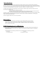
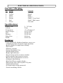
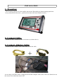
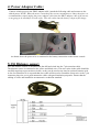
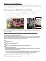
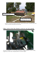
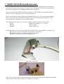
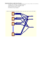
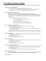
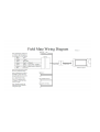
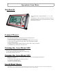
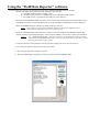
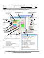
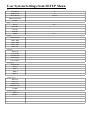
Field Mate Area meter users guide.
VERSION 1.0
www.areameters.com
FIELD MATE USER MANUAL
tm
VERSION 1.2
If you Need to Call Customer Service
Please complete the following information for future
reference:
Field Mate Model* :............................................................
Serial Number * :................................................................
Date Purchased :.................................................................
Place of Purchase:...............................................................
* The serial/Model Number is displayed in the
Information Screens of the meter.
Copyright
All information contained in this user's guide is the
property of G-Tech NZ Ltd. All rights reserved. This
user's guide may not be , in whole or in part, be copied,
photocopied, reproduced, stored, or reduced to any
electronic medium or machine readable form, without
permisssion from G-Tech NZ Ltd.
IMPORTANT:
To obtain the highest Precision Surface Area / Work done Measurement:
–
–
–
–
The Speed sensor must be mounted on a wheel that is not subject to slip or spin during the
Surface Area Measurement mode. ie: When not in Hold mode.
Straight line operation is best suited to surface area mesurement as tight turns of
implement / vehical will result in a lesser or greater number of wheel turns. High
precision mesurement is best achieved by working to straight lines.
Wheel size and implement working width should be measured as required to ensure the
sizes used by the meter, reflect the real world sizes of the implement / vehical. It is the
users responsiblity to ensure the sizes in the meter are correct.
When Work is not being measured, the meter must indicate this by going into Hold
mode.ie: Hold light on, "HOLD" flashing on working screen.
Introduction:
The FIELD MATE Area Meter has been developed to calculate Land area, distance travelled during seed drilling
operations. The meter will also record drilling hours and timed stopped. While drilling the meter can display the drilling
rate in hectare per hour and if required a low seed alarm can be attached to inform the user that the seed level has reached
a certain level. All measurements are in the metric, eg: hectares, kilometers, centimeters, millimeters.
A distance sensor mounted on the input shaft to the colter gearbox. With this single sensor the area meter can work
out if the drill is planting or not.
- Enter the DRILLING WIDTH into the meter.
- Enter the DISTANCE TRAVELLED PULSE, which is the distance travelled by the drill each time
the magnet on the input shaft to the colter gearbox passes the Distance sensor.
The meter is ready to use when the drill width and distance travelled per distance sensor pulse have been entered, and the
meter will measure area drilled, drilling rate,speed etc. When the drill is lifted at the head lands (ie: drilling stops),
surface area measurement also stops.
The unit is rugged, reliable, easy to use, fits any seed drill.
Warranty :
1 Year return to factory Warranty on Area Meter, sensors and Downloading support hardware.
Please ensure you agree to the warrantry conditions before proceeding to purchase this product,
read the warranty form at the end of this user guide. Installation wiring to sensors and wear and
tear on connectors not covered.
EMI Emmisssion Certification:
Electro magnetic interference emmission certification are a series of tests that required to be passed before an
electronic device can be sold. These test are related to how much electron magnetic radiation is emmitted by
an electronic device.
The Area meter has the following certifications and is suitable for sale in the following countries:
Certification
Countries
C-Tick Z874 Class B
New Zealand, Australia
ELECTRICAL SPECIFICATIONS
Pin outs 7 Pin plug:
Pin
1
6
5
3
2
7
7
Colour
Black
Yellow
White
Green
Brown
Red
Power
Function
Earth
Speed
Hold
Shaft 1
Shaft 2 , Low Seed
Shaft 3, Bale count
Not used
Specifications:
Supply volts
Current
Temperature
Input voltages
Area
Distance
Wheel Size
Width
:
:
:
:
:
:
:
:
5 – 30 Volts
25ma
-5 to 55 degree/C
0 to 30 Volts
999.99 hect
999.99 km
999.9 cm
9999.9 cm
Features:
-Large graphically displayed numbers, easy to see.
-3 button operation, for quick simple operation.
-Backlit display for night time working.
-Dust sealed.
-Mositure resistant.
-Strong Aluminium Case.
-Internal alarm buzzer.
-Bright light indicators.
-Easy fit mount sticks to tractor window.
-Quick transfer from tractor to tractor.
-Reports all job information on screen.
-Automatic data Backup.
-Help Desk Phone number display.
-Data storage time with out power 20 years.
-Aluminum enclosure.
-All inputs high voltage protected.
-Various mounting choices.
INSTALLATION
1: Mounting:
The mounting options are velcro and the ram mount. Depending on what mounting option has
been purchased with the meter , position the mount in the most suitable location.
2: Connect Cable:
Attach the DB15 extension cable to the meter (as shown above).
3: Connect Adaptor Cable:
Attach the DB15 adaptor cable to the DB15 extension cable.
+
As seen above the DB15 cable is plugged into the DB15 adaptor cable, these cables are shown here on
the tractor floor behind the tractor seat.
4: Power Adaptor Cable:
Connect vehicle power to the DB15 adaptor cable. Attach the following cable and connect to the
vehical power. NOTE: When the meter is turned off the current consumption is 20ma, therefore it is
recommended to simply unplug the power adaptor cable from the DB15 adaptor cable if the tractor
is not going to be started for several weeks. This will ensure that the battery is kept in full charge.
As shown above the power wire is connected to the battery connection on the tractor console.
5: Fit Distance sensor:
Here the distance sensors is mounted onto the drill and wired into the 7 pin extension cable.
The distance sensor is connected to the yellow and black wires. The extra wires in the cable should be
carefully taped up to prevent short circuits, as they can be used at any time for optional features such
as low seed detection. It is expected that extra cable will be used to extend the sensor wire to the 7 pin
connector plug wire, use a good automotive cable with good insulation properties. Ensure that the
cabling is secure and installed to an automotive technician standard.
Distance sensor installation:
This sensor is used to measure the distance travelled by the drill. This sensor when triggered lets the
meter know that a certian distance has been travelled, from this signal the meter will compute speed,
area, rate and distance drilled.
Mounting option to suit a RUN/HOLD setting of SPEEDO:
This mounting method will see the distance sensor get mounted to monitor the magnet attactched to
the drill colter shaft gearbox output shaft.
Below are picture of this type of installation. The "RUN/HOLD" setting is "SPEEDO" for this
sensor mounting choice. When the drill is lifted to stop planting, the magnet mounted onto the drill
colter shaft gearbox output shaft with stop rotating; the meter will detect this and the speed is set to
zero and lastly the meter will go into HOLD mode.
MAGNET
SENSOR
The above drill had the distance sensor magnet mounted on a shaft that rotated once every 15
meters. The magnet should pass the end on the sensor. An air gap of up to 1cm is allowed between
the sensor and magnet.
Measure the distance travelled by the drill for one distance sensor pulse.
Distance pulse calibration instruction:
After the Distance Pulse sensor and magnet have been installed we now need to enter the distance
travelled by the drill each time the distance sensor magnet passes the distance sensor. Follow the
below instructions to enter the distance travelled pulse distance.
Step 1:
Power up the meter.
Step 2:
Scroll down to the SETUP screen.
Step 3:
Enter the SETUP screen and scroll down to the PULSE DIST setting.
Step 4:
Enter the PULSE DIST screen.
In this screen each time the Magnet passes the Distance Sensor the meter will beep. This beep is
used to set up the distance measurement.
A: Drive the tractor forward with drill attached and drill drilling and stop immediately the first
beep is heard. When the beep is heard, mark where the drill is currently positioned.
B: Drive forward until the meter beeps a second time and stop immediately.
C: Measure the distance travelled by the drill between the 2 beeps.
Step 5:
Distance pulse sensor calibration complete.
Drilling width.Entered into the
WIDTH setup screen.
Distance travelled by the drill
per drill pulse. Enter into the
DIST PULSE setup screen.
Distance travelled by the drill per drill pulse. Measure this distance accurately with a tape
measure and enter this number into the meter.
Other places that the distance sensors can be located.
The above installation is on a Great Plains drill and the FieldMate Distance sensors is being
triggered by an older style competing brand of area meter magnet.
7: SEED SENSOR Installation info:
The FieldMate Seed Sensor is an optical seed detection device. A light beam is used to detect
the presence of seed, if no seed is covering the sensor, the light beam will be uninterupted and
the sensor will signal to the FieldMate meter that the seed is low.
The meter will turn the STATUS LED on, display the "LOW SEED" message and sound the
buzzer every 2 seconds when a low seed state is detected.
Each seed sensor has a wiring connection information sticker on it. The sensor requires battery
power, a ground connection and an the output wire to be connected back to the meter. These
connections can be found in the 7 pin cable assembly.
The following wires from the 7 pin cable assembly should be connected to the meter.
BLUE
Sensor battery positive, 5 - 30 volts
BLACK
Sensor ground
GREEN
Sensor output wire.
If multiple sensors are used in the seed bin, then simply connect all common wire together, eg:
BLUE wire connects to all sensor battery positive connections.
BLACK wire connects to all sensor ground connections.
GREEN wire connects to all sensor output wires.
Seed sensor front view.
Back view of seed sensor. The sensor is mounted into the seed bin in this up right position. Mount
onto the side of the seed bin with the 2 mounting screws shown.
Instruction of how to enable the seed sensor:
(NOTE: The Seed Sensor option must be factory enabled for this setup to work. Contact your dealer for more information).
- Turn the meter on and go to the SETUP screen 3.
- In SETUP screen 3 scroll to SEED STATE.
- Enter Seed State and set to POS.
- Seed Sensor set up complete.
WIRING UP MULTIPLE SEED SENSORS. CONNECT INTO THE 7 PIN CONNECTOR CABLE.
BATT +
GND
OUT
SEED SENSOR 1
BATT +
BATT +
GND
OUT
GND
SEED SENSOR 2
BATT +
GND
OUT
SEED SENSOR 3
OUT
BATT +
GND
OUT
SEED SENSOR n
8: Configure the Meter Settings:
Now that the area meter has been wired up, the area meter needs the following settings configured.
STEP 1. Enter width information:
- Goto the first SETUP screen. Setup the width for seed drilling.
1: Enter the seed drilling width as the WIDTH number. Scoll down to the WIDTH
number, hold 5 or 6buttons to enter the WIDTH width setup screen.
STEP 2. Setup Pulse Distance length:
- Goto the first SETUP screen. Setup the Pulse distance for seed drilling.
- Scroll down to the PULSE DIST screen. Enter the distance travelled by the drill each
time the distance sensor is triggered by the magnet on the drill colter shaft gearbox input
shaft, as it turns 1 complete turn. In this screen the meter will beep every time the sensor
is triggered.
One method of measuring the wheel size is to:
1. Drive forward and stop when the meter beeps.
2. Mark where the drill is.
3. Drive forward stopping at the next beep.
4. Measure the distance between these two marks.
5. Enter this number into the PULSE DIST screen.
STEP 3. Setup the RUN/HOLD mode:
- Goto the first SETUP screen. Setup the HOLD mode for seed drilling.
1: Enter the RUN/HOLD screen.
2: Set the HOLD option to SPEEDO if the magnet on the colter shaft stops turning
when the drill is lifted.
(Alternative modes are EXT LOW or EXT HIGH, use these if a hold sensor is used to detect the
drill rising and lowering. For more information on this option please contact your local dealer.)
STEP 4. Setup Date:
- Set current date so all jobs started will date stamped with the correct date. Allowing Job
report simple and easy to manage.
1. Goto SETUP screen 2
2. Scroll to DATE and set the current date.
STEP 5. Setup Time:
- Set current date so all jobs started will date stamped with the correct date. Allowing Job
report simple and easy to manage.
1. Goto SETUP screen 2
2. Scroll to TIME and set the current time.
STEP 6. Setup LOW SEED Sensor:
- If a Low Seed sensor is connected to the Meter and the Low Seed Option is enabled, then
it is possible to configure the low seed sensor as an active NEGative or POSitive state.
1. Goto SETUP screen 3
2. Scroll to SEED STATE, adjust the setting to suit the seed sensor used.
STEP 7. Fill in Setup page:
At the end of this book is a "User settings page". Record the meters setup here, if the meter
gives trouble is is a good idea to see if the original setups have been changed.
Setup Complete.
Operation of Area Meter
Keyboard:
The computer has 3 keyboard buttons, 5 or 6 and
“ON”.
The 4th button is the reset button that allows the user to
quickly and simply clear call job information by simply
holding this key down. .
Connect Power:
The following information is displayed on the Area Meter Screen.
1: System boots up displaying boot information.
2: Unit serial number , model type eg: FM2-DRILL PRO, the current job.
3: Options that are enabled on this area meter. Eg: LOW SEED ALARM.
4: Current date and time.
5: Displays current number and description of the job that is being worked on.
6: FieldMate Logo followed by the main menu.
Turning the Area Meter Off:
When unit is on hold down the "ON" button.
1: Unit will save all totals and display the company logo.
2: LCD will go blank, unit is off.
Turning the Area Meter ON:
When unit is off hold down or quick press the "ON" button. The following information is
displayed on screen.
1: Area meter Job, Model and unit type eg: metric.
2: Job number and description.
3: Displays system date and time..
Scroll Main Menu:
Using the 5 or 6 buttons move up and down the menu options. The double size text is the selected menu.
Enter any of the selected menu items by a quick press of the "ON" button.
Job Menu:
Selecting a JOB:
This is done when a job is to be reset or restarted. A FieldMate FM-DRILL PRO has 16 jobs and there fore selecting
any of these jobs can be done by this method. A Job that has a "XX.XXX.XX" in the date location is an un allocated
job.
1: In the Main Menu scroll to JOB.
2: Quick Press “ON” to enter a JOB. Scroll to JOB using the 5or6 keys.
3: Hold 5or6 to select the job for adjusting.
4: Scroll to SELECT in the JOB SETUP screen Using 5or6. At SELECT hold 5or6 to select the job.
This job will be the current Job that work is logged to. Date and Time renewed . Job Totals and Job Name remain
untouched.
Reset a JOB:
1: In Main Menu scroll to JOB.
2:Quick Press “ON” to enter JOB. Scroll to JOB using the 5or6 keys.
3: Hold 5or6 to select the job for adjusting.
4:Scroll to RESET in the JOB SETUP screen Using 5or6.
5: At RESET hold 5or6 to reset the job. All Totals, Date, Time and Name for this job will be cleared.
Caution: Data cannot be recovered after this event.
Name a JOB:
1: In Main Menu scroll to JOB.
2: Quick Press “ON” to enter JOB. Scroll to JOB using the 5or6 keys.
3: Hold 5or6 to select the job for adjusting.
4: Scroll to NAME in the JOB SETUP screen Using 5or6. At NAME hold
5or6 to name the job.
5: At the NAME job screen 5 will change letter, 6 will goto the next letter
space. A maximum of 11 letters can be entered.
6: Quick press “ON” to exit.
View a JOB:
1: In Main Menu scroll to JOB.
2: Quick Press “ON” to enter JOB. Scroll to JOB using the 5or6 keys.
3: Hold 5or6 to select the job for adjusting.
4: Scroll to VIEW in the JOB SETUP screen Using 5or6. At VIEW hold
5or6 to select the job. Report screen will be displayed.
5 : Use 5or6to scroll through the job report.
6: Quick press “ON” to exit. Viewing job does not unset the selected job.
7: When exiting to the Main Menu, the Job Report is set back to the Current Selected Job Number.
Operate Menu:
1: In Main Menu scroll to OPERATE .
2: Quick Press “ON” to enter OPERATE Mode.
3: Use the 5 to display the following information types:
- AREA
- AREA sub (Reset this by holding down the 5or6 key)
- DISTANCE (Total distance travelled, combines the RUN and HOLD distances)
- RATE Hect/Hr (Calculates the amount of hect being worked per hour)
- SPEED
- Low Seed Alarm Status (optional)
- Shaft 1 RPM monitoring (optional)
- Shaft 2 RPM monitoring (optional)
- Shaft 3 RPM monitoring (optional)
4a: Delete the displayed total by holding down5or6 keys for 6 seconds.
4b: In Optional screens holding down the 5or6for 6 sec turns the alarm on/off.
5: Use the 6 key if the"Run Hold Mode" is "Keys", to switch the Field Mate
into/out of Hold.
6: Quick press "ON to Exit to Main Menu.
Area Menu:
1: In Main Menu scroll to AREA .
2: Quick Press “ON” to enter AREA Mode.
3: Use the 5 to display the following information types:
- AREA. Area amount for the current job.
- AREA SUB. Sub area total that can be reset any time.
- AREA Total. Area of all jobs done by the meter.
4: Use the 6 the key if the"Run Hold Mode" is Keys to switch the Field Mate into and out of Hold.
5: Quick press "ON to Exit to Main Menu.
Distance Menu:
1: In Main Menu scroll to DISTANCE .
2: Quick Press “ON” to enter DISTANCE Mode.
3: Use the 5 to display the following information types:
- DISTANCE. Distance travelled in RUN mode for the current job.
- DISTANCE SUB. Distance travelled in HOLD mode for the current job.
- DISTANCE TOTAL. Total distance travelled in HOLD and RUN mode for the current job.
4: Use the 6 key if the"Run Hold Mode" is "Keys", to switch the Field Mate
into and out of Hold.
5: Quick press "ON to Exit to Main Menu.
Calculator Menu: Designed for Rectangle shape bondary area calculation only.
1: In Main Menu scroll to CALCULATOR .
2: Quick Press “ON” to enter CALCULATOR Mode.
3: Use the 5 key to toggle between LENGTH and WIDTH distance recording.
While in Length or Width mode, if the machine travels, regardless if in Run
or Hold mode the distance is recorded to that total.
4: Press the 6 key to display the AREA result of the Width and Length
distances. In area mode the WIDTH or LENGTH numbers are not effected by
the machine moving.
4: Delete the displayed total by holding down5or6 keys for 6 seconds.
5: Quick press "ON to Exit to Main Menu.
Speed Menu:
1: In Main Menu scroll to SPEED .
2: Quick Press “ON” to enter SPEED Mode.
3: Use the 5 key to display the following information types:
- RATE , Hect/Hr.
- Time in Run mode.
- Time in Hold mode.
- Total job time.
- Max speed.
- Average Speed.
- Temperature.
- Time.
- Date.
- Area of current job.
- Distance or current job.
- Working machine width.
4: Delete the displayed total by holding down5or6 keys for 6 seconds.
5: Use the 6 key if the"Run Hold Mode" is "Keys", to switch the Field Mate
into and out of Hold.
6: Quick press "ON to Exit to Main Menu.
Setup Menu:
1: In Main Menu scroll to SETUP .
2: Quick Press “ON” to enter SETUP Mode.
3: Use the 5or6 keys to toggle scroll through the various setup options.
4: When at the required Setup option, to enter the Option hold down 5or6
key to enter the Setup mode for the Option.
5: When in the Option use the 5or6 keys to adjust the options settings. EG:
Screen 1:
- CONTRAST. Allows display clarity to be set up.
- DEBOUNCE. Allows meter to monitor extremly slow coulter shaft typically set to 10% .
- RUN / HOLD. The meter will go into HOLD mode as define be the setting here. For a Seed Drill,
RUN/HOLD setting would be the "SPEEDO". When the when the Drill is drilling, the
colter gearbox input shaft turns, the meter is in RUN mode. The meter is in HOLD mode
when the colter gearbox input shaft stops turning.
Other RUN/ HOLD modes:
- KEYS, controlled by the key board switch on the area meter, to switch to RUN mode.
- EXTERN LOW, external sensor will put meter in RUN mode when sensor is low, (0V).
- EXTERN HIGH, external sensor will put meter in RUN mode when sensor is high,(Batt V).
- SPEEDO, when speed is above 0 km/hr then the area meter is in RUN mode.
- MULTI WIDTH, monitor spray booms or triple mowers, have up to 5 width sections.
- BATT VOLTS, if battery voltage is above a certain voltage the meter will switch into RUN.
- VIBRATION, attach a vibration sensor to the meter, when meter moves it switches to RUN.
- PULSE DIST. Is the distance travelled by the drill each time the colter gearbox input shaft turns one
complete rev. This number is use to work out area, distance and drill speed.
- WIDTH.
Is the drilling width of the drill. This number is used to work out area cut.
Screen 2:
- DATE.
Set date here.
- SUPPORT.
Enter a HELP DESK Phone number here of who to ring for Area Meter support.
- UNIT ID.
Allows the unit to be named. Allows easy identification of a Meter.
- REPORT DATA Down load report control, this allows a Short or Long Job report format to be printed out.
- TIME.
Set time here.
Screen 3:
- SEED STATE. If low the low seed alarm is selected, this setting allows for eeither a positive or negative
switching sensor when the seed is low.
- SHAFT 1 RPM. SHAFT 1 lowest RPM setting. (Note**)
- SHAFT 2 RPM. SHAFT 2 lowest RPM setting. (Note**)
- SHAFT 3 RPM. SHAFT 3 lowest RPM setting. (Note**)
- Bail Counter.
Lock out time between bail counting. (Note**)
Screen 4:
- TRAM TYPE.
Round or line tramline mode. (Note**)
- TRAM SWATH.
Swath count between tramlining modes. (Note**)
- SEED DEBOUNCE.
Seed weight shaft sensor debounce time. (Note**)
- SEED WEIGHT.
Seed weight per revolution of the seed despensing shaft. (Note**)
- SEED COMPARE.
Weight of seed that when despenced with sound an alarm.(Note**)
Screen 5:
- MULTI WIDTH.ON/OFF control for variable width operational, eg sprayer and tripple mowers. (Note**)
- POLARITY.
Set the switching state of the width activation sensors. (Note**)
- WIDTH 1.
Variable width 1 distance. Can have up to 5 different width sections. (Note**)
- WIDTH 2.
Variable width 2 distance. Can have up to 5 different width sections.(Note**)
- WIDTH 3.
Variable width 3 distance. Can have up to 5 different width sections.(Note**)
Screen 6:
- BATT LEVEL. Set the battery level that the meter will go into run mode with. (Note**)
- AUTO SAVE. Time interval for the meter auto saving date when machine is not moving. (Note**)
- SIMPLE MODE.Display reduced menu. Reset job by holding the 5or6 keys in OPERATE mode while
displaying Area or Distance.
- IMP NAME.
Enter the machine being used here. This name with appear in the job report.
- TRAMLINE. Select the tramline control for colter soleniod clutches or linear actuator motors. (Note**)
Screen 7:
- Width 4.
Variable width 4 distance. Can have up to 5 different width sections. (Note**)
- Width 5.
Variable width 5 distance. Can have up to 5 different width sections.(Note**)
- GPS TRIGGER Turn on if the GPS mapping option is supplied, the GPS Map out wire with turn on/off as the
meter goes into run/hold.
- SPARE 2.
Spare capacity for future features. Call us and discuss your needs with us.
- SPARE 3.
Spare capacity for future features. Call us and discuss your needs with us.
** Note: Not required for a drilling operation.
Info Menu:
1: In Main Menu scroll to INFO .
2: Quick Press “ON” to enter INFO Mode.
3: Use the 5or6 keys to toggle scroll through the various information screens.
4: Display a varity of information that may be useful to the user, or in some cases a valuable tool in
working out if the area meter doing that job you want it to do. There are also low level information
here that give insight into the correct operation of the computer system that makes this area meter
what it is. Information may prove to be a useful tool used during installation.
Screen 1:
Screen 2:
Screen 3:
Screen 4:
Screen 5:
Screen 6:
Screen 7:
Screen 8:
Screen 9:
Screen 10:
Screen 11:
Screen 12:
Screen 13:
Screen 14:
Screen 15:
Screen 16:
Screen 17:
Screen 18:
Screen 19:
Screen 20:
Screen 21:
Screen 22:
- Meter logo graphic
- Help desk info
- Distance travelled pulse detection timing and detection info screen.
- Meter model infomation.
- Firmware release info
- Hours that the meter has been running, powered up and calculating area.
- LCD contrast setting and backlight voltage on/off control state.
- Temperature inside the meter.
- Voltage level applied to the meter.
- Serial number.
- Software error detection. Should be all 0.
- PWR is the number of power ups that the meter has had.
- BOD may get counts, this is a low power detection.
- Auto save count down timer.
- Average speed.
- Time and distance calculator numbers.
- Real Time Clock/Calendar timer information
- Run Hold state number.
- Area calculator numbers.
- Time number.
- Bale counter total.
- Area calculator numbers
- Shaft 1 – 3 info. RPM and detection counters.
- Job start detection number.
- Shaft or low seed detection error flag.
- Tramlining mode detection number and current tramlining numbers.
- Options screen. Shows if options have been enabled on this meter yet.
- Seed weight calculator screen.
- Variable width information.
- Widths number for all 5 widths supported and the total width.
- Spare screen.
- Calendar information.
- Uart buffer counters.
- Meter setup data numbers.
- Meter setup data numbers.
- Meter setup data numbers.
- Meter setup data numbers.
- Meter setup data numbers.
- States which features of the meter have been enabled and are ready to use by the meter.
5: Quick press "ON to Exit to Main Menu.
Report Menu:
1: In Main Menu scroll to REPORT .
2: Quick Press “ON” to enter REPORT Mode.
3: Use the 5or6 keys to toggle scroll through the various Report screens eg:
Screen 1:
- Displays job number + name.
Screen 2:
- Area worked in RUN mode.
Screen 3:
- Distance travelled in RUN mode.
- Distance travelled in HOLD mode.
Screen 4:
- Time moving in RUN mode.
- Time stopped in RUN mode.
Screen 5:
- Time moving in HOLD mode.
- Time stopped in HOLD mode.
Screen 6:
- Total time spent on this job.
Screen 7:
- Wheel turns in RUN mode.
- Wheel turns in HOLD mode.
Screen 8:
- Measurements used for this job. Wheel size and width.
Screen 9:
- JOB start time and date.
4: While at the first report screen hold down the 6 key to view the report of the next job. (PRO meters only)
5: While at the first report screen hold down the 5 key to view the report of ALL jobs total. (PRO meters only)
6: Quick press "ON to Exit to Main Menu.
Clearing the Meter.
*Hold the Reset key down for 5 seconds to delete the current job information.
Reset all Jobs:
1: Turn FIELD MATE tm Off.
2: Hold down the 5 key, "RESET ALL JOBS" is displayed and a scroll bar
counts across at the bottom of the screen.
3: Repeat step 2, 3 times to reset all the job totals.
4: The reset is complete when "RESET ALL JOBS DONE" is displayed.
Using the Meter.
Here is how to get going:
Setup the Meter in the Tractor.....
1: Install the meter into the tractor.
2: Install a sensor on the Drill colter gearbox input shaft.
2: Enter the drilling width into the meter.
3: Enter the distance travelled by drill per wheel turn.
4: Enter the date and time in the meter.
Start Drilling .....
1: Get to the paddock ready for drilling.
2: Reset the job in the meter. ( This will ensure that the last job drilled is cleared)
3: Start the job.
4: Job is now started , start drilling and at any time can easily see how much land has been drilled, rate
of drilling, time taken to drill the land, speed etc..
4: Job Complete!
5: See job report by going to the Report Menu.
Ready for next job ....
Using the "FieldMate Reporter" software.
Use this application to down load Job information from any FIELD MATE PRO series Area Meter.
1: Connect the Meter to the down load cable attached to the office PC.
A : The Meter should connect to a DB15 cable
B : The DB15 cable connects to a USB serial convert with DB15 adaptor fitted.
C : The USB coverter is connected to the USB port of the office PC.
2: Ensure that the FM-DRILL PRO is turned on. This software will automactically detect that a PRO version
FieldMate area meter is connected. When thsi occurs the "DOWN LOAD READY" button is displayed.
3: Start the FieldMate Reporter software by double clicking on the icon.
Note: If the reporter software is not installed, install from the factory supplied CD, or
down load the install files from www.areameters.com .
4: With the FM-DRILL PRO connected to the computer. Press the "DOWNLOAD READY" button. The
data has instantly returned fromthe meter. At this point the "PRINT" and "SAVE" buttons will be enabled.
Note 1 : If a " DOWNLOAD READY " button is not observed, check that the comm port that is
connected to the FM-DRILL PRO is the correct port. If required select the correct comm
port using the "Connect Port" button.
5: Once the job info is down loaded click on the job tabs to display the work done for each job.
6: To save the job info to a file press the "File Save" button.
7: Any or all job data can be printed at any time.
8: The Field Mate Reporter Application will only operate with the FM-DRILL PRO.
FieldMate Reporter Software
FieldMate Reporter Software can be used to transfer jobs information from the tractor to
the office. The software can be used to setup different tractor implements plus the client
name list that can be downloaded to the FieldMate Area Meter. Making job reporting
more informative, simple and quick to setup from the tractor. The FieldMate System is
suited to record work done for any tractor based agricultural activity.
Your implement
name goes here.
Max of 20 unique
implements can be setup.
Connect the meter to the
computer and press to
download jobs.
Press to save
jobs.
Working width of
this implement.
Select the long or
short job report
format.
Print Jobs.
Low seed alarm
control
View any job
Shaft monitoring
Dual and triple
mower setup.
Hay bale
counter setup
Transfer implement settings to
your Client-Database enabled
FieldMate Area Meter.
Job reports contain the following information
types:
- Area worked
- Time worked
- Date and time job started
- Implement used
- Client name.
If selected the report can contain: Hay bale
count and triple mower usage.
The FieldMate Area Meter can record all your machine based agricultural activites,
making invoicing and job tracking a breeze.
User System Settings from SETUP Menu.
1
CONTRAST
18
DEBOUNCE
10
RUN/HOLD
SPEEDO
DISTANCE PULSE
WIDTH
11
DATE
Now !
SUPPORT
UNIT ID
REPORT
TIME
111
SEED STATE
Shaft 1 RPM
Shaft 2 RPM
Shaft 3 RPM
Bail Count
1111
Tram Type
Tram Swath
Seed Debounce
Seed Weight
Seed Compare
11111
Multi Width
Polarity
Width 1
Width 2
Width 3
111111
Batt Level
Auto Save
Simple mode
Implement Name
Tramline
1111111
Width 4
Width 5
Now !
To validate Warranty Send a Photocopy of this document to: G-Tech NZ Ltd, PO Box 33223, Christchurch, New Zealand.
“FIELD MATE” EXPRESS LIMITED WARRANTY AND LIMITATION OF LIABILITY AGREEMENT
Where the word “FIELD MATE ” Area Meter appears it means the “FIELD MATE ” Area Meter circuit
board which includes a hard ware component and a leased Firmware component and/or Field Mate
Download Application, enclosure and wiring assembly only. Does not refer to any additional wiring added to
the “FIELD MATE ” Area Meter system during installation. The Firmware running in the “FIELD MATE ”
Area Meter and/or Field Mate Download Applicationis a zero fee leased copy and is not part of the “FIELD
MATE ” Area Meter purchase agreement. The Firmware and/or Field Mate Download Application lease
runs for the life of the product. G-Tech NZ Ltd remains the sole owner of the Firmware running in the
“FIELD MATE ” Area Meter and/or Field Mate Download Application.
TM
TM
TM
TM
TM
TM
Express Limited warranty.
G-TECH NZ LTD warrants the “FIELD MATETM” Area Meter to be free from defects in materials and workmanship for a period of 12 months from the
original date of sale to the end user or for a period of eighteen months from the date of factory shipment, whichever is sooner. If the product fails, customers
should at their cost return the “FIELD
MATE ”
TM
Area Meter to G-TECH NZ LTD. At the exclusive option of G-TECH NZ LTD , to either :
(b)
MATE ”Area Meter .
Replace the “FIELD MATE ” Area Meter .
(c)
If G-TECH NZ LTD is unable to replace / repair or correct firmware or hardware errors, G-TECH NZ LTD will refund the
(a)
Repair the “FIELD
TM
TM
price paid for the “FIELD
These are your sole remedies for any breach of warranty.
The warranty does not apply to “FIELD
MATE ”Area Meter .
TM
MATE ” Area Meter’s which have been improperly installed, subjected to extremes beyond the limits of GTM
TECH NZ LTD specifications, or which have been physically damaged. Nor does it apply to “FIELD MATETM” Area Meter’s found to be defective due
to abuse, electrical discharge, under temperature, over temperature, improper power application , damage resulting from acts of war or any damage incurred due
to acts of nature, salt or fresh water immersion or spray, or improper or unauthorized repair. Freight charges for products returned to G-TECH NZ LTD should be
pre-paid by the customer. G-TECH NZ LTD will prepay freight charges for returning the “FIELD
MATE ” Area Meter to the customer, provided that
TM
the “FIELD MATETM” Area Meter proved defective under the terms and conditions of the warranty.
Note:
Non G-TECH NZ LTD authorized individuals are discouraged from performing repairs on G-TECH NZ LTD products. Opening of the product by unauthorized
individuals will void the product warranty. Damage incurred as a result of non G-TECH NZ LTD service attempt will be considered abuse and repairs will not be
covered under warranty or standard repair pricing by G-TECH NZ LTD .
Limitation of liability
In no event will G-TECH NZ LTD or any person involved in the creation, production or distribution of the G-TECH NZ LTD “FIELD MATETM” Area
Meter be liable to you on account of any claim for any damages including any lost of profits , lost savings, or other special, incidental, consequential, or
exemplary damages, including but not limited to any damages assessed against or paid by you to any third party, rising out of the use, liability to use, quality or
performance of the G-TECH NZ LTD “FIELD MATETM” Area Meter , even if G-TECH NZ LTD or any such person or entity has been advised of the
possibility of damages or for any claim by any other party. G-TECH NZ LTD total liability under any provision of this agreement is in any case limited to
the amount actually paid by you for the “FIELD
MATE ” Area meter.
TM
Description of other rights and limitations.
Limitations on reverse engineering, Decompilation and Disassembly. You may not reverse engineer,
decompile, disassemble or upload the Firmware.
Rental. You may not rent or lease the “FIELD
MATE ”Area Meter .
Copyright. All title and copyrights in and to the “FIELD MATE ”Area Meter , the accompanying printed material and copies of the firmware are owned
by G-TECH NZ LTD. You may not copy the printed material accompanying the “FIELD MATE ” Area Meter . All rights not specifically granted under
TM
TM
TM
this agreement are reserved by G-TECH NZ LTD.
ACCEPTANCE OF TERMS
I the under signed Purchaser of the “FIELD MATETM” Area Meter computer have read the above Warranty and Limitations of liability Agreement and agree to
the conditions and limitations as stated above.
Unit Serial Number
:
...............................................................................
Start Date of Agreement
:
...............................................................................
Purchaser Company Name
:
...............................................................................
Purchaser Address
:
..........................................................................................................................
..........................................................................................................................
Purchaser Name Printed
:
...............................................................................
Purchaser Signed
:
……………………….……….…………………..