1
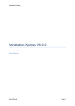
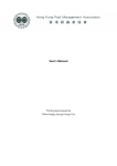
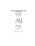
Operation
&
Maintenance
Manual
CoolSpace 16
CoolSpace 36
CoolSpace 48
Table of Contents:
1.0 Introduction
2.0 Unpacking your CoolSpace unit
3.0 Set-up of CoolSpace unit
3.1 3.2 4.0 Operating procedures
4.1 4.2 4.3 5.0 Maintenance and storage
5.1 5.2 5.3 5.4 6.0 Troubleshooting/Repair
6.1 6.2 6.3 7.0 Warranty
7.1 7.2 7.3 7.4 8.0 How evaporative cooling works
Connecting the water supply
Connecting the electrical supply
Filling the unit with water
Starting the fan
Starting the pump and adjusting the water flow
Removing the cooling media & accessing the inside of the unit
Daily maintenance
Periodic maintenance
Storage
Troubleshooting
Repair procedures
Technical support
Warranty form
Warranty parts
Optional accessories
Replacement parts
SIGNAL WORD DEFINITIONS
DANGER indicates an imminently hazardous situation which, if not avoided, WILL
result in death or serious injury.
WARNING indicates a potentially hazardous situation which, if not avoided, COULD
result in death or serious injury.
CAUTION indicates a potentially hazardous situation which, if not avoided, MAY
result in minor or moderate injury.
CAUTION used without the safety alert symbol indicates a potentially hazardous
situation which, if not avoided, MAY result in property damage.
As defined in ANSI Z535.4-2002
1.0 Introduction:
CoolSpace is a compact, self-contained, high-efficiency portable evaporative cooler
capable of lowering existing temperatures by as much as 30 degrees.
2.0 Unpacking your CoolSpace unit:
IMPORTANT
Carefully examine the carton for damage before opening. If the carton is damaged,
notify the shipping company immediately.
The 16” and smaller units are shipped in a cardboard box. Open the top panel and
lift the unit out. The larger units are shipped on a wooden skid stapled to a cardboard
cover and lid. The cardboard cover simply lifts off the CoolSpace unit after removing
the staples. The cooler must be lifted off the wooden skid.
3.0 Set-up of the COOL-SPACE unit:
The CoolSpace unit is factory tested and ready to use. The unit should be placed
on a level surface, and the casters locked to prevent inadvertent movement. Follow
instructions below to connect water and electrical supply.
3.1 Connecting the water supply:
The CoolSpace unit comes equipped with a female garden hose water source
connection. Attach the unit to a standard garden hose outlet for a water source. The
unit should not be attached to any water source with operating pressure above 60 psi.
Pressures above 60 psi must use a pressure regulator which may be purchased at your
local hardware store. If you have purchased the optional portable water tank, use a
standard garden hose (not provided) to connect the tank to the cooler.
CAUTION
Do not connect the COOL-SPACE® unit to any water source where water pressure
exceeds 60 psi. This will cause permanent damage to the unit.
3.2 Connecting the electrical supply:
All models utilize standard 120-volt power supply. The unit should be plugged into
a fused or circuit breaker protected 20 amp, 120 volt, 60 Hz circuit. If the unit is for
overseas operation or is custom built for a specific application, please consult the
factory for proper configuration. A ground fault circuit interrupter protected circuit is
strongly recommended.
IMPORTANT
The CoolSpace unit should be plugged into a fused or circuit breaker protected 20amp,
120 volt, and 60 Hz circuit. If the unit is for overseas operation or is custom built for
specific application, please consult the factory for proper configuration.
If an extension cord is required, refer to Table 2 for the proper 3-conducter heavy-duty
cord required. Table 1 shows the amperage requirements for the specific models.
CAUTION
Do not exceed the extension cord’s amperage ratings. Undersized extension cords
result in excessive voltage drops, which cause the electric motors to generate
excessive heat. This condition results in inefficient motor operation and premature
motor failure, WHICH WILL VOID THE WARRANTY
4.0 Operating procedures:
There are 3 factors to consider when determining where to place the CoolSpace unit.
1. Fresh air supply: The inlet side of the unit (pad side) requires a constant,
uninterrupted supply of fresh air for maximum performance. A distance of 3 ft clear
space is recommended.
2. Discharge air flow: The cool air discharged from the unit should be free of
obstruction to allow the air to circulate in order to maximize the cooling zone.
3. Ventilation: In order to operate at maximum effectiveness, it is helpful to have
provisions to remove the air discharged from the CoolSpace unit from the cooling
area. This ensures that the CoolSpace unit does not recirculate air that has already
been through the evaporative cooling process.
The CoolSpace unit must be placed on a level surface to operate correctly. The units
create an oval shaped air pattern that can reach out as far as 70 feet with large fans.
Obstacles such as racks and workbenches may interfere with the cooling zone. An
attempt should be made to locate the unit in such a manner that interruption of the air
pattern is held to a minimum. Multiple units may be required to cover larger areas.
When the CoolSpace unit is placed near a wall or other vertical obstruction, it is
recommended that there be a space of at least 3 feet between the back (pad side) of the
unit and the obstruction. This ensures that a clear supply of fresh air is able to get to
the inlet of the unit.
A platform or framework may be built to support the CoolSpace unit in order to
place the unit out of the way of obstacles. When constructing a framework, ensure
that it will not allow the CoolSpace unit to tip over. Also, the structure must be able
to accommodate the unit plus the added weight of the water in both the pads and the
reservoir.
16” Unit: 84 lbs. (unit) + 24 lbs. (pad operating weight) + 120 lbs. (15 gal. reservoir) = 228 lbs.
36” Unit: 295 lbs. (unit) + 60 lbs. (pad operating weight) + 384 lbs. (48 gal. reservoir) = 739 lbs.
48” Unit: 497 lbs. (unit) + 100 lbs. (pad operating weight) + 512 lbs. (64 gal. reservoir) = 1,109 lbs.
4.1 Filling the unit with water:
Once the CoolSpace unit has been hooked up to a water source as described in 3.1,
turn the water supply valve on and the unit will fill with water. The float valve will
shut off the water flow when the sump is full.
4.2 Starting the fan:
Turn the fan switch to HIGH speed on start-up, allow motor to reach maximum speed,
then set at Medium or Low.
IMPORTANT
DO NOT flood the pads with water, keep them moist. New pads take a few days to
become completely saturated. It is normal to have several dry streaks on the face of
the pads about 1 or 2 inches wide. If the streaks are larger or unevenly spaced, adjust
the flow control knob to allow more water to flow to the pads. NOTE: New pads
may also emanate an odor under initial operating conditions from the resin used to
construct the media. Flush the pads by running the pump without the fan running for
approximately 2 hours. Empty the sump and refill. Repeat if odor still exists.
4.3 Starting the pump and adjusting the water flow:
NOTE: Have fan running while adjusting the water flow.
Once the sump is full, the pump switch may be turned to the ‘ON’ position. The flow
control knob will need to be adjusted on initial start-up. It is located at the right side of
the unit, it controls the volume of water that is delivered to the top of the cooling pads.
CAUTION
Prolonged use of hard water without proper water treatment will create mineral
deposit build up causing the pump to fail which is “NOT COVERED BY
WARRANTY”
5.0 Maintenance and storage:
WARNING
ELECTRICAL SHOCK HAZARD
Disconnect the power supply before performing any service or maintenance on the
unit. Failure to do so may result in serious injury or death.
The CoolSpace unit is constructed of durable industrial grade components and
requires minimal maintenance. The housing is constructed of corrosion-free
polyethylene. The fan is galvanized for corrosion resistance. The motor is TEAO
moisture resistant specifically designed for wet applications. All other components are
designed for wet duty applications to ensure long life of the unit.
5.1 Removing the cooling media to access the inside of the unit:
In order to perform any maintenance on internal components, the cooling pads must
be removed to access the inside of the unit.
1. Use a wrench to remove the (2) bolts connecting the pad retainer (pad side) to the
housing.
2. Each pad can be tilted out of the unit and lifted out of the drain tray.
Note: Reinstall pads correctly.
5.2 Daily maintenance:
When shutting down the CoolSpace unit at the end of each workday, the pump
should be turned off approximately 15 minutes before the fan is turned off. This will
allow the pads to drain and dry out. This simple guideline will ensure long and
efficient pad life as well as help to control mildew and bacteria growth.
IMPORTANT
Shut off pump 15 minutes before shutting off fan to allow pads to drain and dry out.
This will help pad life and operation and control mildew growth.
5.3 Periodic maintenance:
Depending on how often the CoolSpace unit operates, this procedure should be
performed anywhere from every week for heavy use to monthly for light use. Shut
down the unit and drain the water sump. The cooling pads act as a filtering agent and
remove dust and other particles from the incoming air stream. These particles will
flow into the sump and collect there. Also, impurities in the water will collect in the
sump.
1. Close the water flow valve and open the drain valve.
2. Run pump until sump is dry then immediately shut off pump.
3. Turn unit off and disconnect power supply.
WARNING
ELECTRICAL SHOCK HAZARD
Disconnect the power supply before performing any service or maintenance on the
unit. Failure to do so may result in serious injury or death.
4. Remove cooling pads, refer to 5.1.1.
5. Clean out reservoir with either a towel or wet/dry vacuum.
6. Check belt for tightness, if applicable.
7. Remove the water spray bar, remove its plug. Using pump flush tube and insure
holes are free of debris.
8. Reinstall pads and pad retainer.
9. Reinstall back guard (if applicable).
To keep the CoolSpace unit operating at peak efficiency, ensure that the cooling pads
are kept clean and dust-free. Dust and other particles have an adverse effect on the
media’s ability to introduce water into the air stream. If the pad surface becomes dirty
or dusty, clean with a soft brush and water.
The fan motor may require periodic lubrication depending on the CoolSpace model.
Check your model for an oil fill location on the motor. A few drops of light oil each
year will extend motor life.
5.4 Storage:
1. Remove the pads, as described in 5.1.1, clean with a soft brush and water to remove
dust and debris.
2. Drain sump using above procedure and wipe dry.
3. Store the CoolSpace unit in a dry area and cover if possible to prevent dust buildup.
6.0 Troubleshooting/Repair:
6.1 Troubleshooting:
WARNING
ELECTRICAL SHOCK HAZARD
Disconnect the power supply before performing any service or maintenance on the
unit. Failure to do so may result in serious injury or death.
The CoolSpace unit consists of three systems, it is important to determine which
system of the CoolSpace unit the problem is associated with. This may not always be
obvious, in that certain problems may be associated with more than one system.
When determining which system has a problem, you must define associated problem,
(i.e. the pump is not running). Although this might seem a bit simplified, several things
may cause this particular problem. So while defining the problem, a careful check of
all systems should be made to fully understand the extent of the problem.
If you have a complete understanding of all of the systems of the CoolSpace unit and
how they depend on each other, it will be simple to define and solve any problem.
Although the CoolSpace unit is designed to be simple to maintain, it will be necessary
to have some basic hand tools (screwdrivers, pliers, adjustable wrenches, etc.) as well
a volt/ohm meter when troubleshooting the electrical system.
Fan System
CAUTION
Please use caution when troubleshooting or repairing all electrical components.
Be certain that all power is disconnected from the COOL-SPACE® unit before the
cooling pads or fan guard are removed to gain access to the fan
Direct & Belt Drive Models
Problem
Check
Solution
Fan won’t run and makes no
sound.
Power cord, extension cord,
switches, circuit breaker.
Reconnect power or extension
cord.
Reset breaker.
Fan motor won’t run and makes
a humming sound.
Blade in contact with shroud.
Motor stalled (will not turn by
hand).
Re-center blade hub.
Replace motor.
Breaker trips or fuse blows when
fan is started.
Motor stall.
Check power source for min.
115v/20 amp.
Extension cord.
Replace motor.
Upgrade power supply.
Replace with heavier cord.
Motor overheating and shutting
off. Restarting several minutes
later.
Extension cord gauge too small.
Inlet air obstructed or too close
to wall.
Faulty motor.
Replace with heavier cord.
Provide minimum 3’ inlet
clearance.
Replace motor.
Fan motor won’t run and switch
makes soft clicking sound.
Switch making good contact.
Replace switch.
Fan blade doesn’t turn and unit
makes squealing sound.
Start capacitor leaking from
cover.
Motor stall (as above).
Fan belt, loose or broken.
Fan pulley spinning on shaft.
Replace capacitor.
Replace motor.
Tighten or replace fan belt.
Tighten pulley set screw.
Fan belts do not last very long.
Motor and fan pulleys alignment.
Realign motor and mount.
Fan will not reach speed but
turns and makes humming sound.
Capacitor (where visible) and
motor electrical connections.
Extension cord too small.
Replace capacitor or motor.
Increase cord gauge.
Water System
The water delivery system consists of three primary elements: 1) Water Distribution
System, 2) Spray Bar Assembly, 3) Pump, Troubleshooting of this system is fairly
simple.
The water Distribution System consists of two assemblies: A) The Water Inlet
Assembly, B) The Hose & Valve Assembly.
The Water Inlet Assembly is made up of three components: 1) The brass bulkhead
fitting, 2) The float valve connection hose, 3) The float valve assembly.
The Hose & Valve assembly consists of three elements: 1) Spray Bar Assembly, 2)
Valve Assembly, 3) Connection hose.
Water System
Problem
Check
Solution
Floor at side of
COOLSPACE® unit is wet
Water inlet hose is loose at supply
hose or inlet hose is loose at
bulkhead fitting.
Tighten connections and/or replace
hose washers.
COOL-SPACE® unit
overflows from reservoir
or is spitting water through
fan.
Float valve hose is loose at
bulkhead fitting or at float valve.
Water pressure is too high to allow
float valve to shutoff (60psi max).
Float valve is not seating properly.
Tighten connections and/or replace
hose washers.
Reduce water pressure by adding
an inline reducer.
Check float valve.
Replace float orifice.
Water spitting from the unit.
Cracked Hose & Valve Assembly.
Replace Hose & Valve Assembly.
Water leaking from drain
valve.
For worn washer, worn stem. Make
sure drain valve is closed.
Replace washer.
Replace drain valve.
Water leaking from water
flow control valve.
Washer worn. Stem worn. Jam nut
loose.
Replace water flow control valve.
Tighten Jam nut.
Too many dry streaks in the
pads.
Holes in spray bar blocked. Adjust
water flow.
Remove spray bar.
Remove plug and clean tube and
holes.
Open water flow control valve.
Water spitting from the unit.
Hose connection loose.
Faulty hose.
Flooding of pads.
Tighten hose.
Replace hose and washer.
Adjust water flow control valve.
Pump
Problem
Check
Pump motor will not run
when switch is turned on.
Turn fan on to check for power. Is
water level high enough to make the
lowwater cut-off circuit.
If fan doesn’t start; check breaker
and cord plug-in. If fan does start;
check for power to and through
pump switch (when turned on).
Fill water reservoir.
Solution
Pump motor hums when
switch is turned on, but
does not pump water.
Obstruction in impellar.
Pump motor failure.
Remove object(s).
Replace pump.
Pump makes loud noise
while running.
Object(s) in impellar,
impellar loose.
Pump bearings bad.
Remove object(s).
Replace pump.
Breaker trips or fuse
blows when switch is
turned on.
Check power cord length and
breaker rating.
Check for locked-up pump.
Refer to pg. 5 for unit amperage
draw and pg. 6 to
determine required cord gauge.
Replace pump.
Pump won’t run and
power is available. Pump
is functional.
Make certain switch is working. Is
water level high
enough to make the lowwater cut-off
circuit.
Replace switch if not completing
circuit.
Fill water reservoir.
Pump runs but does not
pump water.
Air lock in outlet side of pump.
Make certain impellar is turning in
pump.
Turn off and on to bleed.
If not, replace pump.
6.2 Repair procedures:
CAUTION
Repairs should be performed by a qualified technician!
Warning: Care must be taken to avoid electrical shock when servicing.
DISCONNECT POWER WHEN SERVICING.
Fan Motor Replacement
Belt Drive Models (see section 5.1 for pad removal)
1. Remove the motor wiring plate and disconnect motor wires. Mark each wire with a
marker that will allow easy matching when new motor is installed.
2. Loosen the four bolts that fasten the motor to the bracket. This will allow the
removal of the motor.
3. Remove the motor pulley by loosening the set screw and slide the pulley off.
4. Install the pulley onto the new motor and slightly tighten the set screw.
5. Place new motor onto the mounting bracket and reinstall the four mounting bolts
and tighten.
6. Visually align the motor pulley and fan pulley by using the belt as a reference.
Adjust the motor pulley in or out to align. Tighten the motor pulley.
7. Loosen the four bolts that secure the mounting bracket to the upright.
8. Lower the bracket slightly until the belt is tight (but not tight enough to overload the
motor) and then tighten the four bracket bolts.
9. Replace the motor wires as marked from step # 5. Replace wire ties to prevent cord
from getting in fan blade.
10. Replace motor wiring cover plate and inspect to be certain that the rubber seal is
properly seated.
11. Replace cooling pads and guards and reconnect power and test motor.
Face Mounted Direct Drive Models
1.) Remove the motor wiring plate and disconnect motor wires. Mark each wire with a
marker that will easily allow matching when new motor is installed.
2.) Remove fan guard and fan blade.
3.) Loosen the four nuts that secure the motor to the motor braces. This will allow the
removal of the motor.
4.) Place new motor in position and reinstall the four mounting nuts and tighten.
5.) Reattach the fan blade onto the motor shaft and tighten the set screws being sure
that the motor shaft extends the same distance beyond the blade hub.
6.) Check that the motor and fan assembly turns freely, and fan blade does not strike
the motor supports.
7.) Replace the motor wires as marked from step #1. Replace wire ties to prevent cord
from getting in the fan blade.
8.) Replace motor wiring cover plate and inspect to be certain that the rubber seal is
properly seated.
9.) Replace cooling pads and guards and reconnect power and test motor.
Pump Replacement
1.) Disconnect hose from pump.
2.) Remove pump bracket.
3.) Disconnect wiring from pump switch.
4.) Remove pump from water sump and install new pump. Reverse the above
procedures to reconnect the wiring, lift pump bracket and reconnect the hose. Secure
wires to fan frame with wire ties to clear the fan blades.
5.) Reinstall cooling pads and guards, reconnect power and test pump.
6.3 Technical support:
Technical support and service is available on 0800 082 8001
7.0 Warranty:
Under normal use, the Warranty covers (12) twelve months on the pump and (24)
twentyfour months from date of invoice for the remaining components. Refer to the
manufacturer’s Warranty Policy for details.
7.1 Warranty Form:
Fill out and return to manufacturer. Supplied with unit.
7.2 Warranty parts:
Warranty replacement parts are available through your local Distributor or Supplier
where you purchased your CoolSpace unit. Please have your model number and serial
number ready.
DO NOT DISCARD FAULTY PARTS! THEY WILL NEED TO BE RETURNED
FOR WARRANTY CREDIT.
7.3 Optional accessories:
Accessories are available from your local Distributor or Supplier. There is an order
form in the back of this manual.
7.4 Replacement parts:
Replacement Parts are available from your local Distributor or Supplier
8.0 How evaporative cooling works:
In order to have an understanding of how the CoolSpace portable evaporative cooler
works a basic understanding of psychrometrics is necessary. Psychrometrics is the
branch of thermodynamics devoted to the study of air and water vapor mixtures.
The psychrometric chart is a graphical representation of properties of moist air.
To illustrate how the CoolSpace unit operates, some of the relevant properties are
described in this section followed by a sample application.
Dry-bulb temperature is measured with
thermometer. Dry-bulb temperature line
psychrometric chart are the vertical line
Figure 1.
Figure 1.
Wet-bulb temperature is measured using a wet-bulb thermometer, which is an ordinary
liquid-in glass thermometer whose bulb is enclosed by a wick moistened with water,
often called a sling psychrometer. The psychrometer is whirled around in the air. If the
air is not saturated (100% relative humidity), the water in the wick evaporates and the
water temperature falls below the dry-bulb temperature. Figure 2 shows the wet-bulb
temperature lines on the psychometric chart.
Figure 2.
Dew-point temperature is the temperature to which a given sample of air must be
cooled so that moisture will start condensing out of it. When air is saturated, the drybulb, wetbulb and dew-point temperatures will all be equal. The horizontal lines in
Figure 3 show the dew-point temperature on the psychrometric chart.
Figure 3.
Relative humidity is the amount of moisture in the air relative to the amount of
moisture the air would hold if saturated at
that dry-bulb temperature. Percent humidity is not the same as relative humidty
and is not used in HVAC design. Figure 4 shows the relative humidy curves on the
psychrometric chart.
Figure 4.
The following example illustrates the use of the psychrometric chart as it relates to
evaporative cooling. Since all of the items described above are properties, any two of
them describe a state point on the psychrometric chart. Once this point is determined,
the values of all the other properties can be read from the chart. Figure 5 below shows
a Mollier type
psychrometric chart for atmospheric pressure.
The dot shown in Figure 5 is a state point. The following properties are known about
the air/water mixture at this state.
dry-bulb temperature: 97°F dew-point temperature: 71°F
wet-bulb temperature: 78°F relative humidity: 43%
The CoolSpace unit is a high-efficiency portable evaporative cooler. The unit draws air
across water saturated high-efficency cooling pads which forces the air to evaporate
the water, thus removing energy from the air.
Take the air/water mixture described by the state point above, with a dry-bulb
temperature of 97°F and 43% relative humidity, for example. As the air passes through
the cooling media on the CoolSpace unit, moisture is added to the air increasing the
relative humidity. This increase in relative humidity brings a decrease in dry bulb
temperature. When the relative humidity is raised to 70%, the dry bulb temperature
has dropped to 86°F. When the humidity level approaches 100%, the dry bulb
temperature has dropped nearly 20°F to 78°F.
All Serasons Hire Ltd.
Unit 4, Harewood Farm
London Road, Andover Down
Andover, Hampshire
SP11 6LJ
Tel: +44 (0) 1264 387370 Fax: +44 (0) 1264 358478
[email protected]