1
Overview PC/CAN Interfaces
The IXXAT PC/CAN interfaces enable PC applications to access CAN
networks with a singular variety of different PC interface standards.
The customer can select an optimum PC/CAN interface according
to the application, performance requirement or required unit costs.
More than 10 different PC interface standards are supported, and
for many of which, we offer several different CAN boards. The complete IXXAT PC/CAN interface product range was developed, and
will continue to be developed exclusively by IXXAT, so that we can
maintain complete control over production, product maintenance
and product life cycle. This criterion is an important one, especially
in the industrial sector that values the longevity of its products.
Today, function-compatible alternatives still exist, even for boards
already developed in 1990. Almost all boards are available from
stock and can be supplied within a short time frame.
Despite the wide variety of PC/CAN interfaces, all IXXAT interfaces
can be operated with the hardware-independent, common VCI
driver (Virtual CAN Interface). Therefore, it is very easy to switch
between CAN boards. Even future technologies are already being
"integrated" today.
OVERVIEW PC/CAN INTERFACES
Cardname
Technic
PC-access
Microcontrollersystem
PC-I 04/PCI
PCI
Memory mapped
PC-I 04/104
PC/104
iPC-I 320/PCI II
CAN Controller
Bus interface
Certification
passiv
up to
2 x SJA 1000
High-Speed
CE, CSA/UL
Memory mapped
passiv
up to
2 x SJA 1000
High-Speed
CE, CSA/UL
PCI
DPRAM memory
mapped
8 Bit
up to
2 x SJA 1000
High-Speed
CE, CSA/UL,
FCC
iPC-I 320/104
PC/104
DPRAM memory
mapped
8 Bit
1 x SJA 1000
High-Speed
CE, CSA/UL
iPC-I XC16/PCI
PCI (3,3 V
and 5 V)
DPRAM memory
mapped
16 Bit
1 x TwinCAN
(2 x CAN)
High-Speed
and optional
Low-Speed
(switchable via
software)
CE, CSA/UL,
FCC
iPC-I XC16/PCIe
PCI express
DPRAM memory
mapped
16 Bit
1 x TwinCAN
(2 x CAN)
High-Speed
CE, FCC
iPC-I XC16/PMC
PMC
DPRAM memory
mapped
16 Bit
1 x TwinCAN
(2 x CAN)
Switchable
High/Low
speed interface
CE, FCC
iPC-I 165
ISA
DPRAM memory
mapped
16 Bit
up to
2 x SJA 1000
High-Speed
CE, CSA/UL
CAN@net II/VCI
Ethernet
10/100 MBit/s
Ethernet
32 Bit
1 x SJA 1000
High-Speed
CE, FCC, CSA/UL
Passive CAN Interfaces
Aktive CAN Interfaces
10
Cardname
Technic
PC-access
Microcontrollersystem
tinCAN 161
PCMCIA
DPRAM memory
mapped
USB-to-CAN II
USB V2.0
(full speed)
USB-to-CAN
compact
CANblue/VCI
CAN Controller
Bus interface
Certification
16 Bit
2 x SJA 1000
High-Speed
and Low-Speed
CE
USB
16 Bit
2 x SJA 1000
High-Speed
and Low-Speed
CE, CSA/UL,
FCC
USB V2.0
(full speed)
USB
16 Bit
1 x SJA 1000
High-Speed
CE, CSA/UL,
FCC
Bluetooth
Bluetooth
16 Bit
1 x SJA 1000
High-Speed
CE
Mobile CAN Interfaces
For custom applications requiring fully integrated PC/CAN interfaces, we also offer hardware and software licensing of our interface technologies.
QUALITY OF OUR HARDWARE
IXXAT is certified according to ISO 9001:2000. Our goal is to guarantee the high quality of the products that we provide to our customers. Therefore, all IXXAT CAN boards are tested 100 %, i.e., every
single board is checked "with a fine-tooth comb" before it leaves
our company.
RoHS
Since July 1, 2006, IXXAT has delivered all products in accordance
with the RoHS directive. Products for which conversion was not
possible have been discontinued. Whenever possible, IXXAT has provided replacement products for all discontinued products, making
the transition as seamless as possible.
ElektroG (WEEE)
According to the EU law, IXXAT is registered at the EAR foundation
in Fürth. Because of this, all IXXAT components which are distributed
exclusively in the B2B area were registered.
Our registration number at EAR: 29724241
CE CERTIFICATION AND CSA APPROVAL
SUPPORTED PHYSICAL CAN BUS STANDARDS
The IXXAT PC/CAN interface boards fulfill the currently valid EMC directive 89/336/EEC and are CE-certified in accordance with the following standards (these can vary according to the interface used,
see manual):
EN 61000-6-2 (immunity, industrial interference immunity)
EN 61000-4-2 (air discharge 8kV, contact discharge 4kV)
EN 61000-4-3 (electromagnetic field compatibility 80MHz1GHz, 10V/m)
EN 61000-4-4 (transient distortion factor, burst, bus line1kV)
EN 61000-4-6 (HF current compatibility 150kHz-80MHz, 10V)
EN 55022 (class B, interference emission, trade and small
industrial sector)
High Speed bus connection according to ISO 11898-2
All CAN boards are available as standard with an on-board CAN bus
interface according to ISO 11898-2 (high-speed). The Philips 82C251
or the Texas Instruments SN65HVD251 chip is used as the transceiver. Connection to the CAN network is generally made via a Sub-D-9
plug-in connector according to CiA-DS102. Versions with alternative
plug-in connectors (e.g. RJ45) can be supplied on request.
Selected CAN boards can be equipped with alternative CAN bus interfaces in the form of a piggyback board or as a separate assembly
option for each CAN channel.
Other available bus connections are:
In addition, almost all IXXAT PC/CAN interface boards have CSA approval for USA and Canada (equivalent to UL approval).
ROHS AND WEEE
On 27th January 2003, binding European directives were agreed
upon for the restriction of hazardous substances – these took effect
permanently on July 1, 2006.
The main aim of the directive is to restrict substances that are harmful to both the environment and to one’s health. This regulation directly affects the following materials: lead, cadmium, hexavalent
chrome, mercury, PBB (polybrominated biphenyls), PBDE (polybrominated diphenyl ethers).
Low-speed bus connection (fault-tolerant) according to
ISO 11898-3
For some CAN boards, a CAN low-speed bus connection based on
the CAN transceiver TJA 1054 is available either as an option or is
integrated and activated by software.
GALVANIC ISOLATION
The CAN bus connection is available as an option with galvanic isolation. Galvanic isolation is achieved by means of opto couplers or
magnet couplers and DC/DC converters on the board, and therefore,
does not require an external power supply.
11
ACTIVE AND PASSIVE CAN INTERFACES
CAN boards can basically be divided into two groups:
Passive CAN boards
These boards require direct access of the PC driver to the CAN controller of the board. The PC must configure and operate the CAN
controller.
Active ("intelligent") CAN boards
These boards have an independent microcontroller system. In addition to configuration of the CAN controller, the microcontroller can
also perform time-critical tasks such as the transmission, reception
and filtering of CAN messages, can provide received messages with
time-stamps, and, can process higher protocols such as CANopen or
DeviceNet.
Today PCs are at least 100 times faster than the microcontrollers
used on the CAN boards. Nevertheless, the use of CAN boards with
their own microcontrollers makes sense because of the following
two consideration:
CAN controllers have only very limited buffering capacities for
received messages. In the worst case, a CAN message is received
approx. every 50 µs. Depending on the CAN controller used, only
a few or only one message can be buffered. This results in a high
real-time requirement of the host PC for the reaction of the CAN
interrupt which must always be guaranteed in order to prevent
a loss of messages.
The very short processing time for reading out and passing on a
CAN message (copying of approx. 12 bytes) is a contrast to the
slow context switch of the PC operating system which is triggered
by a CAN interrupt. Despite its excellent processing power, this
quickly results in a very high load for the PC.
Especially for non-deterministic operating systems such as Microsoft Windows, these aspects can cause a problem with high transmission rates and/or high levels of data traffic. By using powerful
active CAN boards, the load on the PC can be relieved or the timecritical requirements can be reduced. For applications with higher
requirements in terms of data traffic and deterministic processing
of the CAN messages, the use of active boards is always recommended, since variable factors such as the performance of the PC, the
number and type of additionally installed boards and drivers and
the number of executed programs (e.g. hard disk accesses) do not
guarantee a deterministic access to CAN networks.
Active CAN boards also offer the following additional advantages:
By pre-filtering CAN messages already on the CAN board, only
relevant messages are forwarded to the PC. Since messages are
no longer filtered by the PC program, the interrupt load of the
PC decreases.
If, on the other hand, the PC is only to be used for the configuration
of CAN components, for example, which is generally carried out via
a small number of CAN messages, the performance of a passive
board is completely sufficient.
The active CAN boards from IXXAT are available with various microcontrollers. The standard CAN boards are equipped with the 8-bit
MC DALLAS DS80C320. This microcontroller belongs to the 8051
family but has three times faster command processing and is clocked
with 22 MHz. For most applications with low to medium average
message rates such as applications based on the VCI-CAN driver,
these CAN boards are also sufficient.
For applications with higher requirements on the communication
process, IXXAT supplies active CAN boards with 16-bit microcontrollers of the Infineon C16x or XC family. Due to the larger memory
and higher execution speed, even two CAN networks with high baudrate and high bus load can be operated and monitored. These boards
can also perform the function of a CANopen master, even for networks with many nodes.
SOFTWARESUPPORT
IXXAT supports its CAN boards with a wide variety of powerful software packages. In addition to the standard CAN driver software,
these also include development, analysis and configuration tools, as
well as program libraries for higher layer protocols.
CAN drivers for Windows
The delivery specification of every IXXAT CAN board includes the
universal CAN driver "Virtual CAN Interface" (VCI) for Windows
2000/XP. This powerful CAN driver package supports all CAN boards
(also passive boards), regardless of their PC interface, with a uniform
programming interface (API). This means that applications based on
VCI-API can be used with all IXXAT CAN boards without modifying
the application program.
The VCI CAN driver also contains a simple CAN bus monitor which
enables transmission and reception of CAN objects in a CAN system.
As is typical with Windows, the IXXAT CAN boards are installed conveniently and safely via the Windows device manager.
VxWorks and Linux
For the VxWorks and Linux operating systems, IXXAT provides the
BCI driver (Basic CAN Interface). The BCI supports the active and
passive (only Linux) ISA and PCI boards.
CAN-OPC-Server
The CAN-OPC server enables simple connection of OPC clients
(SCADA programs) to CAN systems. As the CAN-OPC server works
on CAN layer 2, it can be used with various CAN-based protocols in
the automotive and automation sectors.
With the VCI, independent cyclic transmission of CAN messages
by the microcontroller is supported. CAN messages can be transmitted on CAN networks under real-time conditions independent of the PC.
12
LabView and LabWindows
For the standard visualization interfaces LabView and LabWindows,
IXXAT provides free, fully functional integration examples based on
the VCI CAN driver. Here, all important functions for transmitting
and receiving CAN messages are fully supported. The IXXAT CAN interface boards can be operated directly under LabView and LabWindows with minimal adaptation work. If required, the integration
examples can be quickly adapted to specific customer requirements.
CANopen
The CANopen Master API enables PC access to CANopen systems via
the active CAN boards from IXXAT (PCI, USB, PC104, ISA, PCMCIA).
Based on this software package, powerful Windows based control,
test and service programs can be developed quickly and easily.
IXXAT Tools
32 Bit Driver for ODVA
Conformance Test SW
2000, XP
x/–
x
–
x/x
x
–
PC-I 04/104
in preparation
x/–
x
–
in preparation
x
–
CANopen
OPC-Server
PC-I 04/PCI
Interface board
Labview / Lab-Windows
BCI for Linux and VxWorks
VCI Driver for Windows
SOFTWARESUPPORT
Passive CAN Interfaces
Active CAN Interfaces
iPC-I 320/PCI II
2000, XP
x/x
x
x
x/x
x
x
iPC-I 320/104
in preparation
x/x
x
x
in preparation
x
–
iPC-I XC16/PCI
2000, XP
x/–
x
x
x/x
x
–
iPC-I XC16/PCIe
2000, XP
–/–
x
–
x/x
x
–
iPC-I XC16/PMC
2000, XP
x/–
x
x
x/x
x
–
iPC-I 165
–
x/x
x
x
x/x
x
x
CAN@net II
–
via Generic
Version (*1)
x
in preparation
in preparation
x
–
Mobile CAN Interfaces
tinCAN 161
2000, XP
–
x
x
x/x
x
–
USB-to-CAN II
2000, XP
–
x
x
x/x
x
–
USB-to-CAN
compact
2000, XP
–
x
x
x/x
x
x
–
via Generic
Version (*2)
x
–
in preparation
x
–
CANblue
*1) The Linux- and VxWorks connection is made by a TCP/IP soket interface,
which provides all necessary CAN functions.
*2) The connection is made by using Bluetooth SPP communication, which
has to be supported by the operating system. The serial ASCII protocol provides all necessary CAN functions.
13
Powerful driver software with generic programming
interface for all IXXAT PC-CAN interface cards
VCI
Application
OVERVIEW
miniMon
J1939 Module
DeviceNet Module
CANopen Module
CAN Driver for Windows
(VCI)
canAnalyser
VCI V3 Application Programming Interface
User Mode
With the VCI, IXXAT presents the third generation of its proven CAN
driver based on the successful VCI concept. The driver provides a
uniform programming interface that is independent of both the
card type and the PC interface technology, and thus allows for the
use of all IXXAT CAN cards without having to adapt the application
software.
The VCI is designed as a system server and allows simultaneous
access of several applications to one or more CAN controllers of one
or more PC interfaces. Moving all important functions to the kernel
optimizes the real-time-compatibility of the VCI driver.
The user interface is designed as a "C" Port that offers all necessary
functions for CAN-based applications. In addition to the "C" Port,
the VCI offers a .net API and therefore, can be used with all Windows .net languages and scripts (e.g. C#).
Communication with the CAN interface card occurs via message
channels. A message channel consists of one transmit and one receive FIFO. Message channels can be created exclusively or cooperatively. If message channels are created cooperatively for a certain
CAN controller, the data of that CAN controller is distributed equally
to the various message channels. The receive FIFO of a message
channel supports the access methods "event-controlled" and "polling" where a FIFO fill level mark can be defined to trigger an event.
In addition, specific message filtering can be carried out for each
CAN controller. The CAN messages are read out from the receive
FIFO with status and time stamp of the time of reception.
Kernel Mode
VCI V3 System Service
Device Driver
tinCAN161
Device Driver
USB-to-CAN II
Device Driver
iPC-I XC16/PCI
tinCAN161
USB-to-CAN II
iPC-I XC16/PCI
CAN-Bus
SUPPORT OF LABVIEW
The use of IXXAT CAN interface cards in connection with the test
and programming system Labview® from National Instruments is
supported by a VI library.
FURTHER FUNCTIONS OF THE VCI-CAN DRIVER
Convenient card installation via the Windows device manager
Prepared dialog for selection of the installed cards simplifying
integration into the users' applications
Management functions for start-up and testing of the PC/CAN
interface card
Automatic download of the firmware with active cards directly
from the driver, thus making simple firmware updates possible
Standard (11-bit identifier, CAN 2.0A) and extended protocol
(29-bit identifier, CAN 2.0B)
Detection and display of error frames on the bus
Measurement and display of the bus load (only with active
CAN cards)
Reception of self-transmitted messages (self-reception),
possible operation in "Listen only mode"
Cyclic transmission of CAN messages (only with active cards)
In addition to the standard transmit method, intelligent cards (cards
with their own microcontroller system) support extended transmit
functions such as the transmission of messages with a time delay,
with which the message flow can be controlled via a transmit inhibit time, or cyclic on-board transmission, with which high bus loads
and exact cycle times of messages can be generated. Also available
are incrementing functions which can alter the transmit data.
The VCI supports a plug & play notification system by which both
the insertion and the removal of CAN interfaces is automatically
detected and processed. This makes it possible to remove devices
while a VCI application is running.
14
Version 2 of the VCI driver
SIMPLE INSTALLATION OF THE CAN CARDS
The CAN cards are installed in accordance with the Windows standard. During installation, the data of the installed CAN card is entered in the registry.
In addition to the VCI V3 driver, IXXAT continues to offer its proven
VCI V2 driver which supports all interfaces listed in the catalog,
including those with older operating systems (such as Windows
NT/98/Me).
AVAILABLE VERSIONS
The VCI driver version 3 is available for Windows 2000/XP. Older
Windows operating systems will be supported by the version 2 of
the VCI driver.
It is also possible for CAN cards and CAN modules of other vendors
to be supported by the VCI CAN driver. Please ask us if you are interested in this capability.
FREE CAN MONITOR „MINIMON“
For both simple testing purposes and for start-up of the PC interfaces, a free CAN monitor (miniMon) is installed with the VCI. This
monitor can be used to display CAN messages with time stamp,
message identifiers and data. A logging function enables the data
received to be recorded directly to hard disk. CAN messages are
transmitted via a list in which CAN messages are entered. Installed
interfaces are displayed with the available CAN controllers, the current bus load and the controller status.
CONTENT OF DELIVERY
VCI
CAN monitor "miniMon"
Demo programs in C, C#
Installation and programming manual
15
CAN Driver for Linux
and VxWorks
CAN Driver for IXXAT ISA, PCI and PC104 CAN
boards
OVERVIEW
SUPPORTED PC/CAN CARDS
Card
iPC-I 320/PCI
iPC-I 320/104
iPC-I 165 (ISA)
iPC-I XC16/PCI
PC-I 04/PCI
PC-I 04/104
With the BCI (Basic CAN Interface), selected active and passive ISA,
PCI, PC/104 CAN boards from IXXAT are supported under the Linux
and VxWorks operating systems. The driver simultaneously supports
two CAN channels per CAN board and up to four (also different)
CAN boards in one PC. The BCI features a simplified user interface,
but, nevertheless, provides all necessary mechanisms for convenient
operation of the CAN boards.
Linux
x
x
x
x
x
x
VxWorks
x
x
x
–
–
–
SUPPORTED OPERATING SYSTEMS
Linux kernel version 2.4 or higher
VxWorks
CONTENTS OF DELIVERY
Messages are transmitted and received via queues, with a separate
transmit and receive queue available for each CAN channel. The
messages received can be processed either via interrupts or by polling. For interrupt processing, two different operating modes are
available: the "latency" mode enables short reaction times to received messages, while the "throughput" mode guarantees maximum
data throughput. If active boards are used, the messages received
are already provided with a time-stamp and can be pre-filtered by
the CAN interface via programmable software and firmware filters.
The Linux version of the CAN driver is implemented as a loadable
kernel module.
Availability of the product on request
Driver for Linux or VxWorks as source code
Sample program in C
Programming manual
SUPPORT OF OTHER OPERATING SYSTEMS
The software structure of the CAN driver is designed for simple
adaptation to other operating systems. All OS-specific functions
and interfaces are combined centrally in one module, so that the
remaining code is OS-independent.
FUNCTIONS OF THE CAN DRIVER
Transmission and reception of CAN messages via queues
"Polling" or "interrupt" modes optimized to "latency" or
"throughput" for receive queues
Programmable firmware filters for message reception
(only on the active boards)
Programmable software filters in the BCI driver for message
reception
Standard (11-bit identifier, CAN 2.0A) and extended protocol
(29-bit identifier, CAN 2.0B)
Automatic download of firmware directly from the BCI library,
simple software updates are thus possible (active boards only)
Baud rates up to 1 Mbaud
Support of up to 4 CAN boards with 1 or 2 CAN controllers
(Philips SJA1000)
16
CAN Layer 2
OPC-Server
The IXXAT CAN layer 2 OPC server fulfills the OPC specification Data
Access Version 2.0, although OPC clients are also supported according to specification V1.0 or V1.0a.
The delivery specification also includes a simple OPC client which
displays received CAN data and thus allows for simple testing of
the OPC server after installation and first steps with the OPC technology.
Standardized Interface for SCADA Programs
OVERVIEW
By using specific hardware interfaces in PC applications (e.g. visualization or control programs), relevant drivers often had to be adapted or created again. The open interface standard OPC represents
a data communication interface and considerably simplifies this integration step. OPC stands for "OLE for Process Control" and is based
on the Microsoft Windows OLE/COM technology. Many applications,
including all common visualization programs (SCADA programs),
support the OPC interface.
OPC Client
(Visualisation)
SYSTEM REQUIREMENTS
PC with operating system Windows 98, Me, NT(SP5), 2000, XP
IXXAT CAN interface board with Philips SJA1000
VCI version 2
CONTENTS OF DELIVERY
OPC-Server software with single-user license
Editor for project database
Simple OPC client for functional tests
User manual
OPC Client
(Office Application)
CAN Layer 2 OPC-Server
ORDER NUMBER
Project
Database
VCI V2
Device Driver
tinCAN161
Device Driver
USB-to-CAN II
Device Driver
iPC-I XC16/PCI
tinCAN161
USB-to-CAN II
iPC-I XC16/PCI
1.02.0170.00000
CAN
The OPC server from IXXAT is based on VCI and connects all IXXAT
PC/CAN interface cards to SCADA programs. As the OPC server
works directly on CAN layer 2, it is not restricted to a certain higher
CAN protocol (such as CANopen or DeviceNet) and can be used, in
principle, with every standardized or user-specific CAN protocol of
the automation and automotive sectors. The data is transmitted
between the OPC server and the OPC client on the level of single
layer 2 CAN messages.
DESCRIPTION OF THE FUNCTIONS
The data interface of the OPC server is described via a project database, in which the interpretation instructions for the CAN messages are entered with the aid of an editor (also supplied).
The OPC server can also be extended by further filters for data import, allowing for the generation of a project database for a system
from existing system descriptions. An import filter for CANopen DCF
files is supplied, from which the required additional elements for
transmission and reception of CANopen PDOs can be automatically
generated. The OPC name space is formed automatically by reading
a project database.
17
CAN Layer-2 OPC-Server
PC-I 04/PCI
PC-I 04/104
Passive CAN interface for PCI bus systems
This is a passive board (no microprocessor on board) for the PCI bus
with up to two CAN channels. It represents a very economic solution
for connecting a PC to a CAN network in applications where there
are low performance requirements.
TECHNICAL DATA
PC bus interface
PC address range
Interrupts
Microcontroller
CAN controller
CAN bus interface
Power supply
Temperatur range
Certification
Size
PCI Bus (specification 2.1), 32 Bit, 33MHz, 5V
Plug & Play, 1024 bytes memory mapped and
128 bytes I/O area
INT A, Plug & Play
None
Up to two Philips SJA 1000
ISO/IS 11898-2, Sub D9 connector according to
DS 102, optional galvanic decoupled
5 V DC, 300 mA typ., provided by PC
-20 ºC to +70 ºC
CE, CSA/UL
Approx. 95 x 125 mm
Passive CAN interface for PC/104 bus systems
This is a passive CAN board (no microprocessor on board) for the
PC/104 bus with up to two CAN channels. It represents a very economic solution for connecting a PC to a CAN network in applications where there are low performance requirements.
TECHNICAL DATA
PC bus interface
PC address range
Interrupts
Microcontroller
CAN controller
CAN bus interface
Power supply
Temperatur range
Certification
Size
PC/104 bus, 8 Bit
C000h-FFC0h (memory mapped), adjustable
in 1 kB steps
IRQ 3, 4, 5, 6, 7, 9, 10, 11, 12, 14, 15 separated for
each CAN controller, shared interrupt, edge/level
mode
None
Up to two Philips SJA 1000
ISO/IS 11898-2, bent 2 x 5 pin connectors according to DS 102, optional galvanic decoupling
5 V DC, 150 mA typ., provided by PC
-20 ºC to +70 ºC
CE, CSA/UL
Approx. 90 x 96 mm
ORDER OPTIONS
ORDER OPTIONS
Galvanic decoupling
Galvanic decoupling
CONTENTS OF DELIVERY
CONTENTS OF DELIVERY
PC/CAN interface card, manual
CAN driver VCI for Windows 2000, XP
Simple CAN monitor "miniMon"
PC/CAN interface card and manual
CAN driver VCI for Windows 2000, XP
Simple CAN monitor "miniMon"
ORDER NUMBER
1.01.0057.10100
1.01.0057.10200
1.01.0057.11110
1.01.0057.11220
PC-I 04/PCI, 1 x SJA1000 CAN controller,
1 x CAN interface
PC-I 04/PCI, 1 x SJA1000 CAN controller,
1 x CAN interface, 1 x galvanic decoupled
PC-I 04/PCI, 2 x SJA1000 CAN controller,
2 x CAN interface
PC-I 04/PCI, 2 x SJA1000 CAN controller,
2 x CAN interface, 2 x galvanic decoupled
ORDER NUMBER
1.01.0070.10100
1.01.0070.10200
1.01.0070.11110
1.01.0070.11220
18
PC-I 04/104, 1 x SJA1000 CAN controller,
1 x CAN interface
PC-I 04/104, 1 x SJA1000 CAN controller,
1 x CAN interface, 1 x galvanic decoupled
PC-I 04/104, 2 x SJA1000 CAN controller,
2 x CAN interface
PC-I 04/104, 2 x SJA1000 CAN controller,
2 x CAN interface, 2 x galvanic decoupled
iPC-I 320/PCI II
ORDER OPTIONS
Intelligent PC/CAN interface for PCI bus systems
Galvanic decoupling
CONTENTS OF DELIVERY
PC/CAN interface card and manual
CAN driver VCI for Windows 2000, XP
Simple CAN monitor "miniMon"
ORDER NUMBER
1.01.0039.10100
1.01.0039.10200
1.01.0039.11110
1.01.0039.11220
This is an active CAN board with one or two CAN channels that is
appropriate for use in a wide variety of CAN applications. The interface is cutting-edge because of its support of the PCI bus which allows an installation via Plug & Play. Filtering, preprocessing, and
transmission and time stamped storage of the CAN messages are
just some of the features offered by the on-board microcontroller.
In combination with the universal CAN driver (VCI, part of delivery),
the iPC-I 320/PCI II allows an easy integration of PC supported CAN
applications. Offering an exceptional combination of functionality
and value, it is perfectly suited for high-volume productions. In addition, the iPC-I 320/PCI II is also well-suited for use with the IXXAT
analysis and configuration tools.
TECHNICAL DATA
PC bus interface
PC address range
PCI bus (2.1), 32 Bit, 33 MHz, 5 Volt
Plug & Play, 8 kB memory mapped and 128 Bytes
I/O-area
Interrupts
INT A, Plug & Play
Microcontroller
Dallas DS80C320, 22.1184 MHz
Memory extension 128 kByte SRAM, 128 kByte Flash, 4 kByte DPRAM
CAN controller
Up to two Philips SJA 1000
CAN bus interface ISO/IS 11898-2, Sub D9 connector according
to DS 102, optional galvanic decoupling
Power supply
5 V DC, 300 mA typ., provided by PC
Temperature range 0 ºC to +70 ºC
Certification
CE, FCC, CSA/UL
Size
Approx. 124 x 97.5 mm
19
iPC-I 320/PCI II, 1 x SJA1000 CAN controller,
1 x CAN interface
iPC-I 320/PCI II, 1 x SJA1000 CAN controller,
1 x CAN interface, 1 x galvanic decoupled
iPC-I 320/PCI II, 2 x SJA1000 CAN controller,
2 x CAN interface
iPC-I 320/PCI II, 2 x SJA1000 CAN controller,
2 x CAN interface, 2 x galvanic decoupled
iPC-I 320/104
ORDER OPTIONS
Galvanic decoupled
Intelligent CAN interface for PC/104 bus systems
CONTENTS OF DELIVERY
PC/CAN interface card and manual
CAN driver VCI for Windows 2000, XP
Simple CAN monitor "miniMon"
ORDER NUMBER
1.01.0043.10100
1.01.0043.10200
This is an active CAN board with one CAN channel that is appropriate for a wide variety of CAN applications. Filtering, preprocessing, transmission and time-stamped storage of the CAN messages
are just some of the features offered by the on-board microcontroller. In combination with the universal CAN driver (VCI, part of
delivery) the iPC-I 320/104 allows for the easy integration of PCsupported CAN applications. Offering exceptional functionality and
value, it is perfectly suited for high-volume productions.
TECHNICAL DATA
PC bus interface
PC address range
PC/104 bus, 8 bit
C000h-FE00h (memory mapped), adjustable
in 8 kB steps
Interrupts
IRQ 3, 4, 5, 6, 7, 9, 10, 11, 12, 14, 15
Microcontroller
Dallas DS80C320, 22,1184 MHz
Memory extension 2 x 64 kByte SRAM, 2 x 64 kByte Flash,
4 kByte DPRAM
CAN controller
1 x Philips SJA 1000
CAN bus interface ISO/IS 11898-2, bent 2 x 5 pin connector according to DS 102, optional galvanic decoupling
Power supply
5 V DC, 190 mA typ., provided by PC
Temperature range -40 ºC to +85 ºC
Certification
CE, CSA/UL
Size
Approx. 90 x 96 mm
20
iPC-I 320/104, 1 x SJA1000 CAN controller,
1 x CAN interface
iPC-I 320/104, 1 x SJA1000 CAN controller,
1 x CAN interface, 1 x galvanic decoupled
iPC-I XC16/PCI
ORDER OPTIONS
Galvanic decoupling
High-/Low-speed interface, switchable via software
Intelligent CAN interface for 5 V and 3.3 V PCI bus
systems with optional Low Speed bus interface
CONTENTS OF DELIVERY
PC/CAN interface card and manual
CAN driver VCI for Windows 2000/XP
Simple CAN monitor "miniMon"
ORDER NUMBER
1.01.0047.33110
1.01.0047.33220
1.01.0047.33260
Covering a wide range of industrial and automotive CAN applications, this is a powerful and economic solution for an active CAN
board with two CAN channels. The interface is state-of-the-art,
supports PCI, and can be easily installed by Plug & Play. Some of
the features offered by the on-board microcontroller include filtering, preprocessing, transmission and time stamped storage of the
CAN messages.
Due to the powerful microcontroller, both CAN controllers can operate simultaneously without losing any data, even in systems with
a high bus load. In combination with the CAN driver (VCI, part of delivery), the iPC-I XC16/PCI allows for the seamless integration of
PC- supported CAN applications. In addition, the iPC-I XC16/PCI is
well-suited for use with the IXXAT analysis and configuration tools
and as a CANopen network controller.
TECHNICAL DATA
PC bus interface
PC address range
PCI-Bus (2.2), 32 Bit / 33 MHz, 5 Volt or 3.3 Volt
Plug & Play, 16 kB memory mapped and
128 bytes I/O area
Interrupts
INT A, Plug & Play
Microcontroller
Infineon XC161, 40 MHz
Memory extension 512 kByte SRAM, 128 kByte FLASH, 8 kByte
DPRAM
CAN controller
Internal TwinCAN module (two CAN channels)
CAN bus interface ISO/IS 11898-2 according to DS 102, Sub D9 connector, optional galvanic decoupling and high-/
low-speed bus interface (ISO/IS 11898-3) switchable
via software
Power supply
5 V DC, 100 mA typ.; 3.3 V DC, 120 mA typ.
Temperature range -20 ºC to +70 ºC
Certification
CE, FCC, CSA/UL
Size
Approx. 89 x 124 mm
21
iPC-I XC16/PCI, 2 x internal CAN,
2 x CAN interface High-Speed
iPC-I XC16/PCI, 2 x internal CAN,
2 x CAN interface High-Speed, galvanic decoupled
iPC-I XC16/PCI, 2 x internal CAN, 2 x CAN interface
High/Low-Speed, galvanic decoupled
iPC-I XC16/PCIe
Intelligent CAN interface for PCI express bus systems
This is a powerful and economic solution for an active CAN board
with two CAN channels. The interface is state-of-the-art, supports
PCI express, and can be easily installed by Plug & Play. Some of the
features offered by the on-board microcontroller include filtering,
pre-processing, transmission and time-stamped storage of the CAN
messages. Due to the powerful microcontroller, both CAN controllers can operate simultaneously without losing any data even in systems with a high bus load. In combination with the CAN driver
(VCI, part of delivery), the iPC-I XC16/PCIe allows for the seamless
integration of PC- supported CAN applications. In addition, the iPCI XC16/PCIe is well-suited for use with the IXXAT analysis and configuration tools, and, for use as a CANopen network controller.
TECHNICAL DATA
PC bus interface
PC address range
PCIe (r1.0a), x1 link (2,5 Gbps per direction)
Plug & Play, 16 kB memory mapped and
128 bytes I/O area
Interrupts
INT A, Plug & Play
Microcontroller
Infineon XC161, 40 MHz
Memory extension 512 kByte SRAM, 128 kByte FLASH, 8 kByte
DPRAM
CAN controller
Internal TwinCAN module (two CAN channels)
CAN bus interface ISO/IS 11898-2 high-speed, Sub D9 connector
according to DS 102, Galvanic decoupled
Power supply
12 V DC, 60 mA typ.; 3.3 V DC, 200 mA typ.
Temperature range 0 ºC to +70 ºC
Certification
CE, FCC
Size
Approx. 90 x 150 mm
iPC-I XC16/PMC
Intelligent CAN interface for 5 V and 3.3 V PMC
bus systems with Low Speed bus interface
Covering a wide range of industrial and automotive CAN applications, this is a powerful and economic solution for an active CAN
board with one or two CAN channels. The interface is state-of-theart, supports PMC and can be easily installed by Plug & Play. Some
of the features offered by the on-board microcontroller include filtering, pre-processing, transmission and time-stamped storage of
the CAN messages. Due to the powerful microcontroller, both CAN
controllers can operate simultaneously without losing any data
even in systems with a high bus load. In combination with the CAN
driver (VCI, part of delivery), the iPC-I XC16/PMC allows for the seamless integration of PC-supported CAN applications.
TECHNICAL DATA
PC bus interface
Memory range
PMC Bus (2.2), 32 Bit / 33 MHz, 5 Volt or 3.3 Volt
Plug & Play, 16 kB memory mapped and
128 bytes I/O area
Interrupts
INT A, Plug & Play
Microcontroller
Infineon XC161, 40 MHz
On board memory 512 kByte SRAM, 128 kByte FLASH, 8 kByte DPRAM
CAN controller
Internal TwinCAN module (two CAN channels)
CAN bus interface ISO/IS 11898-2 and ISO/IS 11898-3, Sub D9 connector according to DS 102, galvanic decoupled
and high-/low-speed bus interface switchable
via software
Power supply
5 V DC, 100 mA typ.; 3.3 V DC, 120 mA typ.
Temperature range -20 ºC to +70 ºC
Certification
CE, FCC
Size
Approx. 74 x 149 mm single CMC
CONTENTS OF DELIVERY
CONTENTS OF DELIVERY
PC/CAN interface card and manual
CAN driver VCI for Windows 2000/XP
Simple CAN monitor "miniMon"
PC/CAN interface card and manual
CAN driver VCI for Windows 2000/XP
Simple CAN monitor "miniMon"
ORDER NUMBER
ORDER NUMBER
1.01.0049.33660
1.01.0053.33220
iPC-I XC16/PCIe, 2 x internal CAN, 2 x CAN
interface High-Speed, 2 x galvanic decoupled
22
iPC-I XC16/PMC, 2 x internal CAN controller,
2 x High/Low-speed bus interface,
2 x galvanic decoupled
iPC-I 165
ORDER OPTIONS
Galvanic decoupled
Intelligent CAN interface for ISA bus systems
CONTENTS OF DELIVERY
PC/CAN interface card and manual
CAN driver VCI for Windows 2000, XP
Simple CAN monitor "miniMon"
ORDER NUMBER
1.01.0045.10200
1.01.0045.11110
1.01.0045.11220
This is a powerful and economic solution covering a wide range of
CAN applications requiring an active CAN board with one or two
CAN channels. Some of the features offered by the on-board microcontroller include filtering, preprocessing, transmission and time
stamped storage of the CAN messages. Due to the powerful microcontroller, both CAN controllers can operate simultaneously without
losing any data, even in systems with a high bus load.
In combination with the CAN driver (VCI, part of delivery), the iPCI 165 allows an easy integration of PC supported CAN applications.
In addition, the iPC-I 165 is well-suited for use both with the IXXAT
analysis and configuration tools and as a CANopen network controller.
TECHNICAL DATA
PC bus interface
PC address range
ISA-Bus, 16 Bit
C000h-FE00h (memory mapped), adjustable
in 16 kB steps
Interrupts
IRQ 3, 4, 5, 7, 9, 10, 11, 12, 14, 15
Microcontroller
Infineon SAB C165, 20 MHz
Memory extension 512 kByte SRAM, 512 kByte Flash, 8 kByte DPRAM
CAN controller
Up to two Philips SJA 1000
CAN bus interface ISO/IS 11898-2, Sub D9 connector according to
DS 102, optional galvanic decoupling
Power supply
5 V DC, 250 mA typ., provided by PC
Temperatur range 0 ºC to +50 ºC
Certification
CE, CSA/UL
Size
Approx. 110 x 220 mm
23
iPC-I 165, 1 x SJA1000 CAN controller,
1 x CAN interface, 1 x galvanic decoupled
iPC-I 165, 2 x SJA1000 CAN controller,
2 x CAN interface
iPC-I 165, 2 x SJA1000 CAN controller,
2 x CAN interface, 2 x galvanic decoupled
tinCAN161
CONTENTS OF DELIVERY
PC/CAN interface card and manual
CAN driver VCI for Windows 2000/XP
Simple CAN monitor "miniMon"
Intelligent CAN Board for PC-Card Bus Systems
(PCMCIA)
ORDER NUMBER
1.01.0026.00020
This powerful active CAN board comes with two CAN channels in a
PC-card format.
It has a high-speed and a high-/low-speed bus interface switchable
via software and therefore, is ideal for use in the industrial and automotive sector.
The 16-bit microcontroller system of tinCAN161 enables filtering,
pre-processing and saving of received CAN messages with timestamp, even under high bus loads.
With the universal CAN driver VCI also included in the delivery,
tinCAN161 also allows simple integration of PC-supported applications in CAN systems. In conjunction with the canAnalyser, it is
the ideal solution for a powerful mobile tool for analysis, start-up
and configuration of CAN systems.
TECHNICAL DATA
PC bus interface
PC address range
Interrupts
Microcontroller
Memory extension
CAN controller
CAN bus interface
PC card version 4 (PCMCIA), 16-bit board
Plug & Play
Plug & Play
Infineon SAB C161, clocked with 25 MHz
1 MByte SRAM, 512 kByte Flash, 8 kByte DPRAM
2 x Philips SJA 1000
1 x ISO/IS 11898-2, 1 x 11898-2 / 11898-3
switchable, 2 x Sub D9 connectors according to
DS 102, galvanically decoupled
Power supply
5 V DC, typically 400 mA, provided by PC
Temperature range 0 ºC to +55 ºC
Certification
CE
Size
PC card type II, bus connection in external
housing, 54 x 86 x 5.5 mm
24
tinCAN161 – with one High-Speed and one High-/
Low-Speed bus interface, 2 x galvanic decoupled
USB-to-CAN compact
ORDER OPTIONS
Galvanic decoupled
Intelligent low-cost CAN interface
for the USB-Port
VERSIONS
With Sub D9 plug according to DS102
With RJ45 plug according to DS102
CONTENTS OF DELIVERY
CAN interface, user’s manual
CAN driver VCI for Windows 2000, XP
Simple CAN monitor "miniMon"
ORDER NUMBER
The USB-to-CAN compact is a low-cost, active CAN module for
connection to the USB bus. The 16-bit microcontroller system enables reliable, loss-free transmission and reception of messages in
CAN networks with both a high transmission rate and a high bus
load. In addition, messages are provided with a time-stamp and can
be filtered and buffered directly in the USB-to-CAN compact. The
module can also be used as a master assembly, e.g. for CANopen
systems. Together with the universal CAN driver VCI supplied with
the delivery, the USB-to-CAN compact allows the simple integration
of PC-supported applications into CAN systems.
1.01.0087.10100
1.01.0087.10200
1.01.0088.10100
1.01.0088.10200
Combining an extremely attractive price with compact construction, the USB-to-CAN compact is ideal for use in series products
and in conjunction with the canAnalyser for development, service
and maintenance work.
TECHNICAL DATA
PC bus interface
PC address range
Interrupts
Microcontroller
Memory extension
CAN controller
CAN bus interface
USB, Version 2.0 (full speed)
Plug & Play
Plug & Play
Infineon C161U, 24 MHz
128 kByte RAM, 512 kByte Flash
Philips SJA 1000, 10 kBit/s to 1 MBit/s
ISO/IS 11898-2, Sub D9 connector or RJ45 connector according to DS 102, galvanically decoupled as an option
Power supply
Provided by USB port, 250 mA typ
Temperature range 0 ºC to +50 ºC
Certification
CE, FCC, CSA/UL
Size
Approx. 80 x 45 x 20 mm
25
USB-to-CAN compact (with SUB-D9 plug)
USB-to-CAN compact, with galvanic isolation
(with SUB-D9 plug)
USB-to-CAN compact (with RJ45 plug)
USB-to-CAN compact, with galvanic isolation
(with RJ45 plug)
USB-to-CAN II
ORDER OPTIONS
Automotive/Industrial Version
Galvanic decoupling
Intelligent CAN/LIN Interface for the USB Port
CONTENTS OF DELIVERY
CAN module, user’s manual
CAN driver VCI for Windows 2000, XP
Simple CAN monitor "miniMon"
ORDER NUMBER
1.01.0062.11110
1.01.0062.11220
1.01.0066.11220
This active interface offers two CAN channels and one LIN channel
(automotive version) for connection to the USB bus.
With its powerful 16-bit microcontroller system, the interface allows
filtering, pre-processing and saving of received messages. Transmission and reception processes can be controlled loss-free even with
a high transmission rate and bus load.
Together with the universal CAN driver VCI also supplied with the
delivery, the USB-to-CAN II module allows for the simple integration of PC-supported applications into CAN systems. In conjunction
with the canAnalyser from IXXAT, USB-to-CAN II is a convenient,
mobile analysis and development tool. The interface can also be
used as a master assembly, e.g., for CANopen systems with many
subscribers.
TECHNICAL DATA
PC bus interface
PC address range
Interrupts
Microcontroller
Memory extension
CAN controller
CAN bus interface
USB, version 2.0 (full speed)
Plug & Play
Plug & Play
Infineon 161u, 36 MHz
512 kByte RAM, 512 kByte Flash
Two Philips SJA 1000
2 x RJ45 connector with RJ45 on Sub-D9 adapter
line (10 cm), galvanically decoupled as an option
Industrial version: 2 x ISO/IS 11898-2
Automotive version: 1 x ISO/IS 11898-2,
1 x ISO/IS 11898-2 and 11898-3 switchable via
software, 1 x LIN master/slave switchable via
software (VCI V3)
Power supply
5 V, 400 mA max. via USB
Temperature range -20 ºC to +80 ºC
Certification
CE, FCC, CSA/UL
Size
98 x 55 x 20 mm
26
USB-to-CAN II – Industrial Version
USB-to-CAN II – Industrial Version
with galvanic isolation
USB-to-CAN II – Automotive Version
with galvanic isolation
CAN@net II/VCI
CONTENTS OF DELIVERY
CAN@net II/VCI, user’s manual
CAN driver VCI for Windows 2000, XP
Simple CAN monitor "miniMon"
Intelligent CAN Adapter with Ethernet Interface
ORDER NUMBER
1.01.0086.10200
The CAN@net II allows simple, flexible access from a PC to CAN
systems via Ethernet. Because of its ability to support the TCP/IP
protocol, the CAN@net II allows for worldwide direct connection
to a PC, implementation in an LAN, or, communication with the
gateway via the Internet. The main area of application of the
CAN@net II is to provide remote access to CAN systems requiring
both service and remote maintenance.
With the VCI CAN driver included in the delivery, the CAN@net II
can be operated in the same way as all IXXAT CAN PC interface boards.
Therefore, all VCI-based CAN-programs and tools can be run with
the CAN@net II. The VCI CAN driver is also capable of communicating via a PC with up to 128 CAN@net II devices simultaneously.
In addition to the CAN@net II/VCI, IXXAT also offers the CAN@net II/
Generic interface, which is addressed via a standard TCP/IP socket
interface. This makes it possible to connect CAN@net II to any processor and operating system platforms (see also CAN@net II/Generic
interface in the section "CAN gateways").
TECHNICAL DATA
Ethernet-Interface
10/100 Mbit/s Ethernet (10-Base T/100-base T),
Autodetect, Connector RJ45, Auto crossover
IP address allocation DHCP, via PC tool
Microcontroller
Freescale MCF5235, 150 MHz
Memory extension
8 MByte DRAM, 4 MByte Flash
CAN controller
1 x SJA1000
CAN bus interface
ISO/IS 11898-2, Sub D9 connector according to
DS102, galvanically decoupled
Power supply
9-32 V DC, 3 W
Size
22.5 x 100 x 115 mm
Housing
Plastic housing for top hat rail mounting
Temperature range
-20 ºC to +70 ºC
Certification
CE, FCC, CSA
27
CAN@net II/VCI – Intelligent CAN module
with Ethernet interface
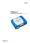
CANblue/VCI
CONTENTS OF DELIVERY
CANblue module and user’s manual
CAN driver VCI for Windows 2000, XP
Simple CAN tool "miniMon"
Intelligent CAN Module with Bluetooth Interface
ORDER NUMBER
1.01.0125.00000
The CANblue/VCI is a CAN module that is connected to the PC
wirelessly via Bluetooth. It is ideal for servicing and accessing CAN
systems that are otherwise difficult to access.
Depending on the space limitations, the maximum distance between the CANblue and the PC/notebook can be up to 100 m.
Because it is supported by the VCI CAN driver, the CANblue/VCI can
be operated with all IXXAT tools and with customer-specified programs. In addition, wireless access to CAN systems via Bluetooth
can also be easily achieved with existing VCI-based application programs and tools.
TECHNICAL DATA
Bluetooth interface Bluetooth specification V2.0, Class 1 / +16,9 dBm
(49 mW), 100m
Microcontroller
Infineon C161U, 36 MHz
Memory extension 256k Flash, 128k RAM
CAN controller
1 x SJA1000
CAN bus interface ISO/IS 11898-2 (High Speed) and ISO/IS11898-3
(Low-Speed), switchable, Sub D9 plug according
to DS102, galvanic decoupled
Power supply
9-30 V DC, 2.5 W
Housing
Stable metal housing
Temperature range 0 ºC to +55 ºC
Certification
CE
Size
88 x 72 x 35 mm
28
CANblue/VCI