1
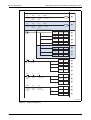
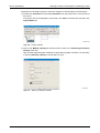
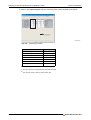
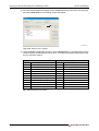
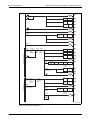
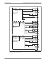
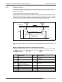
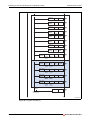
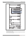
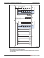
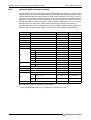
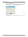
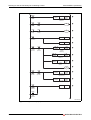
FX2N-1PG-E positioning
Learning to Use the FX Familiy for Positioning Control
Although the following ladder program is not very complicated, it is important to establish good
programming practice by paying attention to the order with which the PLC writes and reads to
the buffer memory of the FX 2N -1PG-E. Before writing the Operation command (START
command) to the module’s BFM from the PLC, several settings must be established such as
Target addresses 1 & 2, Operation speeds 1 & 2, and various settings such as the bias speed,
maximum speed, and the acceleration/deceleration time.
The most critical part of the program is the section where the operation commands are enabled
by writing bits M0 to M15 to BFM#25. When the positioning START command turns ON, the
operation begins with the specified settings.
The ladder program example on the following page can be programmed with an FX2N(C) or
FX3U(C) PLC and does not require an actuator (i.e., servo system) for testing. The following
inputs are used in the program:
Inputs
X000
Error reset
X001
STOP command
X002
Forward rotation limit
X003
Reverse rotation limit
X007
2-speed positioning START command
Tab. 4-17: Used inputs
FX Positioning Control Systems
4 - 39