1
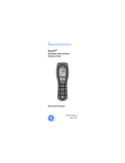
GE
Measurement & Control
Moisture
HygroTrac
Instruction Manual
99 Washington Street
Melrose, MA 02176
Phone 781-665-1400
Toll Free 1-800-517-8431
Visit us at www.TestEquipmentDepot.com
INS9000 Rev. D
June 2012
GE
Measurement & Control Solutions
Moisture
HygroTrac
Moisture Transmitter
Instruction Manual
INS9000 Rev. D
June 2012
INS9000 Rev. D
June 2012
[no content intended for this page - proceed to next page]
ii
Contents
1.
2.
3.
4.
5.
6.
7.
Introduction . . . . . . . . . . . . . . . . . . . . . . . . . . . . . . . . . . . . . . . . . . . . . . . . . . . . 1
System Components . . . . . . . . . . . . . . . . . . . . . . . . . . . . . . . . . . . . . . . . . . . . . 1
HygroTrac Applications . . . . . . . . . . . . . . . . . . . . . . . . . . . . . . . . . . . . . . . . . . 3
3.1
Permanent Installations . . . . . . . . . . . . . . . . . . . . . . . . . . . . . . . . . . . . . 3
3.2
Temporary Installations . . . . . . . . . . . . . . . . . . . . . . . . . . . . . . . . . . . . . 3
Installation . . . . . . . . . . . . . . . . . . . . . . . . . . . . . . . . . . . . . . . . . . . . . . . . . . . . . 3
4.1
Wireless Sensors . . . . . . . . . . . . . . . . . . . . . . . . . . . . . . . . . . . . . . . . . . 4
4.2
Data Acquisition Gateway . . . . . . . . . . . . . . . . . . . . . . . . . . . . . . . . . . . 6
4.3
Gateway Activation and Site Creation. . . . . . . . . . . . . . . . . . . . . . . . . . 6
4.4
Gateway Installation Guidelines . . . . . . . . . . . . . . . . . . . . . . . . . . . . . . 7
4.4aLocation Preparation . . . . . . . . . . . . . . . . . . . . . . . . . . . . . . . . . . . . . . 7
4.4bPower . . . . . . . . . . . . . . . . . . . . . . . . . . . . . . . . . . . . . . . . . . . . . . . . . 7
4.4cAntenna . . . . . . . . . . . . . . . . . . . . . . . . . . . . . . . . . . . . . . . . . . . . . . . . 7
4.4dLocation and Mounting . . . . . . . . . . . . . . . . . . . . . . . . . . . . . . . . . . . . 7
4.4eRear Panel LEDs . . . . . . . . . . . . . . . . . . . . . . . . . . . . . . . . . . . . . . . . . 8
4.4fAccessing Gateway Configuration Menu . . . . . . . . . . . . . . . . . . . . . . 9
4.4gUsing Ethernet Port to Access Configuration Menu. . . . . . . . . . . . . . 9
4.4hUsing the RS-232 Port to Access the Configuration Menu . . . . . . . 12
4.5
Connecting the Gateway to the Internet . . . . . . . . . . . . . . . . . . . . . . . 16
4.5aConnecting the Gateway to an Ethernet LAN. . . . . . . . . . . . . . . . . . 16
4.5bConnecting the Gateway Using Proxy Servers . . . . . . . . . . . . . . . . . 17
4.5cConnecting the Gateway Using a Modem. . . . . . . . . . . . . . . . . . . . . 17
4.6
Secure Digital (SD) Card. . . . . . . . . . . . . . . . . . . . . . . . . . . . . . . . . . . 19
Operation . . . . . . . . . . . . . . . . . . . . . . . . . . . . . . . . . . . . . . . . . . . . . . . . . . . . . 21
5.1
Web Data Service. . . . . . . . . . . . . . . . . . . . . . . . . . . . . . . . . . . . . . . . . 21
5.2
Viewing the Data . . . . . . . . . . . . . . . . . . . . . . . . . . . . . . . . . . . . . . . . . 22
Troubleshooting. . . . . . . . . . . . . . . . . . . . . . . . . . . . . . . . . . . . . . . . . . . . . . . . 23
Technical Specifications . . . . . . . . . . . . . . . . . . . . . . . . . . . . . . . . . . . . . . . . . 25
7.1
Wireless Sensor . . . . . . . . . . . . . . . . . . . . . . . . . . . . . . . . . . . . . . . . . . 25
7.2
%RH/Temperature Sensor . . . . . . . . . . . . . . . . . . . . . . . . . . . . . . . . . . 25
7.3
Moisture Sensor . . . . . . . . . . . . . . . . . . . . . . . . . . . . . . . . . . . . . . . . . . 25
7.4
Data Acquisition Gateway . . . . . . . . . . . . . . . . . . . . . . . . . . . . . . . . . . 26
7.5
Certification . . . . . . . . . . . . . . . . . . . . . . . . . . . . . . . . . . . . . . . . . . . . . 26
HygroTrac Instruction Manual
iii
Contents
iv
HygroTrac Instruction Manual
1.
Introduction
The Protimeter HygroTrac is a simple and cost effective system for remotely
monitoring moisture and temperature levels in buildings. The Protimeter
HygroTrac system measures and logs parameters such as the following:
•
•
•
•
•
GPP or g/kg
dew point temperature
relative humidity
air temperature
% moisture in wood
To set up the system, small HygroTrac wireless sensors are placed in the building.
Sensor readings are transmitted to a Data Acquisition Gateway, which is connected
to a dedicated and secure web server via either an Ethernet or telephone line
connection.
2.
System Components
The Protimeter HygroTrac kit comprises a carry case containing the components
detailed in Table 1 below. Figure 1 on the next page shows a typical BLD9000 kit.
Table 1: Protimeter HygroTrac Kit (BLD9000)
Description
Hard Carry Case with Custom Foam Insert
Data Acquisition Gateway*
Detachable Antenna w/RP-SMA connector
10 Wireless Sensors w/Lithium Batteries*
20 Conductive Mounting Screws
3.3v Power Supply
Ethernet Cable (RJ 45)
Telephone Cable (RJ 11)
Instruction Manual
*Additional sensors (BLD9050) and gateways (BLD9010) are available. For
European use, append “-EU” to the part numbers.
HygroTrac Instruction Manual
1
2.
System Components (cont.)
Figure 1: BLD9000 Kit
2
HygroTrac Instruction Manual
3.
HygroTrac Applications
3.1
Permanent Installations
The Protimeter HygroTrac system provides warnings of potential moisture-related
problems that can lead to property damage or health risks. This makes it ideal for
locations such as:
• heritage and historic buildings
• museums
• food storage
• apartment buildings
3.2
Temporary Installations
The Protimeter HygroTrac system can be used in restoration projects to reduce
costly regular visits to take moisture and humidity measurements when drying a
building after water damage. HygroTrac may be used to:
• automatically produce detailed professional reports
• get output readings from dehumidifiers
• provide early warnings of targets reached and potential problems through
e-mail alerts and cellular text messages
4.
Installation
A complete installation of your Protimeter HygroTrac system includes the wireless
sensors, the data acquisition gateway and website access.
IMPORTANT: The external power supply included in your HygroTrac BLD9000 kit
is fitted with an AC plug suitable for the country of destination. If
you require a different plug, please contact GE Measurement &
Control for assistance.
IMPORTANT: See the Declaration of Conformity at the end of this manual for
HygroTrac certification information.
HygroTrac Instruction Manual
3
4.1
Wireless Sensors
A photograph of a HygroTrac wireless sensor is shown
at the right. To install your wireless sensors, complete
the following steps:
1.
To help determine the best locations for the
sensors, use a standard moisture meter such as the
Protimeter Surveymaster to establish the existing
moisture conditions within the building.
2.
Select up to 600 sensor locations that are within
150 ft (50 m) of the planned location of the data
acquisition gateway.
Note: The maximum sensor transmission distance
varies with the building construction materials. Also, if more than 600
sensors are required, additional gateways will be needed. You may also
need additional gateways if your sensors are out of the sensor RF
transmission range due to distance or building construction materials.
CAUTION!
3.
If it becomes necessary to replace a sensor battery, use only a
LISUN #ER14505 lithium battery and be sure to install it with the
correct polarity. Use of any other battery or installation of the
battery with the incorrect polarity will void your sensor
warranty.
When mounting the sensors, observe the following precautions:
a. If you use a powered screwdriver, be careful not to overtighten the screws.
The screws should be just tight enough to ensure good contact between the
material and the sensor.
b. Avoid placing sensors in locations where they could be stepped on or in
locations where they might interfere with working machinery.
c. Do not mount sensors in areas where water could enter the electronic
components.
4
HygroTrac Instruction Manual
4.1 Wireless Sensors (cont.)
4.
Fix each HygroTrac wireless sensor at its chosen
location using two of the supplied conductive
mounting screws. As the mounting screws are also
the terminals for the moisture sensor, the
HygroTrac moisture reading is taken at the depth
of the screw in the material. For measurements
deeper in the material, you can substitute longer
screws obtained from a local supplier. However,
the screws must be made from stainless steel. The
photograph at the right shows a sensor mounted to
the wall above a doorway.
IMPORTANT: You must be sure to use a spring washer
with each mounting screw to maintain
the integrity of the connection, as the material expands and contracts
with moisture changes.
5.
Record the ID number and location of all installed sensors. The sensors have
bar-coded ID numbers for use with bar-code readers when installing large
numbers of sensors (see photograph on previous page).
HygroTrac Instruction Manual
5
4.2
Data Acquisition Gateway
To install your Data Acquisition Gateway, refer to Figure 2 below and proceed to
the instructions in the next section.
Antenna
Phone Line Port
SD Card Slot
RS232 Port
LAN Port
Power Input
Figure 2: Data Acquisition Gateway - Rear Panel
4.3
Gateway Activation and Site Creation
A gateway sends all the data it collects to the HygroTrac Database Server (HDS).
Users can then access this data at www.gehygrotrac.com (the detailed
instructions in the GE HygroTrac Web Site User’s Guide are provided on the site).
To store and access data, users must:
1. Activate the gateway and assign it to a user-created “site”.
2.
Register as a subscriber.
3.
Create sites by logging into your account and providing information that
describes the site to be monitored (customer name, address, email, etc.).
4. Assign one or more gateways to that site.
Note: When sensors send data through a gateway assigned to a site, those sensors
are automatically assigned to that site as well.
Record the gateway ID which is on the ID label located on the bottom of the
gateway. You will need this ID in order to activate your gateway at
www.gehygrotrac.com.
6
HygroTrac Instruction Manual
4.4
4.4a
Gateway Installation Guidelines
Location Preparation
When planning your installation, remember that the gateway requires an AC power
source and either a LAN or modem Internet connection. Also, position the gateway
as centrally as possible to the planned sensor locations.
4.4b
Power
The gateway requires 3.3 VDC, provided by the supplied AC adapter. Connect the
adapter to an AC power source and plug the jack into the “3.3VDC” receptacle on
the gateway rear panel. When power is active, the PWR LED will be on.
4.4c
Antenna
The antenna supplied with your gateway connects to the “Antenna” connector on
the gateway rear panel. It should be screwed on finger tight. The antenna is
designed to swivel in all directions and must be pointed skyward, or vertically
oriented, for best wireless performance.
4.4d
Location and Mounting
The gateway can either be wall mounted using the built in teardrop-shaped
mounting holes on the bottom of the case (screws not supplied) or it can be placed
on any horizontal surface. In either case, be sure the antenna is pointed skyward.
For best system wireless coverage, locate the gateway central to where the sensors
are to be installed. Do not locate the gateway close to large metal obstructions such
as filing cabinets or refrigerators.
HygroTrac Instruction Manual
7
4.4e
Rear Panel LEDs
The gateway rear panel, shown in Figure 3 below, contains several LEDs which
provide useful information on the status of the gateway.
Figure 3: Data Acquisition Gateway - Rear Panel LED Detail
The LEDs indicate the following information:
Wireless
• TX LED – consistent rapid flashing indicates normal transmitter operation.
• RX LED – flashes briefly while the gateway is receiving data over the wireless
link. The activity of this LED depends on the number of sensors in your system
and the sensor reporting interval.
• Status LED – lit when gateway is communicating normally with the OmniSense
Database Server (ODS).
Modem
• Link LED – flashes to indicate the modem is attempting to dial out; steady light
indicates the modem is connected to the remote modem
• Act LED – when lit, indicates the gateway has successfully logged in to your
ISP; flashes to indicate the sending and receiving of packets
LAN
• Speed LED – always off, indicating 10 Mb/s link speed
• Link LED – Ethernet link is active; flashes to indicate the transmission or
receipt of packets
• PWR – when lit, indicates power is on
8
HygroTrac Instruction Manual
4.4f
Accessing Gateway Configuration Menu
Note: For LAN connections, no configuration changes are usually necessary. For
modem connections, ISP login, password, and phone number are necessary.
To change the gateway configuration, users must enter the configuration menu. You
can access this menu via either the Ethernet port connection or the RS-232 port
connection, using a standard RS232 cable with DB-9 connectors (not supplied).
Either connection provides access to the same menu settings.
4.4g
Using Ethernet Port to Access Configuration Menu
Use the following steps to access the configuration menu via the LAN connection:
1.
Disable and disconnect ALL network connections on your laptop/PC except
for the LAN connection, and then reboot your PC so that the LAN connection
will use an Auto Assigned IP Address.
2.
Connect the gateway to your laptop/PC using the supplied Ethernet cable.
3. Apply power to the gateway, and verify that the LAN Link LED is lit and/or
flashes.
Note: If the LAN Link LED does not go on and/or flash, you will need to use an
Ethernet crossover adapter or an Ethernet Hub.
4.
Wait for ~30 seconds while the PC assigns itself an Auto IP address.
5.
On your PC, verify that it has assigned itself the correct Auto IP address using
“Start>Run” to execute the command “cmd /K ipconfig” as shown below.
Click OK.
HygroTrac Instruction Manual
9
4.4 Data Acquisition Gateway (cont.)
6.
The windows IP configuration window will open. Note that any
169.254.xxx.xxx address is acceptable and your address need not exactly
match the sample address shown below.
7.
On your PC, connect to the gateway configuration menu using Start>Run to
execute the command telnet 169.254.1.1 9999 and click OK, as shown below.
You should see a new window similar to the one shown below.
10
HygroTrac Instruction Manual
4.4 Data Acquisition Gateway (cont.)
Note: If this command fails, then it is likely your PC is not using an auto assigned
IP address. Make sure you that have followed the instructions in Step 1 on
page 9.
8.
Press the spacebar to access the configuration menu and to view the current
gateway settings. You should see the menu shown below.
9.
You can then modify individual settings by selecting the desired menu item.
Note: Be sure to save your changes; saving changes forces a reboot which will
disconnect your telnet session from the gateway.
HygroTrac Instruction Manual
11
4.4h
Using the RS-232 Port to Access the Configuration Menu
Complete the following steps to access the configuration menu via the
RS-232 port connection.
IMPORTANT: Be sure the gateway is unplugged from the power source.
1.
Connect the gateway RS-232 port to your PC’s COM port (usually, but not
always, designated “COM1”) using a serial cable (not supplied).
2.
On your PC start a HyperTerminal window (shown below) using Start>Run to
execute the command hypertrm. Click OK.
3. At the prompt, enter a name (see below) for the new connection and click OK.
12
HygroTrac Instruction Manual
4.4h Using the RS-232 Port to Access the Configuration Menu
(cont.)
4.
You will then be prompted to select the gateway connection (see below);
usually the connection is through the COM1 port, but it will vary from PC to
PC, and in some cases may be through a serial adapter on a USB port. Select
the appropriate COM port name and click OK.
5.
Follow prompts to enter the COM port settings. Configure the COM port with
the following settings and click OK.
•
•
•
•
•
Bits per second: 57600
Data Bits: 8
Parity: None
Stop bits: 1
Flow control: None
HygroTrac Instruction Manual
13
4.4h Using the RS-232 Port to Access the Configuration Menu
(cont.)
6.
You are now ready to power on the gateway. Power on the gateway and your
HyperTerminal window should resemble the screen shown below. If you have
problems, be sure that the HyperTerminal window is the currently selected
window on your desktop and that you do not currently have any text selected in
the HyperTerminal window.
14
HygroTrac Instruction Manual
4.4h Using RS-232 Port to Access Configuration Menu (cont.)
7.
Press the spacebar within 5 seconds of power-up to access the gateway
configuration menu.
8.
You can now modify individual settings by selecting the desired menu item.
Remember to save your changes.
HygroTrac Instruction Manual
15
4.5
Connecting the Gateway to the Internet
If a LAN connection is present, the gateway will automatically use it. If the LAN
connection is inactive, the gateway will attempt to dial out until it reaches the
maximum number of dial retries. Note that if you have an active LAN connection,
but you want the gateway to use the MODEM connection, you must change the
gateway settings from “Auto Detect Connection” to “Use MODEM Connection”.
4.5a
Connecting the Gateway to an Ethernet LAN
Using the supplied Ethernet cable, connect the gateway’s “LAN” port to an
available and active data port on your LAN network. Power on the gateway, and the
Link LED should come on within 1-2 seconds. If it does not, see the troubleshooting
chart on page 23.
1.
Configuring the LAN Connection
The gateway is shipped from the factory to plug-and-play with most common LAN
environments, but from time to time you may need to change the settings to be
compatible with “non-standard” LAN environments. Some possible LAN
configurations include:
• Setting a non-zero “LAN static IP”, “LAN default gateway IP” and “LAN
subnet mask”
Note: You should use a static IP address only if instructed to do so by your
network administrator.
• Setting the “LAN Static IP” to 000.000.000.000 (this is the factory default),
which forces the gateway to use DHCP to acquire an IP address from your
network’s DHCP server.
Note: If no DHCP server is found, the gateway will default to an auto-assigned IP
address of 169.254.1.1 and will continue to try to get a DHCP assigned
address as well.
16
HygroTrac Instruction Manual
4.5a Connecting the Gateway to an Ethernet LAN (cont.)
2.
Testing the LAN connection
If the Status LED lights up, the LAN connection is working. If the Status LED does
not light up, the LAN connection is not working (see Troubleshooting on page 23).
4.5b
Connecting the Gateway Using Proxy Servers
Some networks, especially large corporate networks, block users from direct access
to the Internet. Instead, users must access the Internet through a proxy server. The
gateway can operate with proxy servers; you must set the gateway’s “Remote
Server IP” to the IP address of the network’s proxy server. If you do not know the
proxy server IP address, contact your network administrator. To set your gateway
back for use in a standard (i.e., no proxy server) network environment, set the
“Remote Server IP” to 69.68.219.155.
4.5c
Connecting the Gateway Using a Modem
You must have a working dialup account in order to use the modem.
1.
Connecting the Gateway to a Phone Jack
Connect the gateway to an active analog telephone jack using the supplied
RJ-11 phone cable or a similar phone cable, as shown below. Residential phone
lines are typically analog, while office lines are digital. In an office you should use
a phone line that can support a fax/modem.
Note: The modem interface is surge protected by a non-replaceable non-resetting
slow-blow fuse. If you use a phone line that experiences frequent surges or
lightning strikes, you should put a surge protector in line with the gateway
to protect the modem from damage.
HygroTrac Instruction Manual
17
4.5c Connecting the Gateway Using a Modem (cont.)
2.
Configuring Dialup Information
The gateway requires your Internet Service Provider (ISP) phone number, user
name, and password. You must set these parameters using the New Customer
Registration menu. In most cases, one ISP account can support many gateways and,
in the event your ISP only allows a single login at a time, the gateway will continue
to attempt to login until it reaches the maximum number of retries.
3.
Other Dialup Settings
In most office environments, you will need to dial “9” for an outside line, in which
case you should change the dialup number on the configuration menu to include a
dialing prefix of “9,”. For example:
“Set dialup number(9,18666633679)”
Be sure to include the comma, as it instructs the modem to pause before dialing the
next number, and the pause is required to wait for a dial tone from the outside line.
You can also configure the time between server connection attempts and the
maximum number of dialup retries used during a connection attempt. By limiting
the number of dialup retries, you can prevent the modem from monopolizing the
phone line in the event your ISP is not responding.
The gateway configuration menu also has a configuration option to allow you to
specify a “Modem Custom AT command string”. This string is used only to permit
operation of the modem outside of North America.
4.
Testing Your Modem Connection
First, power up the gateway. If the LAN cable is disconnected or if you have
manually configured the gateway to the “Use MODEM Connection” option, the
gateway will always attempt to dial up the configured ISP such that you can get
immediate confirmation at the time of installation that the modem connection is
working. If the Status LED lights up, and you must watch it carefully as in most
cases it will only stay on for a few seconds, the modem connection is working. See
the section Troubleshooting (page 23) if you do not see the Status LED come on.
18
HygroTrac Instruction Manual
4.6
Secure Digital (SD) Card
The preferred mode of Protimeter HygroTrac operation is through one of the direct
Internet connections. Direct connection permits immediate access to any automated
warnings that may be generated by the system. However, anytime an Internet
connection is not active, the gateway will store data to either the internal flash
memory or the optional Secure Digital (SD) Card if it is present. (You can then
upload this data to the HygroTrac web site by bringing the gateway to a location
that can provide access to your Internet account.)
To set up your HygroTrac system with an SD card:
1.
Purchase an SD card from a local supplier.
Note: A 128 MB SD card will support 10 sensors, reporting every five minutes for
728 days.
2.
Use a computer with an SD card reader to format the new SD card with an MS
Windows FAT file system.
3.
Insert the SD card into the slot on the back of the data acquisition gateway (see
below).
CAUTION!
4.
Use only the GE Measurement & Control power supply provided
with your HygroTrac kit. The use of non-factory power supplies
may damage the equipment and will void your warranty.
Connect one end of the power supply to your data acquisition gateway (see the
photograph on page 17), and plug the other end into a suitable AC outlet. As
the gateway does not have an ON/OFF switch, connection and plugging in will
immediately power up the gateway.
HygroTrac Instruction Manual
19
4.6 Secure Digital (SD) Card (cont.)
5.
To upload your SD card data to the HygroTrac web site, bring the gateway to a
location where a connection to your Ethernet/dial-up Internet account can be
made. Upload time depends on the amount of data, but typically takes a few
minutes.
Note: The gateway includes onboard flash data storage that is sufficient for one
year of data, with ten sensors each reporting every hour. To upload data
from the internal flash storage, use Step 5 above. GE recommends the use of
an SD Card only if your data storage needs exceed the capacity of the
onboard flash storage.
20
HygroTrac Instruction Manual
5.
Operation
As soon as the Protimeter HygroTrac system is installed and powered up, as
described in the previous section, it begins collecting data. In order to access this
data, follow the instructions in this section.
5.1
Web Data Service
Note: Please refer to the GE HygroTrac Web Site User’s Manual for detailed
information on setting up the web site.
The HygroTrac data is stored on a dedicated and secure web server. To access your
data, complete the following steps:
Note: There is a monthly fee for the HygroTrac service account.
1.
Using your existing internet connection, go to the following URL:
2.
Choose one of the following options:
a. If you already have an account, simply log in.
b. If you do not already have an account, create a new user account and accept
the terms and conditions.
c. View the online “Web Site User Guide” for any required help.
3.
Follow the online instructions to view your data.
HygroTrac Instruction Manual
21
5.2
Viewing the Data
After you access your HygroTrac account, the following data is available for each
data point from each sensor, by sensor ID and description:
• Time and date
• Temperature
• Relative Humidity
• Wood Moisture Equivalent (%WME)
• Grains per Pound (GPP) or g/kg
• Dewpoint temperature (°C or °F)
From your HygroTrac account, you can perform the following functions:
• Name the individual sensors to indicate their locations
• View and graph near-live data
• View dewpoint, GPP, temperature, % RH, and % WME data
• Set alarms and thresholds that automatically send e-mails or mobile phone text
messages
• Produce automatically generated reports
• Set up multiple users with different access levels
• Download data in a text file format for importing into a spreadsheet and other
applications
22
HygroTrac Instruction Manual
6.
Troubleshooting
Table 2 below describes possible problems and their solutions.
Table 2: Troubleshooting the LAN/Ethernet Connection
Problem
Cause
Solution
LAN Link LED
is on, but Status
LED never
comes on
The LAN connection the Verify the LAN port you are using
Gateway is using does not can access the Internet.
have Internet access
because Internet
connection is down or
does not exist.
The LAN connection the See page 17 for operating with a
Gateway is using does not proxy server.
have direct Internet
access because network
uses a proxy server.
LAN Link LED The LAN Ethernet port
does not come you are using is not
on
active.
Make sure the Ethernet jack you are
using is active; check with another
computer or laptop.
The Ethernet cable is not Check the Ethernet cable
plugged in.
connections and make sure they
“click” when the plugs are pushed in.
The LAN Ethernet port
you are using is
configured as a client.
Use an Ethernet crossover adapter.
The Ethernet cable is bad. Replace the Ethernet cable.
Status LED is
Gateway out of range of
ON, but when I sensors.
log on to the
website, I do not
see my data
Move gateway closer to sensors.
Not all of my
sensors are
Active on the
website
Relocate gateway closer to sensors
or add additional gateway(s) to
expand wireless coverage.
Gateway out of range of
sensors.
HygroTrac Instruction Manual
23
Table 2: Troubleshooting the LAN/Ethernet Connection (cont.)
Problem
Cause
Solution
MODEM Link
LED goes
solidly on, but
Act LED never
flashes
Bad username and/or
password
Verify username and password are
correct.
MODEM Link No dial tone
Verify phone line has dial tone
LED goes solid Bad dialup phone number Verify dialup phone number is
correct
Missing DSL filter
24
Assuming your phone line is used
for DSL service, add DSL filter to
the line.
HygroTrac Instruction Manual
7.
7.1
Technical Specifications
Wireless Sensor
Transmission Distance*: 150 ft (50 m) nominal
Transmission Frequency: 902.2 - 907.8 MHz;
868.2, 868.4, 869 MHz (EU)
Size (l x w x h): 2.25 x 1.5 x 2.25 in. (60 x 30 x 60 mm)
Weight: 2.42 oz (68 g)
*Transmission distance varies with many factors, including the presence of
obstacles such as concrete walls and interference from other electronic equipment.
7.2
%RH/Temperature Sensor
Range: 0 to 100% (non-condensing)
Accuracy: 10 to 90% ±2.5%
Temperature Range: -40 to 185°F (-40 to 85°C)
Temperature Accuracy: ±1°F (±0.5°C) at 77°F (25°C)
Battery Life: 15 years nominal, when reporting hourly
7.3
Moisture Sensor
Resistance: pin type
Range: 8 to 40%
Accuracy: ±1% in wood, 10 to 25% subject to adjustments for
species and temperature
Calibration Temperature: 68°F (20°C)
HygroTrac Instruction Manual
25
7.4
Data Acquisition Gateway
Maximum Inputs: 600 sensors
Data Transmission: to secure Internet via 10 Mb/s Ethernet output or
dial on-demand telephone modem
Onboard Data Storage: approximately 1 year of data
with 10 sensors each reporting hourly
Additional Data Storage: up to 2 GB on SD card (not supplied)
Size (l x w x h): 7.5 x 4.9 x 1.6 in. (190 x 125 x 40 mm)
Weight: 10.8 oz (305 g)
Power Input: 3.3 VDC external power supply (included)
7.5
Certification
See the Declaration of Conformity at the end of this manual.
The information contained in this manual is given in good faith. As the method of use of
the instrument (and its accessories) and the interpretation of the readings are beyond
the control of the manufacturers, they cannot accept responsibility for any loss,
consequential or otherwise, resulting from its use.
26
HygroTrac Instruction Manual
GE
Sensing
DECLARATION
OF
CONFORMITY
DOC-0039, Rev. A
We,
GE Sensing
1100 Technology Park Drive
Billerica, MA 01821
USA
declare under our sole responsibility that the
Protimeter HygroTrac™ Remote Wireless Environmental Monitoring System
to which this declaration relates, is in conformity with the following standards:
For US and Canada Models Only
• FCC Part 15
This Product Contains Transmitter Module FCC ID: RY20002.
This equipment complies with Parts 15 of the Federal Communications Commission (FCC)
rules for the United States. Operation is subject to the following two conditions: (1) this
device may not cause interference, and (2) this device must accept any interference,
including interference that may cause undesired operation of the device.
The equipment has been tested and found to comply with part 15 of the FCC rules. These
limits are designed to provide reasonable protection against harmful interference in a
residential installation. This equipment generates, uses and can radiate radio frequency
energy and, if not installed and used in accordance with the instructions, may cause
harmful interference to radio communications. However, there is no guarantee that
interference will not occur in a particular installation. If this equipment does cause
harmful interference to radio or television reception, which can be determined by turning
the equipment off and on, the user is encouraged to try and correct the interference by
one or more of the following measures:
• Reorient or relocate the receiving antenna.
• Increase the separation between the equipment and receiver.
• Connect the equipment into an outlet or on a circuit different from that to which the
receiver is connected.
• Consult the dealer or an experienced radio/TV technician for help.
FCC Part 15 Warning: Changes or modifications to this unit not expressly approved by
the party responsible for compliance could void the user's authority to operate the
equipment.
• Industry Canada (IC)
This Product Contains Transmitter Module IC ID:6474A-0002.
This digital apparatus does not exceed the Class B limits for radio noise emissions from
digital apparatus set out in the interference causing equipment standard entitled Digital
Apparatus, ICES-003 of Industry Canada. This device complies with Canadian RSS-210
regulations.
NOTICE: The Industry Canada (IC) label identifies certified equipment. The Department
does not guarantee the equipment will operate to the user’s satisfaction.
Page 1 of 2