1
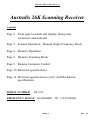
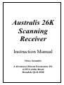
Australis 26K
Scanning
Receiver
Instruction Manual
Titley Scientific
A division of Elexon Electronics P/L
6/253 Leitchs Road
Brendale QLD 4500
Australis 26K Scanning Receiver
Australis 26K Scanning Receiver
Contents
Page 2 Front panel controls and display, Rear panel
connectors and indicator
Page 3 Scanner Operation - Manual Single Frequency Mode
Page 4 Memory Operation
Page 6 Memory Scanning Mode
Page 9 Remote Computer Control
Page 10 Electrical specifications
Page 11 Electrical specifications (cont.) and Mechanical
specifications
SERIAL NUMBER
SR 1234
FREQUENCY RANGE 149.0000MHz TO 152.9999MHz
Page 1
Rev. M
Australis 26K Scanning Receiver
Front Panel Controls and Display
Volume Control
Conventional knob operated potentiometer with On/Off switch. Off is fully
CCW position.
Gain Control
Knob operated potentiometer. Gain is maximum when the control is fully CW.
The minimum gain reduction is 50 dB.
Keys
16 luminous membrane keys are incorporated in the front panel. 0-9, Recall,
Save, Scan, Up and Down Fine Tuning, and Light.
Antenna Input
Standard type BNC connector.
Headphone
Two 3.5mm mono phone jacks. The jack marked with a crossed line attenuates
the loud speaker when the phone jack is plugged.
Display
A graphic type liquid crystal display approximately 16 x 54 mm is used to
display all frequency, signal strength, battery capacity and mode data. It has
LED back lighting which can be switched on for night viewing.
Rear Panel Connectors and Indicator
Battery Charger/Power
A 2.5mm DC socket is provided for connecting a plug pack or other charger or
external power supply. The centre pin is the positive terminal. If operation off a
permanent 12 volt external supply is required, then you must remove the
bottom (black) cover and disconnect the battery plug from its matching socket.
This will allow for constant external operation.
Charge Indicator
The RED LED on the rear panel lights to indicate the batteries are being
charged at the fast charge rate (approx. 4 hours from flat). Once the LED
switches off, batteries continue to be charged at the trickle rate.
Data Connector
Data can be transferred between the scanner and a host computer using a
special interface cable available from Titley Electronics.
Page 2
Rev. M
Australis 26K Scanning Receiver
SCANNER OPERATION
Audible Indication of Key Press
When any key is pressed, a short beep is heard in the loudspeaker and headphones. The sound level is
independent of the receiver volume control setting.
Light
The Light key toggles the display back light On/Off. To save battery life the light automatically switches off
after ten minutes.
Headphone Outputs
Two 3.5 mm mono phone jacks are provided. One switches off the loudspeaker when the headphones are
plugged in. The other leaves the loudspeaker on.
Field Strength Meter
This is displayed as a bar graph 0 - 10, and gives a good indication of direction.
Battery Indicator
If the battery voltage is good, then the message ‘OK’ is displayed in the lower left window of the display.
Once the battery falls to a marginal voltage for correct operation, the message ‘LO’ is displayed in place of
the ‘OK’ message and a beep from the speaker will heard every 5 seconds to alert you to this low battery
condition. Operation in this low battery condition can not guarantee that the scanner will meet the
specifications.
OPERATING MODES
MANUAL SINGLE FREQUENCY MODE
Manual single frequency mode is always selected at power on of the receiver, regardless of what mode the
scanner was in when the power was turned off. On power on, the frequency displayed and being tuned is the
last frequency that was displayed on the LCD in the manual single frequency mode. The message
‘MANUAL’ appears in the upper left corner window of the LCD display when the scanner is in manual single
frequency mode.
In the manual single frequency mode the receiver is continuously tuned to the frequency indicated in the
display window. To change the frequency, the new seven digit frequency is entered using the numeric keys.
The first frequency digit is always "1", and does not need to be entered. Six digits must always be entered to
set the frequency.
When the first key is pressed the corresponding number is displayed in the second from left (tens of MHz)
display position. The first digit entered (the 10MHz digit) must be valid for the range the scanner has been
optimised for, entering a digit other than the correct range value will cause the unit to ignore the digit and
issue a beep only. The remaining digits are blanked. As the remaining five digits are entered they are
displayed in the appropriate position progressing from left to right. The second digit entered (the MHz digit)
must also be valid for the range the scanner has been optimised for, entering a digit other than the correct
range value will cause the unit to ignore the digit and issue a beep only. When the last digit is entered the radio
will switch to the new frequency. If the full sequence of six digits is not completed or the delay between
successive keys exceeds twenty seconds, the operation is cancelled and the display reverts to show the current
frequency.
Page 3
Rev. M
Australis 26K Scanning Receiver
MANUAL SINGLE FREQUENCY MODE cont.
Thus for example, if the scanner has been optimised for the 149MHz to 152MHz bands, then the first two
digits you enter for the frequency must be between 49 and 52 representing 149.0000MHz to 152.9999MHz
Fine Tuning
The receiver frequency can be fine tuned by pressing the UP ARROW or DOWN ARROW keys. The
fine tuning allows the frequency to be adjusted in 100 Hz steps. If the UP ARROW or DOWN
ARROW fine tune buttons are pressed continuously, then the fine tuning steps at 500 Hz while the UP
ARROW or DOWN ARROW fine tune buttons are held pressed. This allows for locating a frequency
quickly with the fast fine tune function, and then when near the required frequency, single button
presses can set the final frequency in 100 Hz increments. The fine tuning varies approximately 90 steps
per minute.
MEMORY OPERATION
The memory of the scanner is arranged as ten banks of ten memories allowing the user to store up to
one hundred individual frequencies in the memory.
a)
Save Function
The currently displayed frequency can be stored in any of the one hundred memory locations by simply
pressing the Save key. The display then prompts ‘BANK?’. The Bank number that was last selected is
indicated on the display. If a different Bank number is desired, then the new Bank number can be
entered using one of the 0-9 numeric keys. Alternatively, pressing Save again selects the Bank number
currently displayed and moves you on to selecting the required Memory number. The display then
prompts ‘MEM?’. The Bank and Memory numbers that were last selected are indicated in the upper
left window of the display. If a different memory number is desired, then the new Memory number can
be entered using one of the 0-9 numeric keys. Alternatively, pressing Save again selects BOTH the
Bank AND Memory numbers currently displayed in the upper left window of the display.
Once the Save function is complete, a new frequency can be entered as in manual single frequency
mode, with the display clearing the Bank and Memory window at the end of a successful six digit
manual entry sequence. Alternatively the frequency displayed can be fine tuned with the UP ARROW
or DOWN ARROW fine tune keys, with the display clearing the Bank and Memory window on
detecting the first key press of the UP ARROW or DOWN ARROW fine tune keys.
If the full sequence of six digits is not completed or the delay between successive keys exceeds twenty
seconds, the operation is cancelled and the display reverts to show the current frequency.
This is an example to save transmitter frequency 151-0980 MHz into Memory 7 of Bank 1
•
•
•
•
•
•
Program in Transmitter frequency by pressing the buttons 5 , 1 , 0 , 9 , 8 , 0
The LCD should now display ‘151.0980’ as the required frequency
Press SAVE, the LCD now prompts for a BANK number
Press the Bank number in which you want to use, 1
The LCD now prompts for a MEMORY number
Press the Memory number in which you want to use, 7
Page 4
Rev. M
Australis 26K Scanning Receiver
MEMORY OPERATION cont.
a)
Save Function cont.
When scanning within a bank of ten memories, and as an example only six of the 10 memories have
frequencies you wish to scan, you must “lock out” the 4 unused memories so that the scanning only
looks for a signal on the 6 required memories.
To “lock out” these 4 unused memories, you must save a frequency of 0MHz into those memories. The
method to do this is as follows.
This example “locks out” memories 7 , 8 , 9 and 0 on BANK 1. Thus when you scan BANK 1, only the
frequencies in memories 1 , 2 , 3 , 4 , 5 and 6 will be scanned for a signal.
•
•
•
•
•
•
•
From Manual Single Frequency Mode
To “lock out” a memory press the 0 numeric key
The LCD screen will now read ‘---.----’
Press SAVE, the LCD now prompts for a BANK number
Press the Bank number which you want to use , 1
The LCD now prompts for a MEMORY number
Press the first Memory number which you want to “lock out” , 7
Having “locked out” Memory 7 on Bank 1, we now must also lock out the other 3 unused memories in
Bank 1. Repeat the process below until all unused memories are “locked out”
•
•
•
•
Press SAVE, the LCD now prompts for a BANK number
Press SAVE again, as the current Bank number is already Bank 1
The LCD now prompts for a MEMORY number
Press the next Memory number which you want to “lock out” e.g. 8 then 9 then 0
Now when BANK 1 is scanned, only memories 1 through to 6 will be scanned for a signal. To
“unlock” a memory for usage, program a valid frequency, then store that frequency into the required
memory you wish to “unlock”.
b)
Recall Function
A frequency is recalled from memory by pressing the RECALL key. Once recalled from memory, the
frequency can be fine tuned to optimise the signal if required, then saved to the same memory using the
Save function described above. Alternatively, a totally new frequency can be stored into the memory just
recalled if you wish to overwrite the previous value. The Bank and Memory numbers to be recalled, are
selected in the same way as for the Save function, with the Bank and Memory numbers displayed being
those used for the last Save OR Recall function. Pressing RECALL retains the current Bank or Memory
number.
If during the Save or Recall sequence more than twenty seconds elapse without a key entry, the
operation is cancelled, the display clears and it now displays the last frequency that was entered in the
Manual Single Frequency Mode.
Page 5
Rev. M
Australis 26K Scanning Receiver
MEMORY OPERATION cont.
b)
Recall Function cont.
This is an example to recall the frequency programmed into Memory 5 of Bank 1
•
•
•
•
Press RECALL, the LCD now prompts for a BANK number
Press the Bank number in which you want to recall, 1
The LCD now prompts for a MEMORY number
Press the Memory number in which you want to recall, 5
The LCD will display the last frequency stored in Memory 5 of Bank 1. If the LCD displays ‘---.----’ ,
then that memory location has been “locked out” from being scanned. If a memory has been
programmed with ---.---- as a lock out value, then when recalled etc., the audio will be muted from the
speaker. A valid frequency can be input and saved as described in the Save function above.
MEMORY SCANNING MODE
SETTING THE SCAN CHARACTERISTICS
Memory scanning enables the scanner to search for up to a hundred signals, corresponding to the
frequencies stored in ten Banks, each Bank having ten Memories, giving a total of one hundred
Memories. Scanning can occur over one individual Bank of ten Memories, or up to ten Banks of ten
memories.
Within a Bank of ten Memories, the unused Memories can be “locked out” to prevent the scanner
looking for a signal on an unused Memory. NOTE - See the Save function for a detailed description of
“lock out” of unused Memories. Thus the scanner will only look for signals on memories with valid
frequencies programmed, i.e. not “locked out”. If you are unsure about what frequency the Memories
within a Bank are programmed with, use the Recall function to examine each Memory within the Bank
in question.
The receiver is put into the Scan set-up mode by pressing the SCAN key. The display then prompts
‘BANK?’. The Bank numbers currently selected are indicated as two rows of numbers, 1 through to 5,
and 6 through to 0 in the upper right window on the display. As explained before, you can scan from one
Bank of ten Memories, up to ten Banks of ten Memories. When a number is displayed in the upper right
window of the display, it indicates that the associated Bank will be scanned during the Scan procedure.
If the window has NO numbers displayed, this indicates that NO Banks have been selected for scanning.
Pressing a 0-9 Numeric key representing the bank number, will alternate its value from being displayed
or not being displayed.
Thus as Memories within a Bank can be “locked out”, so can unused Banks.
Page 6
Rev. M
Australis 26K Scanning Receiver
MEMORY SCANNING MODE cont.
SETTING THE SCAN CHARACTERISTICS cont.
In the upper left window on the display, there are two rows of messages. The top row indicates the
current setting for the squelch mode of the scanner. The display will either show ‘SQ ON’ or ‘SQ OFF’
The bottom row indicates the current setting for the scan rate and hold mode of the scanner. The display
will show four scan rates ‘FAST’ or ‘FAST + H’, ‘MED.’ or ‘MED. +H’, ‘SLOW’ or ‘SLOW +H’
and ‘XSLOW’ or ‘XSLOW +H’ where the optional ‘+H’ represents the hold mode of scanning
operation.
SQUELCH FUNCTION
SQUELCH is used to control the presence or absence of audio during scanning operation.
Pressing the UP ARROW Fine Tune button, will cause the SQUELCH message to toggle between two
values (‘SQ ON’ or ‘SQ OFF’). Press the key to change the value, press it again to return it to the
previous value.
If SQ OFF is selected, then CONTINOUS audio will be heard during the scanning operation, regardless
of the received signal level on ANY memory frequency !!
If SQ ON is selected, then during scanning if a frequency being received has a signal which is above the
preset level, then audio will be heard from the speaker for this frequency. Thus when scanning
frequencies where the signal is below the preset level, no audio is heard and scanning continues with no
audio until a signal exceeds the preset level and causes audio to be heard once again, but ONLY for the
memory whose signal has exceeded this preset level. ONCE the scanner advances to the next memory,
the audio will be muted again, unless the signal on the next memory is ALSO above the preset level, in
which case audio will also be heard for this memory.
SCAN RATE
SCAN RATE is used to determine how quickly the scanner advances through the selected Banks and
Memories when scanning. There are four scanning rates, these being
FAST
MED. (medium)
SLOW
XSLOW
1.25 seconds per memory
2.5 seconds per memory
5 seconds per memory
10 seconds per memory
Page 7
Rev. M
Australis 26K Scanning Receiver
MEMORY SCANNING MODE cont.
HOLD FUNCTION
HOLD function determines if the scanner steps continuously through its selected Banks and Memories,
or stops (HOLDS) on a frequency whose signal has exceeded the preset level (as explained in the
SQUELCH FUNCTION).
If the HOLD function is selected (as indicated by ‘+H’ on the right hand side of the SCAN RATE value)
then when a signal is received which is above the preset level, the scanner will stop on the current
frequency, and remain there while ever a signal above the preset level is being received.
If HOLD function is selected, then rotating the receiver Gain knob anti-clockwise reduces the
receivers gain, and thus increases the signal level which must be received before it causes the scanner to
HOLD and stop the Scan action, keeping the scanner onto one frequency.
If HOLD function is selected, then rotating the receiver Gain knob clockwise increases the receivers
gain, and thus reduces the signal level which must be received before it causes the scanner to HOLD and
stop the Scan action, keeping the scanner onto one frequency.
If HOLD function is NOT selected, then the scanner will continuously advance through the selected
Banks and Memories at the selected SCAN RATE, regardless of received signal level.
Pressing the DOWN ARROW Fine Tune button, will cause both the SCAN RATE and the HOLD
function to cycle through the possible combinations. NOTE that after every new scan rate selected, the
next DOWN ARROW button press will cause the HOLD function to be selected for the new scan rate.
Pressing the DOWN ARROW once more, moves on to the next scan rate and clears the hold function
for the new scan rate. Thus the DOWN ARROW act as a toggle for both the Scan Rate and the Hold
function for scanning.
STARTING SCANNING
Once the desired Banks for scanning are selected (as displayed by their numbers in the upper right
window of the display), and the Squelch, Scan Rate and Hold functions are as desired, the scanner can
be placed into Scanning by again pressing the SCAN key. The receiver will then begin scanning the
selected Banks, starting with Bank 1 (if selected) and then Banks 2 through to 9 then Bank 0 last (if also
selected).
Within a Bank, scanning starts with Memory 1 (if not “locked out”) and cycles through to Memory 9
then 0 (if also not “locked out”) looking for a signal. While the receiver is scanning the audio signal
heard will depend on the setting of the Squelch function and the signal level received (if Squelch is ON).
While scanning for a signal, the current Bank AND Memory number AND its Frequency are indicated
on the display, with the Memory number being to the right of the ‘SCAN’ message in the lower line of
the upper left window of the display.
When Memory number zero (if not “locked out”) or the highest number valid Memory has been used
and a signal has been received that has NOT exceeded the preset level on that frequency (only if in +H
HOLD mode), the next selected Bank (if more than one bank selected) will be scanned. Thus the scanner
continuously rotates through all the valid Memories in all the selected Banks.
Page 8
Rev. M
Australis 26K Scanning Receiver
MEMORY SCANNING MODE cont.
STARTING SCANNING cont.
While scanning, pressing either the UP ARROW or DOWN ARROW fine tune keys will move the
scanner on the next or previous memory in the scan sequence. Keeping these keys held, will cause the
scanner to continuously move forward or backward through the scan sequence until the keys are
released. Thus you can quickly move on to another memory number within selected banks without
having to wait for the scanner to move through at the selected scan rate to reach the desired new
memory.
MANUAL HOLD FUNCTION
To stop the scanner on a particular memory, so that its stays continuously on that frequency (MANUAL
HOLD), regardless of whether the signal disappears temporarily or not, press the SCAN key to take the
scanner out of memory Scanning mode. The display will show the Bank and Memory numbers, and the
frequency programmed in the memory when Scan action was “HELD”. The Memory number the
scanner has “HELD” on is displayed to the right of the ‘HOLD’ message on the lower line of the top
left window of the display.
To resume scanning once more, press either the UP ARROW or DOWN ARROW keys to move
forward or backwards in the scan sequence and resume scanning, taking the scanner out of “MANUAL
HOLD” mode.
To exit scanning all together and return to the Manual Single Frequency mode, simply press the SCAN
key. You can now use the UP ARROW or DOWN ARROW fine tune keys to manually adjust the
frequency you stopped the scanner on if you wish, or recall any frequency programmed into the
memory.
REMOTE COMPUTER CONTROL
With an appropriate interface cable connected to a serial port on an IBM compatible computer, remote
control of the scanners frequency and monitoring of the received signal level is possible with appropriate
software.
NOTE. - CONNECTION OF THE SCANNER DIRECTLY TO A
SERIAL PORT (WITHOUT THE CORRECT INTERFACE CABLE)
OF AN IBM COMPATIBLE COMPUTER WILL POTENTIALLY
DAMAGE BOTH THE SCANNER AND THE COMPUTER !!!!
NEVER CONNECT THE SCANNER TO A COMPUTER WITHOUT
THE CORRECT INTERFACE CABLE WHICH CONTAINS SIGNAL
LEVEL CONVERSION ELECTRONICS !!!!
The correct interface cable and control software will be available from Titley Electronics
Page 9
Rev. M
Australis 26K Scanning Receiver
ELECTRICAL SPECIFICATIONS
Sensitivity
The sensitivity of this type of receiver is often quoted as the minimum discernible signal level. This is
subjective and not a reliably measurable level. Therefore, the sensitivity characteristic of the receiver is
defined here by specifying the maximum noise figure. This can then be related to the signal to noise ratio for
any given bandwidth.
Receiver Noise Figure
2dB maximum
Sensitivity for 10 dB S+N/N -135 dBm @ 400 Hz BW
Selectivity
-6 dB BW 800-1000 Hz
Intermodulation
> 70 dB rel. to 10 dB S+N/N
Image and Spurious
> 80 dB rel. to 10 dB S+N/N
Gain Control Range
50 dB minimum
( 0.04 uV into 50 Ohms)
-50 dB BW < 5.5 kHz
Nominal Input Impedance 50 Ohms
Frequency Range
Set to any 4 MHz segment in 146- 176 MHz ( 149-153 MHz std. )
Frequency Selection
100 Hz and 500 Hz steps
Frequency Stability
Better than 1 kHz -10 to +60 C
Frequency Memories
10 banks of 10 memories with fine tune offset stored for each frequency
Memory Scanning Rate
Can be set to 1.25 , 2.5 , 5 or 10 Seconds per Channel
Memory Retention
Memory is retained while the receiver is switched off and while battery
packs are changed.
Intermediate Frequency
13.053 MHz
Beat Frequency Oscillator
Set nominally 2 kHz above the selected frequency for lower sideband
reception
Audio Output
250 mW into internal loudspeaker or external load
Battery Supply
9.6 Volt Ni-Cd pack, 8 AA cells or disposable cells
Page 10
Rev. M
Australis 26K Scanning Receiver
ELECTRICAL SPECIFICATIONS cont.
Battery Life
14 hours operation using the standard 1.1 Ah Ni-Cad battery pack.
(Backlight off).
Low Battery Voltage
‘LO’ is displayed on front panel and an audible warning sounds when the
internal regulated supply falls to 9.1 volts
Battery Charging
External dc plug pack or any 13-16 Volt dc source, 750 mA or greater. The
internal constant current charging circuitry operates at 350mA ( 4 hour fast
charge rate) and 50mA (trickle charge rate ). Application of external voltages
greater than 18 volts may cause damage.
Battery Current
Typically 80 mA , normal standby with backlight off.
Backlight Current
50 mA
Signal Strength Resolution Approximately 0.1 dB
650 mSec
Signal Strength Display Hold Time
MECHANICAL / ENVIRONMENTAL SPECIFICATIONS
Size
50 x 145 x 170 mm ( H x W x D )
Weight
approx. 1 KG
Case Construction
Aluminium sheet fabrication with polyester finish
Sealing
The case design minimises the intrusion of dust, dirt or spray. All external joints
are either overlapping or sealed.
Front Panel
Reverse printed polycarbonate panel incorporating a display window and 16
keys.
Circuit Technology
Surface mount on double side plated through FR4 board. Re-flow soldered
(Specifications may alter without notice)
Page 11
Rev. M