1
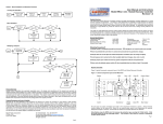
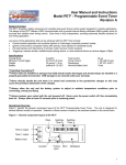
Figure 6 - Menu Navigation and Operation Flowchart
User Manual and Instructions
Model PET2+ - Programmable Event Timer
Revision 1.12
Invoking the Start Menu
Start
Press & Hold
Select PB
Power-up
altimeter
Wait for
chirp
Start Menu
activated
Release
Select PB
System Overview
The PET2+ provides a highly advanced and versatile dual-event timing control system targeted for high power
rocketry. The design of the PET2+ utilizes a RISC microcontroller with a precise internal factory-calibrated 4MHz
system clock for accurate and reliable event timing control. In addition the PET2+ uses a 3-axis “micromachined”
accelerometer to detect specific inertial events during flight. This 3-axis capability allows mission specific timer
orientation in the rocket. Each timer is fully independent, providing extremely flexible solutions for any rocketry
timing application.
Menu Navigation
Start
LED shows
choice
No
Select PB
No
Enter PB
Yes
Just some of the applications that can be achieved with the PET2+ timer include:
· Precise booster separation and sustainer ignition of multi-stage composite powered rockets
· Ignition of secondary composite motors after primary motor ignition for airstarted boosts
· Fail safe backup and redundancy of primary rocket recovery control systems
· Triggering a camera shutter, audible/visual tracking device, or other electrical device at various stages of flight
Yes
Next menu
choice
Take this menu
choice
General Specifications
Arming Mode
Inertial G trigger range
Battery/Power range
Nominal Battery load
Modifying a Setpoint
Start
LED shows
setpoint ID
No
Select PB
Yes
Next setpoint
ID
Inertial/Breakwire
2-5 G’s
6-14 VDC
6-14ma
Dimensions
Output current (sinking)
Continuity current
Weight
1" W x 3.15" L
5A @ 0.5 sec
9µa @ 9V
17 grams
No
Enter PB
Handling Precautions
Always handle in a properly grounded environment. ESD damage is not covered under your warranty.
A
Yes
Never touch/handle the unit when it is armed and connected to live pyrotechnic charges.
Always allow the unit to adjust to ambient temperature prior to arming/flying, and avoid extreme temps.
Chirp/Flash
Setpoint
Never arm the timer and then load your rocket onto the launch rail. Arm the timer once on the rail.
Always prepare your rocket and timer system components with the unit powered off.
No
Select PB
No
Enter PB
Yes
A
Physical Overview
Yes
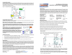
Figure 1 depicts the general component layout of the PET2+ Programmable Event Timer.
Figure 1 - General component layout of the PET2+
Tap in new
value with
Select PB
Battery
LED
MCU
Piezo
Enter PB
Event 2 Output
Select PB
Event 1 Output
Tap Enter
PB when
complete
Product Warranty
Missile Works Corporation has exercised reasonable care in the design and manufacture of this product and warrants the
original purchaser that the PET2+ is free of defects and that it will operate at a satisfactory level of performance for a period of
one year from the original date of purchase. If the system fails to operate as specified, then return the unit (or units) within the
warranty period for repair or replacement (at our discretion). The system must be returned by the original purchaser, and be
free of modification or any other physical damage which renders the system inoperable. Upon repair of replacement of the unit,
Missile Works Corporation will return the unit postage-paid to the original purchaser.
Product Disclaimer and Limit of Liability
Because the use and application of this equipment are beyond our control, the purchaser or user agrees to hold harmless
Missile Works Corporation and their agents from any and all claims, demands, actions, debts, liabilities, judgments, costs, and
attorney fees arising out of, claimed on account of, or in any manner predicated upon loss or damage to property of, or injuries
to or the death of any and all persons arising out of the use this equipment. Due to the nature of electronic devices, and the
application and environments for those devices, the possibility of failure can never be totally ruled out. It is the responsibility of
the purchaser or user of this equipment to properly test and simulate the actual conditions under which the device is intended to
be used to ensure the highest degree of reliability and success.
Missile Works Corporation
PO Box 1725
Lyons, CO 80540
Breakwire Input
Accelerometer
All user input and output connections are made to the compression terminals as shown. These terminals
include: Battery (logic and/or pyro power), Breakwire (for a N/C wire loop or switch), and Event1/Event2 (for
external pyro events or controls). All terminals are marked on the board silkscreen for reference.
Note: Before using the PET2+, familiarize yourself with the location and designation of all the user
connection terminals, pushbutton controls, and with the audible feedback and LED functions. These
functions, operations, and connections are covered in subsequent sections of this manual.
Pg. 1
Tel: 303.823.9222 Fax: 303.823.9777
On the World Wide Web @ www.missileworks.com
Copyright 2000-2010 by Missile Works Corporation.
All rights reserved.
Pg. 8
Setpoint and Operations Matrix
Pre-Flight / In-Flight / Post-Flight Modes of Operation
The PET2+ has several distinct modes throughout the course of its operation during flight. These modes of operation are easily
identified by the function of the piezo and the LED.
Power-up mode
When power is first applied to the unit, it will provide a continuous 2-second chirp to indicate it has been switched on. During
this 2-second chirp the LED will be solid RED.
Accelerometer initialization mode
After the Power-up mode, the unit goes through a 10-second accelerometer initialization start-up delay. The LED will flash
slowly in YELLOW while in this mode. This delay period allows stabilization of the device and establishes the initial orientation
and inertial references.
POST (Power Up Self Test) Verification / Error Chirp Mode
The PET2+ performs several sanity checks after initialization mode based on its current configuration to ensure that the rocket
and timer are oriented properly and within allowable launch angle and calibration limits. If using the Breakwire trigger, this input
is also checked for a proper “closed loop” condition. If the unit detects no problems, no mis-orientation, and no misconfiguration, it will arm both of the event timers and transition immediately into Launch Detect Mode.
If the PET2+ detects an error during Verification Mode it will NOT transition into Launch Detect mode. Instead it will sound an
alarm tone (buzz) and continuously chirp and flash YELLOW with an ERROR CODE to indicate what specific error condition
was detected. DO NOT MISTAKE AN ERROR CODE CONDITION for flight readiness and valid continuity feedback and
inadvertently launch your rocket. The error codes are as follows:
Error Code
1
2
3
4
5
Error Condition
X-axis triggering and off-axis or off-cal limit
Y-axis triggering and off-axis or off-cal limit
Z-axis triggering and off-axis or off-cal limit
Auto-axis detection and no valid axis/orientation detected
Breakwire triggering with initial open circuit
Launch Detect mode
When all previous modes are complete, the unit transitions into launch detect mode. The piezo and the GREEN LED indicate
the continuity status of the Event 1 and Event 2 output terminals every second as follows:
Status Code
1 Long Beep/Flash
1 Short Beep/Flash
2 Short Beeps/Flashes
3 Short Beeps/Flashes
Status Condition
No continuity on Event1 or Event 2 outputs
Continuity on Event 1 output only
Continuity on Event 2 output only
Continuity on both Event 1 and Event 2 outputs
LED Legend:
Timing operation mode
When in Timing Operation mode, the LED flashes fast in RED (≈6Hz). The unit can have one or both timers active at any given
time based upon the triggering and timing configuration. This mode of operation remains active until both of the timers have
completed a timing cycle and the associated output event has been initiated. Once this occurs, the unit transitions into Post
Timing mode.
Post Timing Mode
When in Post Timing Mode, the LED will flash slowly in YELLOW (≈2Hz). The unit will continue in this mode until it is powered
off. Keep in mind that if either timer has been configured in “repeat” mode, the repeat timing cycles are active during this mode.
Programming and Configuration
Accessing the Start Menu
Please refer to the Setpoint and Operations Matrix reference included in this manual when reading and reviewing this section.
Also refer to the Figure 6- Menu Navigation and Operation Flowchart for additional help.
To start the interactive operation of the PET2+, press and hold the SELECT pushbutton while applying power to the unit. Release the pushbutton after you hear a brief chirp from the piezo. You’re now at the Start Menu and displaying the first choice
(SLOW FLASHING RED / Setpoint Menu)
Start Menu Navigation
To scroll to the next available choice in the menu, tap the SELECT pushbutton. To make a choice in this menu, tap the ENTER
pushbutton. (note: a brief chirp acknowledges each button press).
Start Menu Options
All other menus are accessed from the Start Menu. The available options are:
- Timer 1 Setpoint Menu
Provides verification and adjustment of all user setpoints for Timer 1.
- Timer 2 Setpoint Menu
Provides verification and adjustment of all user setpoints for Timer 2.
- Global Setpoints & Diags Menu
Verify/Adjust the PET2+ global setpoints or exercise the PET2+ diagnostic features.
- Escape to Flight Mode
Exit the Start Menu and return to normal flight operations mode.
Timer 1 / Timer 2 / Global Setpoint Menus
All user adjustable setpoints are available from these menus. You can verify all setpoints, and you can adjust all setpoints. The
PET2+ provides 2 independent and identical groups of setpoints for each timer. The Global Setpoints are applied and used by
both timers appropriately. All setpoint values are stored in nonvolatile memory.
Pg. 2
SLOW FLASH
X
FAST FLASH
X
X = LED Color
R = RED / G = GREEN / Y = YELLOW
FLICKER FLASH
X
X
Start Menu
R
Navigate to Timer 1 Setpoint Menu
G
Navigate to Timer 2 Setpoint Menu
Navigate to Global Setpoints and Diagnostics Menu
Y
R
Exit to Flight Mode
G
Timer 1 Setpoint Menu
Range
Default value
R
MEIG Trigger Level
2-5 (G’s)
2
G
SEIG Trigger Level
2-5 (G’s)
3
Y
Inertial Trigger Event
1=MEIG / 2=MECO / 3=SEIG / 4=SECO
2
R
Trigger Integration Time
0.1 - 3.0 seconds (1 to 30)
2
G
Breakwire Function
1=N/A, 2=Exclusive Trigger, 3=Interlock Trigger
1
Y
Timer Interval
1-100 (Time base dependent)
5
R
Time Base
1=Fast (0.1 sec), 2=Slow (1 sec), 3=XSlow (2 sec)
1
G
Output Pulse
0.1 - 3.0 seconds (1 to 30)
5
Y
Timer Operation
1=One-shot, 2=Repeat
1
R
The unit also monitors the accelerometer and/or Breakwire input in order to determine the launch of the rocket. After this event,
the unit transitions into timing operation mode.
SOLID
G
Exit to Start Menu
Timer 2 Setpoint Menu
Range
Default value
R
MEIG Trigger Level
2-5 (G’s)
2
G
SEIG Trigger Level
2-5 (G’s)
3
Y
Inertial Trigger Event
1=MEIG / 2=MECO / 3=SEIG / 4=SECO
2
R
Trigger Integration Time
0.1 - 3.0 seconds (1 to 30)
2
G
Breakwire Function
1=N/A, 2=Exclusive Trigger, 3=Interlock Trigger
1
Y
Timer Interval
1-100 (Time base dependent)
10
R
Time Base
1=Fast (0.1 sec), 2=Slow (1 sec), 3=XSlow (2 sec)
1
G
Output Pulse
0.1 - 3.0 seconds (1 to 30)
5
Timer Operation
1=One-shot, 2=Repeat
1
Y
R
G
Exit to Start Menu
Global Setpoint and Diagnostic Menu
R
Inertial Trigger Axis
G
Y
Range
Default value
1=X Axis, 2=Y Axis, 3=Z Axis, 4=Auto Axis
4
Off Axis/Cal Deviation
1-10 ( 5 Represents ≈ ± 20 degrees)
5
Piezo Tone
1=High Tone, 2=Low Tone
1
R
Output Test Mode
(N/A)
G
Input Test Mode
(N/A)
R
G
Exit to Start Menu
Pg. 7
Figure 5– Mounting Dimensions for the PET2+
Setpoint Menu Navigation and Setpoint Adjustment
To scroll to the next available setpoint choice in the menu, tap the SELECT pushbutton. To choose a setpoint, tap the ENTER
pushbutton. After a setpoint has been chosen, the piezo and LED will repeatedly flash/chirp the current value of the setpoint (for
verification).
TOP VIEW
2” hole centers @ 0.125” dia.
Tap the SELECT pushbutton to scroll to the next setpoint in the menu, OR tap the ENTER pushbutton to modify the chosen
setpoint value. If you’ve elected to modify a setpoint, the unit is now awaiting the new setpoint value.
0.8”
Tap the SELECT pushbutton according to the newly desired value (example: tap the button 10 times for a value of TEN), then
tap ENTER when complete. Alternatively, tapping ENTER without making any new input will reset the setpoint value to its
default value.
0.4”
1”
The unit will now chirp back the newly entered setpoint value. Tap the SELECT pushbutton to scroll to the next available setpoint or repeat the programming operation by tapping ENTER again.
1”
Setpoint Nomenclature
The timer uses the following acronyms to define specific flight events that are used for timer triggering. These acronyms are
defined as follows.
END VIEW
3.15”
MEIG
Main Engine IGnition. This is the 1st trigger event that occurs upon ignition of the rocket’s main
engine (or first stage) when acceleration meets/exceeds the timer’s MEIG setpoint (2-5 G’s).
MECO
Main Engine Cut-Off. This is 2nd trigger event that occurs upon burnout or cut-off of the rocket’s
main engine when acceleration falls below the +1G calibration point.
SEIG
Second Engine IGnition. This is the 3rd trigger event that occurs upon ignition of the rocket’s second
engine (or second stage) when acceleration meets/exceeds the timer’s SEIG setpoint (2-5 G’s).
SECO
Second Engine Cut-Off. This is 4th trigger event that occurs upon burnout or cut-off of the rocket’s
second engine when acceleration falls below the +1G calibration point.
Operating Tips for Success
•
•
•
•
•
•
Always pre-test your PET2+ as COMPLETELY as possible prior to every flight. This includes a test of the inputs, outputs, and
Breakwire system.
Always pre-test your batteries before each flight and ensure they have adequate power capacity for the anticipated worst case
flight profile, including unplanned “on-the-pad” waiting time.
Always pre-measure your deployment charge initiators. Measure them for a nominal resistance and verify they are not
shorted.
Timer 1 / Timer 2 Setpoint Menu Options
MEIG Trigger Level
Inertial acceleration trigger setpoint for the MEIG event. It is adjustable between +2G’s and +5G’s of
acceleration (represented by a value of 2 to 5). Must be set for MECO/SEIG/SECO triggers.
Double check your timing configuration and your anticipated flight profile to ensure you’ll reach adequate acceleration levels to
properly trigger and initiate your timing sequences.
SEIG Trigger Level
Inertial acceleration trigger setpoint for the SEIG event. It is adjustable between +2G’s and +5G’s of
acceleration (represented by a value of 2 to 5).
Be sure to familiarize yourself with the audible feedback operations of the PET2+, in particular its Error Code and Continuity
chirping sequences. The unit will not arm itself in an Error condition, and launching your rocket will result in a failure of the
timing operations of your flight. Likewise, ignoring the validity of continuity feedback may produce a failed timing event.
Trigger Event
Defines the inertial trigger event used to trigger the timer. It is adjustable between 1 and 4 as follows:
1 = MEIG trigger / 2 = MECO trigger / 3 = SEIG trigger / 4 = SECO trigger.
Trigger Integration Time
Defines the amount of time that the inertial trigger level must be sustained for a valid trigger event.
This time is adjustable between 0.1 seconds to 3.0 seconds (0.1 sec increments / a value of 1 to 30).
The timer applies to both inertial and Breakwire inputs.
Breakwire Function
Defines the trigger operation of the Breakwire input. There are 3 valid setpoint options:
1 - N/A
Not Applicable / Breakwire input is not used.
2 - Exclusive Trigger
Timer is triggered exclusively by Breakwire input (no inertial trigger).
3 - Interlock Trigger
Breakwire AND Inertial trigger are interlocked (both must be valid).
Timer Interval
The timer value (1-100), used in conjunction with one of three specific time base setpoints.
Time Base
The timer time base value, defining the programmable Timer Interval and resolution of the timer:
1 - Fast
(0.1 seconds / 0.1 to 10.0 seconds)
2 - Slow
(1.0 seconds / 1 to 100 seconds)
3 - Extra Slow
(2.0 seconds / 2 to 200 seconds)
Output Pulse
Determines the amount of time the output event is energized when the timer countdown is compete.
This time is adjustable between 0.1 seconds to 3.0 seconds (0.1 sec increments / a value of 1 to 30).
Timer Operation
This setpoint defines if the timer operates as a “one-shot” event, or in a repeat mode operation:
1 - One Shot operation
2 - Repeat operation
Flying in extreme hot or cold temperatures may cause drift of the inertial sensor such that an Error Code condition may exist
due to this drift exceeding the nominal inertial calibrations stored in the MCU EEPROM. If this condition exists, you can widen
the deadband setpoint value (Off Axis/Cal Deviation) in order to satisfy the POST verification mode.
Example Usage of the PET2+
- Booster ignition via ground launch system
- Booster separation via PET2+ Timer 1 (MECO trigger @ 0.1 sec)
- Sustainer ignition via PET2+ Timer 2 (MECO trigger @ 1.0 sec)
- Booster recovery by engine ejection / Sustainer recovery by Avionics
Basic 2 Stage Rocket
PET2+
- Booster ignition via ground launch system
- Booster separation via PET2+ Timer 1 (MECO trigger @ 0.1 sec)
- Booster recovery via PET2+ Timer 2 (MECO trigger @ 3.0 sec)
- Sustainer ignition via PET2+ Timer 1 (MECO trigger @ 1.0 sec)
- Sustainer recovery by avionics / Timer 2 backup (SECO + X seconds)
Advanced 2 Stage Rocket
PET²
PET²
PET²
Motor
PET²
PET2+
Timer
Avionics
Chute
Altimeter
Global Setpoints and Diagnostics Menu
From this menu, you can access the PET2+ global setpoints. The unit can also be placed into various modes to verify the basic
operational integrity of the unit, including the continuity circuits and output controls.
Global Setpoints and Diagnostics Menu Navigation
To scroll to the next available setpoint or diagnostic choice in the menu, tap the SELECT pushbutton. To choose a setpoint or
diagnostic, tap the ENTER pushbutton. The piezo and LED will flash/chirp the appropriate setpoint value or based upon the
type of diagnostic chosen. Tap the SELECT pushbutton to scroll to the next setpoint in the menu. The Input and Output test
“dead end” and require a restart of the unit when you’re completed.
Global Setpoints Menu Options
Inertial Trigger Axis
Determines the timer orientation and accelerometer axis to be used for Inertial triggering. This
setpoint applies to both timers. The Trigger Axis setpoint is adjustable between 1 and 4 as follows:
1 = +X axis trigger / 2 = +Y axis trigger / 3 = +Z axis trigger / 4 = Auto Detect axis (+X,+Y, or +Z)
Avionics
Charge
NOTE: All setpoints can be initialized to Factory Defaults by pressing both pushbuttons and performing a power-up.
The unit quickly chirps and flashes the LED. Release both pushbuttons to complete the reset.
Avionics
- Booster ignition via ground launch system
- Airstart Ignition via PET2+ Timer 1 (MEIG trigger @ 2.0 sec)
- Booster recovery via PET2+ Timer 2 (MECO trigger @ 3.0 sec)
- Booster separation via PET2+ Timer 1 (MECO trigger @ 0.1 sec)
- Sustainer ignition via PET2+ Timer 2 (MECO trigger @ 1.0 sec)
Advanced 2 Stage Airstart Rocket
LEGEND
Avionics
Pg. 6
Pg. 3
Global Setpoints Menu Options (continued)
Off Axis/Cal Deviation
This setpoint allows you to specify a deviation deadband to ensure the rocket is within ±20 degress of
vertical for launch operations and to ensure the accelerometer calibration has not drifted in excess
from the initial calibration process. The valid range is from 1 to 10, with a value of 5 representing
≈ ±20 degrees range. If the altimeter fails this test, you will receive the error codes as outlined in the
Modes of Operation section. NOTE: Operating the unit in temperature extremes may cause the
unit to drift outside of nominal calibration limits and induce an Error Condition.
Piezo Tone
Figure 3 - Low-Current Wiring Diagram for the PET2+
(-) Battery (+)
Event 2 e-match
This setpoint controls the tone of the Piezo. This feature is useful when running multiple audible
avioincs or it’s difficult to hear the standard 4KHz tone.
1 = 4KHz tone (high tone)
2 = 4KHz and 1250Hz DTMF tone (low tone)
Diagnostic Options
Input Test Mode
(-)
This feature allows the user to verify the operation of the continuity input circuits. It operates identical
to launch detect mode. Chriping/Flashing is as follows:
(+)
No continuity on Event 1 or Event 2
Continuity on Event 1 only
Continuity on Event 2 only
Continuity on Event 1 and Event 2
This feature allows the user to manually activate the Event1 and Event 2 circuits. When this diagnostic
is selected, the piezo will emit a WARNING TONE for 5 seconds, and the LED will flash rapidly in RED
to alert the user that output test mode has been selected. After the warning tone is complete, the unit
is ARMED. Press the SELECT pushbutton to activate the EVENT1 output. Press the ENTER
pushbutton to activate the EVENT2 output.
Note: A useful accessory for testing the outputs are 12-volt DC panel lamps. The lamps will allow you
to observe the operation of the outputs without the use of pyrotechnic devices.
IMPORTANT: Always exercise caution if using live pyro charges in the output test mode.
Escape to Start Menu
(+)
Power Switch
Long Beep/Flash
1 Short Beep
2 Short Beeps
3 Short Beeps
Output Test Mode
(-)
Event 1 e-match
Wiring Diagram—High-Current/Dual-Battery
Figure 4 depicts the recommended high-current/dual-battery wiring convention for the PET2+. When your timing system pyro
charges do indeed require higher current, or if you want to configure the most robust and reliable configuration, use the dualbattery configuration as shown. Ensure that the negative sides of each battery are connected together to form a single common.
Observe the proper output terminal connections, using the (-) leg of the Event 1 and Event 2 outputs.
IMPORTANT: Never exceed 20VDC for the secondary pyro battery to avoid damaging the PET2+.
Figure 4 - High-Current Wiring Diagram for the PET2+
Exit the Diagnostics Menu and return to the Start Menu.
IMPORTANT: After selecting the Input/Output Test Mode diagnostic feature, you must power off the unit prior to flight,
additional testing, or usage of the altimeter.
(-) Battery (+)
Accelerometer Orientation
The PET2+ can be flown in any one of three orientations for inertial triggering. This flexibility allows the designer to utilize the
rocket payload space in more effective manner as opposed to the single axis/axial orientation required by other timer systems.
The Figure 2 diagram illustrates these orientations in reference to the airframe nose cone:
(-) Pyro Battery (+)
Pyro Switch
Event 2 e-match
(-)
Figure 2 - +X/+Y/+Z orientation of the PET2+
(+)
X
Power Switch
Y
(-)
(+)
Z
Event 1 e-match
The unit has silkscreen labeling showing the designation of all the terminals and the associated polarity for each terminal where
applicable. Stranded 20-22 AWG wire is recommended for the battery and power switch terminals.
Battery and Power Source Considerations
The PET2+ is intended to be operated using a standard 9-volt alkaline battery, however because of it’s wide voltage input range,
battery packs from 6V to 14V are compatible.
IMPORTANT: Always use a battery system less than 14 Volts to avoid damaging the PET2+.
IMPORTANT: Always load-test your battery prior to flight to ensure adequate power reserve for reliable operation and
ignition of the ejection charges. Inadequate sizing of an external battery system or high-current demands on the battery
system during event initiation may lead to power and processor brown-out conditions, resulting in recovery failure.
To load-test a 9V battery, you will require a DC multimeter capable of DC amp measurement with a 10-amp capability. A 9-volt
alkaline battery can easily source in excess of 5 amps. Briefly connect the meter leads across the battery terminals to measure
the DC current capacity. If the measurement is close to or drops below 2 amps, do not use the battery. Nominal load during
operation is about 6 ma; and during output firing, the unit can draw well over 1 amp with low current e-matches.
Wiring Diagram/Low Current e-matches
Figure 3 depicts the recommended low-current wiring convention for PET2+. This configuration activates the e-matches using the
same battery that powers the microcontroller and accelerometer system. The success of this configuration relies on the voltage
remaining relatively stable when firing a low-current e-match. If the voltage sags too low, this may result in a brown-out or other
timing operation malfunction.
Pg. 4
Breakwire Circuit and Operation
When using the Breakwire circuit, always use a “dry contact” connection between the (+) and (-) terminals. The Breakwire circuit
uses the BATTERY VOLTAGE to operate. The PET2+ uses the Breakwire circuit for trigger operation by detecting when the
circuit is OPEN. When used in your timer triggering scheme, the Breakwire circuit must be CLOSED initially on the pad when the
PET2+ is initialized, and subsequently open via some other external event or operation. The Breakwire circuit and the ENTER
Pushbutton operate in parallel to one another (a closed Breakwire circuit can be simulated by pressing the Enter button).
Mounting Considerations
The payload section or electronics bay used for the PET2+ should be sealed to isolate the electronics from the ejection-charge or
engine heat and residue.
IMPORTANT: Inadequate sealing of the electronics bay or exposure of the electronics to ejection charge heat, BP residue, or pressure will cause the PET2+ to malfunction.
IMPORTANT: Black powder residue is extremely corrosive to the circuit board and its components. Always clean off any
inadvertent residue immediately to avoid long-term damage to the unit.
Physical Mounting Dimensions
Figure 5 depicts the physical mounting requirements for the PET2+. 4/40 screw hardware is recommended to mount the unit into
the payload section of the rocket or through a rocket airframe. Nylon standoffs or insulated neoprene washers are also recommended for mounting against a hard back plate or sled.
When designing your airframe, avioincs bay and mounting the PET2+, ensure that it is oriented in one of the three allowable
orientations as depicted in Figure 2.
Pg. 5