1
US 20040109059A1
(19) United States
(12) Patent Application Publication (10) Pub. No.: US 2004/0109059 A1
(43) Pub. Date:
Kawakita
(54) HYBRID JOINT PHOTOGRAPHER’S
EXPERTS GROUP (JPEG) /MOVING
Jun. 10, 2004
Publication Classi?cation
PICTURE EXPERTS GROUP (MPEG)
(51)
Int. Cl? .
SPECIALIZED SECURITY VIDEO CAMERA
(52)
US. Cl. ............................................................ ..348/143
.... .. H04N 7/18
(76) Inventor: Kevin Kawakita, Temple City, CA
(Us)
(57)
ABSTRACT
Correspondence Address:
KEVIN KAWAKITA
5812 TEMPLE CITY BL #100
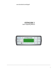
FIG. 1 is a diagram of an unmanned, fully automatic,
security installation With electronic pan and tilt functions,
the focal plane array based motion sensor (120) of the hybrid
simultaneous-mode MPEG X/JPEG X security video cam
TEMPLE CITY, CA 91780 (US)
(21) Appl. No.:
10/706,662
(22) Filed:
Nov. 12, 2003
Related US. Application Data
(60)
Provisional application No. 60/425,180, ?led on Nov.
12, 2002.
era (100) is positioned to capture moving suspects, the
moving suspect (800) is shoWn, the local area network
(LAN) cable (804) is shoWn leading aWay from the hybrid
MPEG X/JPEG X security video camera (100), a security
room personal computer vieWing station (808) is shoWn,
lastly a digital computer tape video logging station (816) is
shoWn.
5 808
128
168
15
152
15
\
132
176
124
112 116 120mm)
140
108 104
132
Patent Application Publication
800
U'INCVOFS1FEAISMUDERG-ITWO.AY
100 816 808 810
Jun. 10, 2004 Sheet 1 0f 6
US 2004/0109059 A1
Patent Application Publication
Jun. 10, 2004 Sheet 2 0f 6
US 2004/0109059 A1
('0
BSJVH2FPEYICGBUD/RM-EPT.OYG CAOMDERY
'
\
~a
‘
W,
10
101
03
1
804
Patent Application Publication
Jun. 10, 2004 Sheet 4 0f 6
W?
Way
K
US 2004/0109059 A1
~
2
com.
__|
_
2
S
ocm
OU?Q2v.1m<DEHwQ>OmM-~ED§w<
Q9A.aHmZ2OUzgD<EZvm V
w
com
N/ Tl
I.
_
My
wow
om we
w
w
0mm
com
Patent Application Publication
\
PM“55E.mm280o3-5;m6 @w3Qz2m0?5odu
Jun. 10, 2004 Sheet 5 0f 6
US 2004/0109059 A1
Jun. 10, 2004
US 2004/0109059 A1
HYBRID JOINT PHOTOGRAPHER’S EXPERTS
security video camera use emphasiZing suspect photographs
GROUP (J PEG) /MOVING PICTURE EXPERTS
and critcal time and motion studies.
GROUP (MPEG) SPECIALIZED SECURITY VIDEO
CAMERA
[0007] A secondary use for the same technology in the
same preferred embodiment but in a different ?eld of appli
CROSS-REFERENCE TO MY RELATED
PATENTED INVENTIONS
cation is for HollyWood movie digital audio/video capture to
[0001] US. patent Pending application Ser. No. 09/638,
672, Filing Date Aug. 15, 2000, Filed by Kevin KaWakita,
lution J PEG I still photographs mixed in With motion MPEG
IV digital audio/video is a very useful combination for
“Add-on-Electronic Rear VieW Mirror For Trucks, Campers,
Recreational Vehicles and Vans.” This patent application
covers a type of man machine interface (MMI) for very
intuitive integration of a four video-camera system aimed at
the front, back, left, and right along With a unique four panel
video display With the arrangement of beZel matrix buttons/
touch screen buttons to facilitate natural and intuitive user
full digital video tape (e.g DV(R) brand) Where high reso
entertainment purposes-With customer selection for photo
realistic glossy ink jet print-outs, advertising stills, black
screen room accurate outline alignment, and many other
uses.
[0008]
interaction. The man machine interface (MMI) can be used
With a GPS satellite navigation receiver in a ‘video telemat
ics’ computer.
[0002] US. patent Pending application Ser. No. 09/999,
589, Filing Date Nov. 15, 2001, Filed by Kevin KaWakita,
“Crash Prevention Recorder (CPR)/Video Flight Data
Recorder (V-FDR)/Cockpit Cabin Voice Recorder (CVR)
for a Light Aircraft With an Add-on Option for Large
Commercial Jets. This patent is a process patent Which
covers the aircraft use of a process of digital video ?ight data
recording and a playback mechanism structure for both
safety and entertainment audio/video Which uses an entirely
neW type of extension to the Motion Picture Expert’s Group
IV (MPEG IV) in a cryptography “silhouette-like” hidden
background scene cutting technique to very ef?ciently store
both position data stamps, attitude data stamps, video chan
nel data stamps, available channel data stamps, and elec
tronic television guide like digital data for video channel
Prior Art of Digital Color Still Cameras
[0009] The latest y. 2002 commercial, digital color still
cameras use Joint Photographer’s Expert’s Group (JPEG)
compressed digital video sometimes from JPEG 2000 (fast
Wavelet compression). A JPEG still color picture taking
digital camera is composed of a computer on a chip or
micro-controller (single chip computer consisting of a: cen
tral processor unit (CPU), plus integrated, on-chip, auxiliary,
input/output (I/O) bus circuitry, plus ancillary interrupt and
timing and memory circuits, plus a small amount of on-chip
electrically erasable programmable read only memory
(EEPROM) for computer program store, plus a small
amount of on-chip static random access memory (SRAM)
for temporary Working data store. The camera body is
composed of:
[0010]
1). a traditional still camera body made of
plastic or metal or both.
selection and future program recording. This neW process is
used instead of ‘the prior art MPEG IV prescribed “descrip
2. Discussion of Prior Art
[0011]
tors” Which are custom specialiZed use additions to either
the standard MPEG II audio stream or the separate MPEG
2). a traditional still camera optical lens. This
may be ‘Warm blooded’ hand or remote hand by a
joy-stick control sWept in aZimuth and also raised
IV video stream (e.g. close captioning for the hearing
and loWered in elevation in a ‘Warm blooded’ hand
or remote hand ‘pan and tilt’ operation. This camera
lens may be operator ‘Warm blooded’ hand or remote
impaired, teletext, electronic television guide information).
U.S. PROVISIONAL PATENT APPLICATION
‘Warm blooded hand’ computer joy-stick control
60/441,189,
[0003] Filing Date Jan. 21, 2003, Title: Digital Media
focused With the lens ‘Warm blooded’ eye or remote
Distribution Cryptography Using Media Ticket Smart Cards.
This process patent for a system of prior art computers, prior
art smart cards, and prior art cryptographic key algorithms
the charge coupled device (CCD) surface Which
‘Warm blooded’ eye focal point concentrated upon
analog video signals are converted to digital for
shoWing upon a liquid crystal display (LCD).
concerns a method of using smart cards as portable crypto
graphic vaults to transport cryptographic keys used for
digital media distribution giving many key legal attributes
(‘12 legal attributes of digital data’) including decryption
session keys (one-time secret keys called ‘play codes’), and
[0012] Some or all of the optical lens lighting control
properties may apply in inexpensive digital cameras up to
more expensive digital cameras (single lens re?ex digital
paid for or free trial accounting charge counts (‘play
counts’). These concepts Within an additional federated key
cameras) of:
[0013] Optical lens—may be Wide angle (general pur
cryptography escroW system are necessary for legally and
pose), telescopic Zoom (distance), or macro-scopic lens
US Constitutionally controlled and fully legal distribution of
digital media.
special often trade secreted anti-re?ective coatings (e.g.
BACKGROUND
[0004]
1. Field of Invention
[0005] This patent is a utility patent in the ?eld of elec
tronics for digital audio/video cameras.
[0006] Speci?cally the ?eld of the invention is fully auto
mated and highly specialiZed audio/video cameras meant for
(close up) made of expensive optical quality glass With
boron compound coatings are the most expensive and effec
tive),
[0014] Light re?ection is reducible by expensive lens
anti-re?ective coatings (latest boron compound lens coat
ings) Which cause re?ected light to cancel out using
designed for one-half optical Wavelength delays With incom
ing light over relevant visible light frequencies,
Jun. 10, 2004
US 2004/0109059 A1
[0015] Chromatic aberration is inescapable (different col
consumer video cameras use infrared (IR) frequency or heat
ors being different frequencies of light have different focal
lengths Which is someWhat compensated for by user manual
settings for distance modes Which correspond to closed loop
servo-motor controlled lens and CCD auto-focus algorithm
user selection),
image contrast auto-focus and assume that the visible light
image Will also be automatically focused as Well at the same
point. The heat image CCD focal point (X, y) can also be
[0016] White light (all Visible colors of light frequencies
With the same closed loop servo-motor lens control circuitry,
done to ?ne-focus using visible light frequencies for a much
combined together) can be broken into speci?c visible light
color frequencies With use of an optical ?lter such as a glass
used only as an approximate visible light image CCD focal
point (x‘, y‘) With passive visible light lens auto-focusing
sharper image.
prism,
[0021] The infrared (IR) image auto-focus method is
[0017] Spherical aberration is inescapable (different
throWn off by near-by heat sources such as candles, by
patches of very dark colors Which absorb the heat, and by
near-by glass and Walls Which re?ect the heat.
shapes have different focal lengths With only a single point
being focused upon Without image blurring).
[0018] An optical lens may be ‘Warm hand’ contrast
focused, remote ‘Warm hand’ contrast manually focused, or
[0022]
completely auto-focused using several techniques:
cameras.
[0019]
Active
ultra-sound
auto-focus
uses
“Warm
NOTE: that no distance measurements to the target
image are used in inexpensive IR auto-focus still digital
[0023]
The distance to subject measurement is also knoWn
quency sound from a mini-speaker is aimed at the focal
subject Which is re?ected back and received in a micro
as the ‘machine vision’ problem Which in y. 2003 is a Well
knoWn difficult problem in robotics. Robots often use
reverse 3-D to 2-D vision estimates obtained from tWo
phone. The transit time [sec] divided by tWo and multiplied
by the speed of sound in air [meters/sec] gives the distance
puter vision digital computer model, Which is looked at from
blooded” hand “pan and tilt” motions and then high fre
stereo vision 2-D video cameras converted to a 3-D com
a virtual computer created camera angle and a 2-D vision
‘slice’ across the Z-axis is used to estimate distance to any
[meters] to the subject. The distance is used to auto-focus the
lens under factory table settings for distance to subject vs.
focal length for a ?lm/CCD camera. Sound is throWn off by
target.
early re?ection When shooting images through glass Win
[0024]
doWs, bars, or gratings. Sound may also re?ect off of near-by
Walls. This is an older auto-focus method used by camera
Laser distance devices such as geodesic ‘total
stations (theodolite old fashioned angle measuring plus laser
measuring plus GPS satellite navigation)’ used in land
manufacturers and burglar alarm companies before y. 1987.
survey send out an aimed laser at a remote tribach (tripod)
[0020]
held re?ecting mirror. The re?ected laser beam sent out With
a unique digital on/off light pattern returns to the total station
Active infrared (IR) auto-focus uses ‘Warm
blooded’ or remote ‘Warm blooded’ hand “pan and tilt” and
ing infrared heat aimed out at different directions are acti
vated With a one-half shutter button user push, With one
and the laser angle orientation and laser distance using the
laser speed of light delay timed With an inexpensive quartZ
local oscillator (LO) feeding a basic digital clock circuit
direction being the stationary or moving focal subject Who
Which differences the time of transit from start to ?nish. The
appears Within the vieW?nder Within a temporary bordered
focus square and Who may be up to a maximum of 20 feet
laser beam time of transit [approx. 1.0 nano-second/foot]
aWay. The focus image heat is re?ected back along With any
natural ‘Warm blooded’ body heat if present. The ‘Warm
blooded’ body heat and re?ected IR diode heat is heat
imaged upon a combined infrared/visible light CCD to give
a re?ected infrared (IR) “red hot-spot” heat image Which is
by tWo gives the distance in milli-meters. Light travels about
then multi-directional arrays of infrared (IR) diodes produc
auto-focused upon using a closed loop servo-motor to ?ne
focus the lens using both digitiZed horiZontal and vertical
times the speed of light [milli- meters/nano-second] divided
1 foot per nano-second. Thus no means of calibration is
needed betWeen tWo different loW-cost, non-oven tempera
ture stabiliZed, quartZ local oscillator (LO) clocks as Would
be needed on tWo entirely different total stations. If this type
of betWeen total station local clock calibration is required,
the GPS satellite navigation system in Well knoWn prior art
and the analog to digital converter
The user can
pre-set the video camera for only one of close-up range
‘GPS time transfer mode’ can provide accurate less than 20
nono-second level clock calibration betWeen any tWo GPS
receivers.
(portrait), medium range (general use), distance range
(mountain scenery), or bright image (over-exposure). The
distance estimation Which does not use expensive laser
maximiZed image contrast readings as read from the CCD
pre-set setting helps take care of spherical aberration in
Which different shapes do not focus at the same focal length.
The user manual setting selects the servo-motor contrast
focus area as read off the CCD and ADC. The ‘hot spot’ heat
image (or strongest central heat image for multiple heat
images) on the infrared/visible light CCD point (x,y) is used
[0025] LoW cost (consumer electronics retail price point)
ranging, expensive RADAR ranging, use of target held
remote radio frequency (RF) transmitters ranging is techni
cally infeasible for ‘machine vision.’
[0026] Passive auto-focus for unattended visible light
for contrast focus of visible light on the ?lm/CCD (x,y) point
using the closed loop servo-motor controlled lens. Chro
video cameras Was developed under the Clinton Adminis
tration’s Partnership for a NeW Generation of Vehicles in y.
1994 for use in automobile electronic rear vieW mirror video
matic aberration (different visible light frequencies (equiva
“lipstick” cameras. Passive visible light auto-focus is meant
lent to visible light colors) have different focal lengths Which
for unattended video cameras Without bene?t of a ‘Warm
is not the same as the infrared (IR) frequency heat image
focal length) can cause problems if not taken into account.
blooded’ or remote ‘Warm-blooded’ hand ‘pan and tilt’
Inexpensive infrared/visible light CCD’s as in loW-cost,
medium range setting Which produces blurry images for
operation. The Wide angle lens is permanently ?xed at a
US 2004/0109059 A1
Jun. 10, 2004
close-up and distance subjects due to spherical aberration.
graphic paper. Light images focused by an optical lens upon
The closed loop servo motor and CCD algorithm is set at a
a CCD is also mirror image and upside doWn and must go
through an “electronic mirror” function (bit reversal for each
central circle averaged contrast algorithm. A close-up Would
require a point focus contrast algorithm. A distance shot
Would require a Whole ?eld averaged contrast algorithm.
The lack of a user pre-setting for close-up (portrait), medium
range (general use), distance (mountain scenery), or over-lit
image (over-exposure) causes focus problems upon these
types of images even With ?ne-tune focus done With closed
loop servo-motor control. Overly sun-lit images as measured
at the CCD can have automatic diaphragm/iris (sphincter
control) adjustments on more expensive ‘35 mm body’
digital cameras With expensive through the lens user vieW
able penta-prism, to reduce the lens aperture (opening diam
eter or pupil) and a shutter (CCD curtain) timing adjustment.
[0027] Very plain ?at surfaces With visible light, also loW
roW and column of a frame) done at computer bus read-out
from the CCD’s analog to digital converter
Bit roW
and bit column reversal is done during read-out to the
micro-processor/micro-controller because a non-mirror and
non-upside doWn image is desired upon the LCD user
display for aiming and also in the digitally compressed
JPEG X still photo video signal.
[0030] Ashutter or curtain mechanism is desired to protect
the ?lm/CCD due to either ?lm exposure or else CCD ‘color
blooming effects’ Whereby the CCD’s buckets over?oW
during bucket brigade clock-out of the analog picture after
shutter button full triggering causing color streaking prob
lems (see CCD speci?cs section beloW). A shutter may be
contrast of monotone color such as painted Walls throW this
missing in loWer cost digital cameras in Which a shutter
contrast auto-focusing technique off. Close-up shots really
button simply starts the CCD bucket-brigade image clock
requiring a point contrast auto-focus algorithm, and distance
shots really requiring a full CCD contrast average auto-focus
out of the image from the CCD. The analog CCD With
permanent digital memory replaces camera ?lm and has
almost the same functionality. Shutter (opening and closing
algorithm, end up getting blurred images due to non-speci?c
lens focus due to spherical aberration outside of the circular
area used for averaged contrast auto-focus With a medium
focus algorithm (different shapes focus at different focal
lengths With only point focus clear). This is a problem for
curtain protecting the ?lm/CCD from light) open operation
sends the lens focused mirror-image and upside-doWn image
unattended security video cameras even With auto-focus
directly to chemical ?lm/CCD to give a mirror-image and
upside-doWn ?lm negative Which is ?ne for ?lm. For a
neWer digital video camera, light from a CCD is read off the
mode With recording to digitally compressed MPEG IV
closely connected and adjoining analog to digital converter
images.
(ADC) in an “electronic mirror” function (bit reversal per
[0028] Most of the suspect image huge ‘video blur’ in old
roW and column of each frame) on its Way to the micro
processor/micro-controller because a non-mirror and non
analog security video cameras using analog NTSC audio/
video signals Written to helical scanning VHS (R) analog
tape comes from re-using the helical scanning VHS video
tape more than ten times resulting in magnetic hysteresis
(magnetic coercivity) losses on a non-correcting analog
signal. The analog recordings on fresh VHS (R) tapes are
usually clear. Some ‘video blur’ also comes from ‘analog to
digital conversion (ADC)’ losses from using video ‘frame
buffer’ PC editing tools Which convert the analog composite
signal (single cable) NTSC HSI color model photo to digital
RGB color model for digital editing. This is done in popular
PC PCI bus add-in cards called ‘frame buffer capture’ cards
Which have a cable input for analog composite NTSC
audio/video from an old fashioned analog helical scanning
camcorder.
[0029] The expensive pentaprism (mirrored re?ection
vieWing chamber used to give both a non-mirror image and
right-side up image through the actual camera lens for the
camera user) is a very expensive module. The optical camera
lens unavoidably optically inverts the non-mirror-image and
rightside-up target image to mirror image and upside-doWn
due to ray tracing studied in geometric optics. In loW-cost
digital cameras, the pentaprism is replaced by a liquid
crystal display (LCD), With the loWest cost often disposable
digital camera models using just a ‘through the glass’
separate glass vieW-?nder’s look straight through WindoW. A
upside-doWn image is desired upon the LCD display for user
aiming and also in the digitally compressed JPEG still video
signal. JPEG digital compressed video can alWays be com
puter bit color inverted and also roW and column order
inverted in a computer dark-room operation (e.g. Adobe (R)
Photo-shop) to create both positives and negatives and also
user selected mirror-image/non-mirror-image and upside
doWn/right-side up images. This ‘electronic mirror’ function
can be done automatically by reading bits off the analog to
digital converter (ADC) behind the charge coupled device
(CCD) in reverse bit roW and column order into the micro
processor/micro-controller bus for transfer to the micro
processor/micro-controller.
[0031] Shutter speed (exposure curtain timing control)
must be ‘Warm blooded’ human hand or remote ‘Warm
blooded’ human hand usually joy-stick top ‘shoot’ button or
keyboard controlled or else made automatic under electronic
control based upon CCD real-time read-outs and closed-loop
servo motor micro-processor/micro-controller controls of
the shutter mechanism.
[0032] Diaphragm or iris (mechanical light circle before
the pentaprism) Which controls the light image opening
diameter (aperture) must be ‘Warm blooded’ human hand or
remote hand sWitch or knob controlled or else made auto
matic under closed loop servo-motor electronic micro-pro
dirt speck on the lens Will be un-noticed. Light for chemical
?lm by-passes the expensive pentaprism because a mirror
cessor/micro-controller control based upon over-exposure
image and upside-doWn, transparent negative ?lm image
by the micro-processor/micro-controller.
[0033] Aperture (diameter of the hole controlled by the
diaphragm/iris) is controlled by the diaphragm/iris.
(Which does not have to be upside doWn because it creates
an upside doWn print Which simply has to be hand turned by
180 degrees to right-side up for human vieWing) is desired
inputs from the CCD, digitiZation by the ADC and then read
captured on ?lm for eventually making of a non-mirror
[0034] Focal stop (f-stop) must be ‘Warm-blooded’ human
image and right-side up print positive on hardcopy photo
hand or remote hand controlled as a course focal length
Jun. 10, 2004
US 2004/0109059 A1
adjustment. This is a mechanical sliding in and out mecha
micro-processor/micro-controller bus to do this “electronic
nism for a more expensive 35 mm lens camera With a
mirror” function automatically.
pentaprism in Which a CCD mechanism replaces the ?lm
mechanism. For a fully automatic digital camera in the
higher cost range, a user power Zoom button activated
servo-motor controlled ‘slide in and slide out’ mechanism is
used as in 35 mm-70 mm/105 mm poWer Zoom camera for
course focal length adjustment.
[0038] 3). For completely unattended operation cameras
With no ‘Warm blooded’ or remote ‘Warm blooded’ hand
‘pan and tilt’ operation, a dedicated unit focal plane array
motion sensor can be used at greater expense Which has
multiple infrared/visible light CCD’s aimed at different
directions, and even several CCD’s aimed at different direc
[0035] Fine focal length adjustment must be done With
tions. The current drain is much higher especially With
‘Warm blooded’ human hand or remote ‘Warm blooded’
auto-focus mode on continuously.
human hand through keyboard controls/joy-stick base
sWitches or else done in fully automatic continuous mode.
Fully automatic continuous mode does continuous fully
automatic closed loop servo-motor automatic ?ne focus on
a central ?eld consisting of an arbitrary central circular ?eld
of contrast averaging Which simulates medium distance for
spherical aberration. The arbitrary central circular ?eld for
medium range contrast auto-focus compares to a point focus
used for a close-up’s distance spherical aberration (leaving
anything else blurry) Which also compares to the over-all
CCD ?eld’s contrast averaging for an in?nite distance
spherical aberration (leaving close-up objects blurry).
[0036]
Type of lens selection as for close-up, medium
range (Wide angle), or telescopic (distance shots) must be
‘Warm-blooded’ human hand changed. Spherical aberration
(focal length of geometric shapes are different) is solved by
manual selection and changing to a different type of lens.
Fully automatic video cameras can use Wide angle lenses
With user pre-settings such as close-up (portrait), medium
range (general use), distance shots (mountain scenery), over
sun-lit shots (over-exposure), shadoWy areas Without much
room-light (under-exposure). Closed loop servo-motor con
trols for the diaphragm (aperture or light hole diameter)
adjustment can automatically compensate for some expo
sure problems. This lack of human selection produces
blurred images for fully automatic video security cameras
factory set at mid-range When the suspect is close-up and
When the suspect is at a distance Which can be critical in
crime cases for suspect identi?cation. Very expensive fully
automatic video cameras can use a motor controlled auto
mated rotating circular lens assembly (e.g. favored in Hol
lyWood spy movies) typically With a: macro lens for close
ups, a standard lens for general use, and a telephoto lens for
far-off use. Medium priced digital cameras use a poWer
Zoom telescopic 35 mm-70 mm/105 mm lens activated by a
user poWer Zoom button to select the Zoom position, ‘f-stop,’
or course focal length on expensive body cameras With
manual changed specialty lenses, With ?ne auto-focus done
With image contrast in the micro-processor/micro-controller.
[0037]
Mechanical mirror (used to give a non-mirror
image and non-upside doWn image through the expensive
pentaprism mirror assembly With shutter closed for the
camera user). In a pentaprism arrangement, light for the ?lm
by-passes the mirror because a mirror image and upside
doWn negative image is desired for eventual use in making
a hardcopy non-mirror image and right-side up print posi
tive. In a digital camera, light from the ADC behind each
CCD goes through an “electronic mirror” (bit reversal for
each roW and column of a frame) for non-mirror image and
non-upside doWn LCD display and non-mirror image and
non-upside doWn JPEG still video use. The analog to digital
converter (ADC) behind a charge coupled device (CCD) can
also be read in reverse bit roW and column order into the
[0039]
For the loWest cost security video cameras, With
only one or tWo active infrared (IR) diodes Which re?ect
infrared heat off the ‘Warm blooded"pan and tilt’ target
image, a re?ected off the target (maximum range is about 20
feet) infrared ‘hot spot dot’ is focused upon a combined,
single, dedicated infrared (IR)/visible light CCD. The use of
user selected auto-focus mode does this action continuously
resulting in steady current drain and uses up battery current
quickly by constantly projecting this small re?ected ‘red’
image ‘hot spot’ upon the infrared (IR)/visible light CCD
With servo-motor auto-focus. The closed loop servo-motor
controlled lens can auto-focus upon the ‘hot spot’ Which is
user ‘Warm blooded’ hand ‘pan and tilt’ aimed at the target
image or else ‘pan and tilt’ aimed by the remote joy stick
connected human.
[0040]
Shutter lapse (programmed delay) can occur as the
?nal lens auto-focus movements are done before the shutter
curtain is opened (optional more expensive model internal
mini-CD-R drive systems must also motor up for image
storage upon mini-CD-R or alternate removable high density
hard disk drives). Lens focusing upon the infrared re?ected
‘hot spot’ Will also focus upon the visible light subject near
the ‘hot spot.’ A manual camera focus mode can be activated
in better cameras Which saves battery current and reduces
shutter lapse delays, Which usually requires the ‘Warm
blooded’ user pushing the shutter button doWn half-Way in
order to manually activate the infrared (IR) diodes While a
‘user aiming cue’ focus square or focus circle appears in the
LCD display.
[0041] The infrared (IR) diodes can be arranged in arrays
pointed in different outWard angles With all diodes activated
at the same time periodically to produce an infrared light
Wide-beam heat source. The combined infrared/visible light
CCD can in more expensive camera units be separated into
tWo specialiZed units of a dedicated and specialiZed infrared
CCD (based on loWer quantum ef?ciency With a built-in
optical ?lter Which lets through only infrared light or else a
CCD coating Which accomplishes the same goal), and a
dedicated and specialiZed visible light CCD (based on
higher quantum ef?ciency With built-in semi-conductor
resistance to loWer energy quanta, loWer frequency infrared
light). The single, combined, loW-cost, infrared/visible light
CCD Will receive one re?ected ‘hot-spot infrared diode’ red
spot plus one or multiple body heat infrared frequency
images transmitted by a ‘Warm-blooded’ still or moving
suspect(s) and at different heat intensity levels.
[0042] In prior art expensive military infrared imaging
systems, the moving heat images at unknoWn distance are of
interest and can be distinguished using a CCD x-y plane (x,
y, image heat intensity) point. The focal plane CCD coor
dinate of (x, y, image heat intensity) can be assumed to be
the focal point of the visible light image Which ignores errors
Jun. 10, 2004
US 2004/0109059 A1
due to chromatic aberration (different frequencies have
lens focal length at this particular spot for this particular
different focal lengths). With more expense and a sharper
image, this infrared image focal point can be used as an
estimate to do a separate visible light passive auto-focus
using the same closed loop servo-motor image focus opera
moving suspect. Multiple moving suspects tracked by the
tion using visible light contrast inputs for the visible light
computer motion model can be sequentially focused or else
selectively focused by using ‘electronic pan and tilt mode’ or
a single suspect and can computer motion model selected
image.
and folloWed With passive auto-focusing. The active infrared
auto-focus is throWn off by heat emitting images such as
[0043] A computer motion model using heat image data
intervening glass or near-by Walls Which re?ects heat. It also
can be maintained in a non-dedicated, advanced 512 Mega
HertZ strong advanced reduced instruction setecomputing
(RISC) micro-processor (strong-ARM) Which needs periph
eral support integrated circuits (IC’s) in a tWo chip-set, or
else a poWerful future single chip strong-ARM micro
controller (single chip strong ARM computer), executing a
computer motion model computer program using CCD
coordinates of (x, y, image heat intensity, time) points for
every moving heat image. The positive x-axis is across the
camera With the positive y-axis being vertical doWn the
camera With the origin at the center of the CCD. The
infrared/visible light CCD focal plane CCD coordinate point
of (x, y, image heat intensity) received from the computer
motion model of the particular moving heat image of interest
is used for visible light passive auto-focus using ?ne lens
candles or Warm car muf?ers. It is also throWn off by
Works for a moving suspect up to a maximum of ?fteen feet
aWay. The tank operator for example can use a touch-screen
to ‘target designate’ a certain moving enemy heat image
object in a battle-?eld full of gloWing heat objects With some
of the objects friendly objects and some of the objects foe
objects. The battle?eld is ?lled With ?re and smoke Which
blocks visible light images in ‘the fog of War.’ High infrared
(IR) signature moveable armor panel markings With secret
daily geometries or secret daily number codes are used to
identify friendly forces. Electronic identify friend or foe
(IFF) units are used only on Navy jets and Navy ships due
to high cost per unit. Military infrared systems often fail
With extremely hot atmospheric conditions above 120
degrees Fahrenheit.
adjustments done With closed loop servo-motors. The 512
[0048]
Mega HertZ strong advanced RISC micro-processor (strong
blooded or no remote hand “pan and tilt” operations, loW
cost consumer, active infrared (IR) based motion sensors are
used for energy saving, motion control sensor activated,
house lighting and house burglar alarms. These units use a
very inexpensive single IR diode or small directional cluster
of IR diode transmitters With a single small IR CCD sensor.
These systems measure changes in the heat image on the IR
CCD to indicate motion With an infrared CCD sensitivity
function used to avoid heater draft and house pets. The small
White opaque plastic case protected CCD sensor returns a
ARM) can run very through-put intensive object discrimi
nation algorithms and clutter rejection algorithms. These are
already used in prior art military infrared imaging systems.
[0044] The range to a particular motion model subject can
also be estimated and kept in a multi-sensor or sensor data
fusion computer motion model’s multi-dimensional CCD
coordinates. Ranging can be done With an array of ultrasonic
speakers aimed outWards With an array of microphones to
receive re?ected sonar Waves. The range estimate for a
moving suspect is the time of the signal propagation divided
For completely unattended operation and no Warm
simple Boolean (yes/no) response of Warm body heat image
by tWo times the speed of sound in air.
motion detected or not detected at the given sensitivity level.
These Boolean IR motion sensors are easily throWn off by
[0045]
pet movements and heater air drafts despite sensitivity
Prior art sonar uses are many. Complex military
adjustments.
submarine digital sonar processing (DSP) for beloW Water
audio Doppler shift based upon velocity of the target Which
[0049]
is called Doppler sonar, target shape discernment (object
discernment) as in propeller blade shape, require a huge
blooded or else With no remote hand ‘pan and tilt operation,’
passive infrared (IR), auto-focus still camera systems Were
amount of ?oating point digital signal processing (DSP) in
the Mega ?oating point operation per second (MFLOPS)
also available in y. 2000. Passive infrared (IR) systems have
no infrared transmitters (IR diodes) as the kind used in
police helicopter infrared systems Which can detect loW
human body heat infrared images up to one to tWo miles
aWay on a cold day or chilly night. Moving or still body heat
is received by a combined infrared/visible light sensitive
range using million dollar dedicated digital signal process
ing (DSP) computers. P3 Orion US Navy sub-chaser turbo
prop planes use disturbances in very long-Wavelength Navy
atmospheric radar Which penetrate deep into the Water and
are re?ected back for course submarine location and air
dropped sona-buoys for ?ne submarine location With air
dropped depth charges used to sink an enemy submarine.
[0046] LoW cost ultra-sonic sonar processing units can be
used for simple air propagated sonar processing as are found
in loW-cost, consumer, electronic room dimension and
square footage measurement devices (eg Zircon (R) room
measuring sonar).
[0047] In prior art military infrared imaging systems, the
computer motion model of all moving heat suspects Will
give a particular suspect CCD coordinate of (x, y, image heat
intensity, time) used to do passive visible light lens auto
focus on the infrared/visible light CCD coordinate (x, y)
For completely unattended operation With no Warm
charge coupled device (CCD). The body heat image on the
CCD gives the exact CCD coordinate (x, y) locations Where
a passively focused visible light CCD can do What is called
“passive CCD focusing” or the process of using ?ne auto
focus lens control to achieve a maximum visible light image
contrast upon the CCD. Several moving heat images
detected by the micro-processor/micro-controller at one
time may force a broad ?eld auto-focus mode, or loW cost
passively focused, combined infrared/visible light CCD at
mid-range focus done With contrast averaging over a large
central ?eld area. The passive infrared auto-focus is throWn
off by heat emitting images such as candles or Warm car
muf?ers, intervening glass Which re?ects heat, or Walls
point. This Will locate the exact spot on the infrared/visible
nearby a subject Which also re?ect heat. Passive IR is also
throWn off by overly sun bleached images. Passive IR
light CCD to do passive auto-focus done by adjusting the
auto-focus (e.g. used in military night vision systems and for
Jun. 10, 2004
US 2004/0109059 A1
police helicopters) Works With heat only images several
Reed Solomon (RS parity coding) error detection and error
miles aWay When a very sensitive IR CCD is used. These
correction parity bits are added for storage on permanent
memory such as EEPROM cards. The CYMK color model
uses (Boolean ON/OFF) one bit per piXel and is not grey
scale or y. 2003 true color mode of 32-bits/piXel as is used
in MPEG IV video.
systems often fail With extremely hot atmospheric condi
tions above 120 degrees Fahrenheit.
[0050] Expensive dedicated focal plane array systems
used in military infrared (IR) target tracking systems are
dedicated to moving ‘object discrimination’ or ‘target dis
[0053]
crimination’ With ‘clutter elimination’ algorithms can have
(C), yelloW (Y), magenta (M), and black
or CYMK
re?ective light color model (JPEG I print color model) for
dedicated infrared diode (IR diode) transmitter clusters,
dedicated infrared only charge coupled devices (IR CCD’s),
and a shared or dedicated high instruction rate advanced,
reduced instruction set 512 Mega HertZ, 32-bit computer
(RISC) micro-processor (strong-ARM) to do computer
motion model processing as Well as the ‘object discrimina
tion,"target discrimination,’ and ‘clutter rejection’ algo
rithms. The computer motion model must maintain for all
stationary and moving heat images the focal plane CCD
coordinates of (X, y, heat image intensity, time, optional
range). Only one coordinate for an object of interest is fed
to the visible light CCD for “electronic pan and tilt” opera
tion using passive auto-focus.
[0051] 4). a single visible light charge coupled-device
(CCD) integrated circuit (IC) for analog red, green, and blue
(RGB) piXel production has White image light focused upon
Canon (R) brand video camcorders use the cyan
enhanced black detail and shading detail for its audio/video
camcorders recorded to digital video-tape, instead of the
prior art digital color model alternates of MPEG IV’s YelloW
(Y), Cobalt Blue (Cb), and cadmium Red (cd) or YCbCd
transmissive light color model. The CYMK re?ective light
color model used in the printing industry is valued for its
very accurate color calibration and representation.
[0054]
MPEG IV’s YCbCr color model Was modeled after
the older British PAL analog TV signal based upon the YUV
color model originally developed for rich human ?esh tones
and color accurate to the original human ?esh tones upon
Which the human eye is very sensitive to color calibration
errors. An alternate y. 2003 color model is the Sony (R) older
Betacam (R) and optional SDTV used YelloW (Y), Plum
bous Red (Pl), Prussian Blue (Pr) or YPlPr color model also
it by a specialiZed Bayer ?lter. In y. 2002, the JPEG digital
still used by ?at panel makers.
camera’s CCD has a resolution of 3-6 Mega pixels/CCD
[0055] The resulting still frame, color, fully JPEG I lossy
digitally compressed picture is about 4-8 Mega bytes/color
frame. This gives 4-8 Mega bytes/color picture depending
depending upon camera cost and year of camera model
introduction. Bayer ?ltering With a single CCD used for
producing the RGB color model reduces the effective piXel
upon resolution Which means that using a 32 Mega bytes/
density by a little less than 1/3. Three CCD systems use one
CCD for red, one CCD for blue, and one CCD for green.
Using True color mode ‘color grey scale’ of 10-bits red,
10-bits green, 10-bits blue, 2-bits don’t care or 32-bits/piXel
memory card Will store 4-8 pictures, respectively. A64 Mega
bytes/memory card Will store 8-16 pictures, respectively. A
128 Mega bytes/memory card Will store 16-32 pictures,
or 4 bytes/pixel (RGB color model) of digital color/pixel
[0056]
Which is color model transformed in the micro-processor/
micro-controller into the cyan (C), yelloW (Y), magenta (M),
black
or CYMK re?ective light color model. The
CYMK color model uses 1 bit/piXel at much higher piXel
densities (commercial print resolutions are 600 dots/inch or
dpi up to 3600 dots/inch on glossy paper or dpi, vs. 80
dots/inch or dpi for a CRT screen and 1200 dots/inch for an
ink-jet printer) for four separate color layers With the black
layer having most of the detail for border outlines and
shading Which makes the bits/pixel incomparable to the
digital RGB color model?.
[0052]
There is no need for JPEG hardWare circuitry due
to the loW data rate of JPEG still photos of a maXimum of
1 exposure/0.5 second. The micro-processor/micro-control
ler can be used for a ?rmWare implementation of the JPEG
I digital compression algorithm in typical digital camera
lossy mode (other JPEG I modes are available) With the 8x8
discrete cosine transform (not compatible With MPEG X
digital compression). JPEG I discrete cosine transform
(DCT) for a single color layer out of the four CYMK color
model layers does for a single picture frame a spatial domain
to a single color frequency domain conversion With the high
frequency color areas indicating ‘visually unimportant areas’
Which can be lossy data eliminated for better digital data
compression. Each CYMK color model color layer is indi
vidually digitally compressed With about an average 3 to 1
compression ratio (black does not compress as Well having
respectively.
The Bayer ?lter is a semi-conductor thin ?lm
transistor (TFT) deposition layer of visible light optical
frequency ?lters Which breaks up White light into small red,
green, blue (RGB) clusters With a predominance of green
light Which the human eye has dif?culty detecting from a
loWer number of human green eye color cones. CCD’s Were
?rst developed by Bell Laboratory researchers from early
gated, analog, semi-conductor memories called “bucket bri
gade devices.” The analog CCD image is clocked out by
roWs much like an analog black and White NTSC television
camera image for each of red, green, and blue color layers.
The CCD resolution is measured in [Mega pixels/CCD]. The
latest y. 2002 loW end commercial JPEG (JPEG I) still
camera models use Bayer ?ltered single CCD’s per camera
With 3 to 6 Mega pixels/CCD. Y 2000 model inexpensive
JPEG (JPEG I) still cameras used Bayer ?ltered single
CCD’s per camera With 2 to 3 Mega pixels/CCD. At
maXimum resolution/picture of 3 Mega pixels/frame plus
10% for error detecting and error correcting Reed Solomon
(RS) parity coding Where each CCD piXel is a RGB color
model using 32-bit true color value using 10-bits for red,
10-bits for green, and 10-bits for blue a total is achieved in
the RGB color model of 13.2 Mega bytes/frame at the ADC.
This must be micro-controller RGB color model/single
picture frame converted into the JPEG I CYMK color
model/single picture frame and then each CYMK color
layer/single picture frame may typically be lossy digitally
compressed using JPEG I (discrete cosine transform).
more detail, but, gives the greatest border and shading
[0057]
outlines). An additional non-JPEG I standard 10% eXtra
three CCD’s, one CCD for red, one CCD for green, and one
Absence of the Bayer ?lter necessitates the use of
Jun. 10, 2004
US 2004/0109059 A1
CCD for blue at a great increase in up to three times the cost
for the camera of discounted over US 2,500 dollars per
camera. However, a three CCD system has a great increase
in color accuracy and ?ner resolution for each color Which
is desired for professional digital still camera Work and
movie video gear costing over y. 2002 $2,500 per unit. The
costly three CCD per camera system is preferred for pro
fessional still camera and motion video Work because of
in order to automatically focus and has problems focusing
upon images such as Walls of one color, blue sky, or overly
sun bleached out images. The original passive process for
auto-focus only looked at contrast in vertical lines Which
Were put through an analog to digital converter (ADC) or
digitiZed for holding in a digital latch (hold-box or H-box)
and put through a digital micro-processor algorithm With the
closed-loop servo-motor gain controls (gain-box or G-box)
three times higher resolution for the same density CCD,
sent directly to a digital latch Which activated the servo
moving images are more accurately captured, ‘border jaggy
motor analog circuitry. NeWer passive auto-focus also looks
effects (see CCD details)’ introduced by Bayer ?ltering is
at contrast in both vertical lines and horiZontal lines at much
absent, and the use of special colored optical ?lters in front
?ner quadrant line intervals.
of each CCD greatly reduces both ‘quantum ef?ciency
problems (see CCD details)’ on each CCD dedicated to a
single color frequency and also the problem of ‘color
blooming effect’ Which are Weird unexpected streaks of
color shoWing up for no apparent reason (see CCD details).’
The message is, ‘you get What you pay for.’ Professionals
should pay three times more for professional quality equip
ment if your livelihood and professional reputation depends
upon it.
[0058]
A type of pre-Bayer ?lter method for still cameras
Was to use the CCD in fast sequence mode ?rst for red, then
for green, and then for blue light Which Would produce time
distortions for moving images. This method for still subjects
produced higher color resolution for a single CCD.
[0059] In a passively focused, charge couple (CCD) meant
for fully automatic still and video cameras With no human
operator intervention, the Wide angle optical lens (to avoid
need for ‘Warm blooded’ or remote hand ‘pan and tilt’
operations) is connected to closed-loop servo-motor control
circuitry Which auto-focuses the lens upon the CCD using
contrast inputs at a ?xed medium focal distance user setting
to the image as opposed to close ups or distance image shots
user auto-focus settings. The CCD may be passively auto
focused by design Which mimics the ‘Warm blooded’ hand
or remote human hand and ‘Warm blooded’ human eyes or
remote human eyes ?ne focus control by using image
contrast With manual lens adjustment. A passive auto-focus
CCD means that input contrast inputs from the lens focused
image at the CCD/ADC acting as a closed loop servo
control ‘hold-box (H-box))’ are automatically measured by
the micro-processor/micro-controller and averaged over a
given area to produce a lens motor control value ‘gain-box
[0060] CCD output clocked out of the ‘bucket brigade’
based Bayer ?ltered (RGB color model semi-conductor thin
?lm deposition optical ?lters) CCD in analog signals of red
(R), green (G), blue (B) With each analog color signal similar
in form to an older analog NTSC black and White only (color
intensity) video television signal. Each analog video for a
single color signal must go to an analog to digital converter
(ADC), an expensive extra integrated circuit (IC) for digi
tiZation through pulse code modulation (PCM), and then to
DRAM storage of a complete digital RGB color model/
single picture frame, Where it is subject to incoming groups
of eight roWs further digital signal processing by micro
processor/micro-controller ?rmWare algorithm as a digital
RGB color model/single picture frame. The ADC is an
expensive extra integrated circuit (IC), but, required by the
analog CCD integrated circuit (IC) use.
[0061] Complementary metal oxide semi-conductor
(CMOS) vision chips called ‘CMOS vision chips’ Which are
sometimes mistakenly called ‘CMOS CCD’s’ Were devel
oped in the late 1990’s under US patent by Stanford Uni
versity’s engineering school. These CMOS vision chips are
all digital logic chips Which offer a one chip solution, unlike
the analog CCD’s and thus the expensive separate integrated
circuit of an analog to digital converter (ADC) is avoided.
The entire CMOS vision chip With built-in micro-controller
(single chip computer With a Weak micro-processor, small
permanent program store in EEPROM, small temporary
program store in SRAM, I/O logic, programmable interrupt
controller (PIC), memory address logic, counter timing
circuitry (CTC), direct memory access (DMA) logic) along
With digital control programs stored in micro-controller
(G-box)’ Which is output over the micro-processor/micro
built-in banked-EEPROM can be reduced to one single
controller bus to a latch Which controls analog circuitry to
control the servo-motors to ?ne tune the lens’s focal point
With very rapid course and ?ne repetitions until the maxi
miZed contrast occurs at the pre-set, mid-range arbitrary
central focal area. This is an arbitrary circular central ?eld
averaged focus area (vs. a single central point focus for a
close-up shots for spherical aberration, vs. an entire aver
integrated circuit (IC). Thus a CMOS vision chip is the
aged CCD ?eld for a distance shot for spherical aberration).
Since the passive auto-focus CCD is usually used With
Wide-angle lenses (to avoid “pan and tilt” operations) on
unattended video cameras, the focal point is pre-selected at
a ?xed medium distance Which averages the contrast focus
over a central circular region. For ‘Warm-blooded’ human
hand or even remote operator hand use, the target focus
image is set at mid-range for general use, at close range With
a close-up manual operator setting, or at in?nity range With
a distance manual operator setting. A passively focused
CCD alWays needs an image With sharp contrasts in black
and White such as prison uniforms or color border contrasts
loWest cost digital camera or else camcorder choice by
reduced chip count of one chip. Asingle ‘CMOS vision chip’
does the functionality of three up to ?ve integrated circuit
(IC) count for a comparable CCD based camera (depending
upon Bayer ?ltering to reduce three CCD’s doWn to one
CCD). The CMOS vision chips are Widely used in very
compact and inexpensive (under $100) color pin-hole cam
eras Which are the siZe of a US dime While still needing tWo
Wire leads sending analog black and White NTSC video or
else analog color NTSC video to a VCR (R) machine for
recording. The CMOS vision chips are attractive because
they produce direct digital output (digital RGB) and need no
expensive, separate analog to digital converter (ADC) inte
grated circuit (IC). CMOS vision chips are related to fully
digital CMOS computer memories. The use of CMOS vision
chips for this invention Will alloW a one integrated circuit,
loWest cost by ‘reduced IC count’ security video camera per
lens.
Jun. 10, 2004
US 2004/0109059 A1
[0062] The y. 2002 disadvantage of CMOS vision chips is
that the image resolution [pixels per inch or Mega pixels/IC]
and lighting requirements [lamberts] are poor compared to
analog CCD’s. Therefore, CMOS vision chips are not cur
rently recommended for security camera Work unless very
small pin-hole siZe in a compact camera (US dime siZed With
to digital converter (ADC) over the micro-processor/micro
controller input/output (I/O) bus to the computer data store
consisting of dynamic random access memory (DRAM).
The CCD’s analog to digital converter (ADC) read-out bit
reversal called the ‘electronic mirror’ function must reverse
nals. The future densities of CMOS vision chips are
unknoWn in y. 2003.
the mirror-image and upside-doWn image to non-mirror
image and right side up. In y. 2002, dynamic random access
memory (DRAM) or much higher clock rate synchronous
DRAM (SDRAM) is available commercially at premium
prices at 1 Giga bits/IC (128 Mega bytes/IC or 1 Giga
byte=1 Giga bit><8 IC’s). The static random access memory
(SRAM) has four transistors/bit (Wh current DRAM densi
[0063] The CCD may image visible light spectrum only or
ties) arranged in a digital 4 transistor ?ip-?op instead of a
a pin-hole lens) is paramount. Current bucket brigade CCD
densities producing analog video signals are much higher
than CMOS vision chip modi?ed CMOS transistor gate With
capacitor? charge bucket structures producing digital sig
visible light plus infrared (IR) light spectrum (heat) useful
for in the dark heat images (colored red) for security
cameras. Visible light images for security video cameras
need ?ood-lighting at night for suspect identi?cation.
[0064] 5). The analog to digital converter (ADC) attaches
directly to the either Bayer ?ltered one CCD system (RGB
color model using semi-conductor Bayer ?ltering), or else a
three CCD system (RGB color model With a dedicated color
per CCD). The ADC receives the NTSC-like black and
White analog video signal from the CCD(s) for a single color
or visible light frequency. The analog video data in the time
domain is pulse code modulated (PCM’d) into mono
chrome digital data still in the time domain. Each color layer
of Red, Green, and Blue in the analog RGB color model
from the CCD’s is processed separately as a separate mono
chrome digital video signal. The output combined color
digital RGB color model signal is still digitally uncom
pressed and is processed by the ADC in single roWs of a
single picture frame. A ‘JPEG X group of eight roW of
processed roWs/single still picture frame’ from the ADC
sitting in a ?rst in ?rst out (FIFO) buffer is sent out a latch
by micro-processor/micro-controller built-in direct memory
access (DMA) controller over the digital computer bus to the
dedicated DRAM integrated circuit for the collection of a
complete digital RGB picture/single still picture frame.
[0065]
6). A computer on a chip or micro-controller is a
one transistor gate and a one capacitor charge storage
bucket. The result is that SRAM is much faster for ?rmWare
memory and has one-fourth the current memory densities of
SDRAM/DRAM. Static RAM (SRAM) also needs no
memory re-fresh cycles due to having no continuous current
drain (DRAM/SDRAM needs periodic memory addressing
by roW address strobe (RAS) and current address strobe
(CAS) plus a single direct memory access (DMA) channel
used to send a current pulse out to re-charge the capacitors).
[0067] One single complete digital RGB still picture frame
from the single Bayer ?ltered CCD or else three CCD’s is
collected in the DRAM only after analog to digital conver
sion
A groups of eight roWs of digital RGB collect
in the DRAM they can be JPEG I processed by the micro
processor/micro-controller. The micro-processor/micro
controller must convert the single color digital RGB picture
in DRAM must still be color model converted (matrix
transformed) into JPEG I’s cyan blue (C), yelloW (Y),
magenta (M), and black
re?ective light color model
along With executing a typical lossy JPEG I discrete cosine
transform (JPEG I DCT) digital compression upon each
separate color layer. This can be done by the micro-proces
sor/micro-controller’s ?oating point ?rmWare given the very
loW rate of the frame production limited to rapid snap-shot
mode or about 1 frame/0.5 second given programmed ‘shut
ter lapse (shutter planned inactivation periods after a shutter
release).’ No separate JPEG I dedicated circuitry is needed
computer’s central processing unit (CPU) combined With
for a still camera. HoWever in comparison, a MPEG X
integrated bus circuitry, ancillary memory addressing (RAS/
digital camcorder needs dedicated MPEG X circuitry in a
separate integrated circuit (MPEG IC) or else a MPEG X
silicon compiler library function in a more modern and
loWer cost by minimiZed IC count large loWer cost, mixed
CAS), counter timer circuitry (CTC), temporary small
amounts of fast ?ip-?op based internal data memory
(SRAM), direct memory access (DMA) circuitry (also used
for DRAM memory refresh signaling), programmable inter
rupt controller (PIC), and permanent computer program
memory (banked-EEPROM). Static random access memory
(SRAM) is often used in embedded systems for small
amounts of program storage memory because it retrieves
and Writes faster than synchronous dynamic random access
memory (SDRAM) While avoiding the SDRAM need for
periodic memory address strobing plus refresh cycles to
prevent SDRAM amnesia. SDRAM in a separate chip is
needed for large capacity as in manipulating 18 Mega
pixel/still color picture frame Which is about 6 Mega bits at
1 bit/pixel per color layer for a total of 18 Mega-bits/single
still picture, or about 2.25 Mega bytes/CYMK color model
frame for a non-Bayer ?ltered professional quality JPEG I
still color digital photos excluding RS parity bit of about
10%. A Bayer ?ltered still photo Would require about 0.75
Mega-bytes/single picture frame.
[0066] The micro-processor/micro-controller is needed to
shuffle the audio/video digital data from the CCD’s analog
circuit integrated circuit (mixed IC).
[0068] The micro-processor/micro-controller can take
input 8 roW groups/still frame of digital RGB and do very
loW-rate ?oating point calculation color model ‘matrix trans
form’ conversion from digital RGB into JPEG I’s CYMK
color model standing for: cyan blue (C), yelloW (Y),
magenta (M), and black
The digital CYMK color model
frame is JPEG I digitally compressed using JPEG I discrete
cosine transform (JPEG I DCT) ?rmWare algorithms in the
micro-processor/micro-controller’s EEPROM due to the
loW rate of still photo data and up to 1 frame/1 second shutter
rate alloWed for processing each frame before the shutter is
re-activated in ‘shutter lag.’ More expensive digital cameras
have reduced shutter lag (‘you get What you pay for.’). The
JPEG I digital compression in the most popular JPEG I
compression mode, consists of doing for each separate
CYMK color model layer a JPEG I de?ned minor lossy
discrete cosine transform (DCT) (riot MPEG X compatible)
or time-domain to frequency domain transform using an 8><8
Jun. 10, 2004
US 2004/0109059 A1
DCT algorithm operating on 8 roWs and 8 columns of pixels
at once. The DCT is used to judge ‘visually unimportant’
areas of ‘high frequency color pattern noise’ Which is data
ture pattern areas (loW frequency picture patterns are
left in as being judged ‘visually important’), a lossy
process is done Which simply drops out ‘1’s’ in long
strings of ‘0’s’ to maXimiZe RLE ‘0’ string counts.
DCT sorted loW frequencies are judged as “visually
unimportant areas” Which should have all data
?ltered out in lossy compression. The micro-processor/
micro-controller must ?nally calculate RS parity coding for
the single still CYMK color model JPEG I digitally com
pressed picture. RS parity coding does error detection and
retained.
Weak error correction at a cost of about 10% eXtra data.
RS(255><8, 223><8) parity coding is the usual mode used for
consumer electronics use. The complete digital JPEG I
compressed digital photo is stored by the micro-processor/
micro-controller over the micro-processor/micro-controller
digital computer bus on permanent memory being a y. 2000
[0077] 3‘). Lossless Huffman coding? Which is the
storage of tables of bit patterns by indeX to the bit
pattern and bit pattern repeat count.
[0078] b). A second JPEG I format supports lossless
compression. The lossless arithmetic coding algorithm is
removable 56 Mega bytes up to 128 Mega bytes EEPROM
memory card (e.g. Smart Memory Card (R), Sans Disk (R),
used.
Memory Stick (R) uses a 1 Giga bit/IC single IC) or else an
older removable micro-CD kept in a micro-CD drive.
sion With variable bandWidth parameters and variable loss
parameters for different picture frame siZes [inches><inches],
[0069] The JPEG I standard digital compression modes
various resolutions [dots per inch], and for various commu
are:
[0070] a). lossy compression With the discrete cosine
transform (JPEG DCT), lossy run length encoding
(RLE) Which maXimiZes strings of 0’s, and lossless
Huffman coding Which is a table of bit patterns and
a pattern repeat count,
[0071] b). lossless JPEG I compression using the
arithmetic coding algorithm Which produced much
larger JPEG I ?les, or
[0072] c). variable format JPEG I compression
depending upon input factors for siZe of picture
frame [inches><inches], image resolution [dots per
inch], and communications bandWidth [Mega bits/
second].
[0073] a). Lossy JPEG I compression uses:
[0074] 1‘). a lossy time/position domain conversion
[0079] c). A third JPEG I format supports lossy compres
nications bandWidth [Mega bits/second] availability.
[0080]
JPEG 2000 is a neWer standard for fast Wavelet
compression.
[0081] Fast Wavelet compression converts the position/
time domain audio/video analog signal into a (frequency,
time) domain digital signal. This is just like a human being
doing music audio tape conversion to musical notes With
timing bars. The very loW frequency and brief time “video
elements” may be classi?ed as “visually unimportant” and
lossy compressed out Without signi?cantly effecting the
overall picture quality. This is just like compressing musical
notes With timing bars in Which loW frequency notes With
brief timing are dropped out of the music. The introduction
of the “timing bars” makes the technique more ef?cient in
terms of compression than original JPEG. HoWever, the fast
Wavelet compression technique is very asymmetric being
computationally intensive to compress although much faster
to de-compress than original JPEG I.
to frequency domain transform called the discrete
[0082] The JPEG I digitally compressed image is shuffled
cosine transform (JPEG 8><8 DCT). This conversion
is just like a human being doing time domain based
by the micro-processor/micro-controller back over the bus to
the DRAM.
music cassette tape conversion into musical notes
(frequency domain) Without timing bars. LoW fre
quency DCT picture patterns are judged as ‘visually
important’ solid blocks of color and are left in, While
high frequency picture patterns are judged as ‘visu
ally unimportant’ and therefore lossy compressed
out. The discrete cosine transform (JPEG DCT)
process is a minor lossy process. JPEG DCT is
highly asymmetric meaning the compression time/
de-compression time ratio is about 10 to 1.
[0083]
8). A permanent memory device stores the JPEG I
compressed digital photo to replace the older photographic
chemical emulsion camera ?lm. The micro-processor/micro
controller shuffles the digitally compressed JPEG I image
(already having been ‘squished’ or typically lossy mode
digitally compressed by the JPEG I ?rmWare algorithm)
from the DRAM over the micro-processor/micro-controller
bus and permanently stores it in the removable, permanent
memory cards along With RS parity coding for error detec
tion and Weak error correction. The memory cards are made
[0075] JPEG 2000 uses fast Wavelet compression Which
has been compared to converting time domain based music
cassette tapes into musical notes With timing bars (see
beloW). Only high frequency and short timing picture pat
terns are judged as ‘visually unimportant’ for lossy removal
and compression. This is obviously much more accurate
producing much greater compression Without loss of picture
detail, hoWever, the still highly asymmetric compression
process takes much longer over JPEG I.
[0076] 2‘). run-length encoding (RLE) is done by
out of banked electrically erasable programmable read only
memory (banked EEPROM) integrated circuits placed upon
insertable memory cards. In y. 2002, insertable memory
cards With banks of older electrically erasable program
mable read only memory (EEPROM banks) in 32 Mega
bytes/card up to 128 mega bytes/card (e.g. Smart Memory
Card (R), Sans Disk (R), Intel FLASH
A single latest
generation, large capacity integrated circuit (IC) of electri
cally erasable programmable read only memory (EEPROM)
comes in 128 Mega bytes/IC or 1 Giga bits/IC (e.g. Memory
simply counting long strings of ‘0’s.’ HoWever, on
Stick (R) consortium).
high frequency components sorting by the DCT
algorithm used to judge ‘visually unimportant’ pic
(NiCad) battery Which is in unit re-chargable by transformer
[0084]
9). A poWer supply such as a nickel cadmium
Jun. 10, 2004
US 2004/0109059 A1
and Wall AC plug. Lithium batteries hold more current for
portable digital camera use, but, are re-chargable only With
an external bulky recharging pack.
[0085] 10). An external personal computer (PC) cable is
supported to transfer the J PEG I compressed digital photo to
a PC having a cable input such as Universal Serial Bus
(USB) Which supports up to 3 Mega bit/second data trans
[0091]
2). A video camera body of plastic and or
steel,
[0092] 3). Active infrared (IR) auto-focus video cam
eras use infrared (IR) transmitters or infrared (IR)
diodes to re?ect With body heat off of a still or
moving Warm body suspect resulting in a ‘red infra
red spot’ on a combined infrared/visible light CCD.
fers for a maximum of 6 feet.
[0086]
The much faster Institute of Electrical and Elec
tronic Engineers (IEEE) 1394 (“FireWire”) standard sup
ports a much faster 10-100 Mega bits/second serial data
transfer at distances up to 11 feet. In y. 2002, the PC needs
a mother-board provided usually in addition to up to four
USB serial bus interfaces, or else a PCI I/O bus IEEE 1394
circuitry (one IEEE 1394 integrated circuit) plus interface.
This IEEE 1394 interface transfers the permanently stored
camera data at a much faster rate to a personal computer
(PC) for printing on an ink-jet printer With special paper.
Some neWer ink jet printers With camera ‘docking ports’ Will
directly read the internal memory from the digital camera.
Alternately, some neWer ink jet printers have a Memory
Stick (R) interface such that a Memory Stick unit (single IC
EEPROM) can be directly removed from the digital camera
With digital photo’s and then stuck into the ink-j et printer for
[0093]
4). The re?ected heat is collected by a com
bined infrared/visible light frequency charge coupled
device (CCD). In y. 2002, the video camera’s CCD
is in the resolution of 1-2 Mega pixels/CCD, much
loWer than a still J PEG digital camera’s resolution of
3-6 Mega pixel/CCD given that the frame rate is
20-40 frames/second Where 30 frames/second pro
gressive (all lines per frame) is real-time video. An
800 column><600 roW frame is 480,000 pixels. Only
the strongest source of moving heat image Will give
the (x, y) point of interest of the infrared heat image
(x,y) used for “passive auto-focus” of the visible
light image or in other Words ?ne image contrast at
point (x,y) focusing using a servo-motor controlled
lens. The color digital processing uses the latest and
most accurate color capture ‘color grey scale’ use of
printing.
‘True Color’ mode of 10-bits red, 10-bits green,
10-bits blue or 32-bits/pixel or 4 bytes/pixel (RGB
[0087] IEEE 1394 (“FireWire”) With special 4-pin or 8-pin
color model) per digital color/pixel Which is con
verted to MPEG X YelloW (Y) Cobalt blue (Cb)
IEEE 1394 connectors constitutes the Sony VAIO (R) cable.
The Sony VAIO (R) video camera needs a special Sony
Chromium red (Cr) (YCbCr color model) and digi
VAIO (R)personal computer (PC) With a VAIO Sony (R)
tally compressed With an average 8 to 1 MPEG X
cable Which consists of a “FireWire” cable (IEEE 1394)
along With the IEEE 1394 connector. The Sony VAIO
plus about 10% extra Reed Solomon parity coding
computer comes standard With a IEEE 1394 built-in PC
error detection and Weak error correction bits are
compression ratio (less With action moving shots),
motherboard circuitry With the IEEE 1394 connectors. A
added. RS(255><8,223><8) is typically used in con
standard non-VAIO PC With a IEEE 1394 interface and
sumer electronics Which adds about 10% extra bits.
IEEE 1394 cable can be used directly With a Sony VAIO (R)
An 800x600 pixel frame at 30 frames/second pro
video camera through a IEEE 1394 connector on the video
gressive scanning rate (all roWs/frame) plus a
camera. Sony VAIO (R) is designed to be a Whole family of
integrated and compatible digital consumer hardWare and
2-channel stereo compressed digital audio stream of
24 bits/sample at a 44 Kilo HertZ sampling rate plus
softWare products system integrated together by VAIO
about 10% RS parity coding Will give an audio/video
cables for “hot disconnect,” or “hot plug n’ play” on the go
MPEG X data stream of about 5-10 Mega bits/
fast con?guration and transfer of digital audio/video Without
hardWare and softWare glitches from re-con?guration Which
MPEG IV compressed digital streams are from 3
plagued older systems.
Mega bits/second up to 10 Mega bits/second for high
[0088] Emerging Bluetooth radio frequency (RF) or Wire
second or 5/8-1.25 Mega bytes/second. Typical
action sports ?lming.
less connections can connect a still digital camera to a PC
[0094] The infrared (IR) imaging of the IR/visible light
Without use of a cable, but, With a 2.4 Giga HertZ antenna
frequency CCD can be used Without night lighting to collect
night heat images of moving suspects even With no back
ground lighting. This mode cannot be used for suspect
Which attaches by cable to the single Bluetooth integrated
circuit (IC) on the mother-board. Bluetooth maximum band
Width is 1 Mega bits/second for a maximum range of 30 feet.
The loW data rate and loW cost of US SSS/1C is useful for
transferring already stored and digitally compressed JPEG
photographs only.
Prior Art of Digital Audio/Video Movie Cameras
[0089] A digital audio/video movie camera consists of the
same parts listed above for the digital photographic still
camera. Some additional features not necessary in still
photographic cameras are listed:
identi?cation, but, Will reveal suspect criminal activity.
[0095] 5). A separate integrated circuit (IC), the complex
analog to digital converter (ADC), is needed to take the
real-time movie frames of analog RGB video signal (analog
black and White NTSC-like signal for each color layer) from
the one to three CCD’s depending upon use of Bayer
?ltering. The ADC does non-linear pulse code modulation
(PCM) converting the analog RGB signals to digital R‘G‘B‘.
The digital R‘G‘B‘ signal is non-linear in modern use because
it is gamma adjusted Which alloWs for greater signal loss at
1). Avideo camera lens as described above for
higher frequencies (toWards the red end of the visible light
spectrum) giving a larger intensity at higher frequencies
still cameras, but, usually of much loWer optical
over a comparable linear intensity value. A single color of
quality,
(digital RGB/MPEG X macro-blocks of a single frame)
[0090]
Jun. 10, 2004
US 2004/0109059 A1
video signal is collected in the ADC’s output FIFO latch and
are ready for DMA transfer over the digital micro-processor/
video tape capacity. Macro-block pattern (4, 1, 1) produces
micro-controller bus to the either dedicated MPEG X inte
grated circuit (IC) or the MPEG circuitry included as a
’silicon compiler’ function inside of a mixed circuit IC.
Firmware MPEG X algorithms are too sloW for camcorder
Macro-block pattern (4, 4, 4) Would be useful for profes
sional movie ?lming Where the highest color reproduction
use.
[0096] 6). The digital RGB signal may be modulated to
analog (analog R‘G‘B‘ With the hyphen indicating gamma
adjustment or non-linearity of higher frequencies) for output
to a small, ?ip-out, built-in video camera liquid crystal
display (LCD) monitor. This LCD monitor displays a non
mirror-image and positive image Which may supplement a
through the glass vieW-?nder in a digital camcorder.
[0097] The ADC read-out over the micro-processor/mi
cro-controller digital data bus to the MPEG X chip does the
‘electronic mirror function.’ A roW and column bit reversal
is needed to both mirror-image invert and upside-doWn
invert the CCD captured image already having unavoidable
optical lens effects such that the image becomes non-mirror
image and rightside-up. MPEG X and the LCD display both
need a non-mirror image and rightside-up image.
[0098] 7). A dedicated MPEG X integrated circuit (IC) or
else a ‘silicon compiler’ MPEG X circuitry group inside of
a single modern mixed signal IC receives the MPEG X
macro-block group of video roWs of digital RGB for a single
MPEG X video frame. A simplest MPEG X self-contained
the least digital data so is useful for home digital movies.
and color calibration is desired. MPEG X 8x8 discrete
cosine transform (MPEG 8x8 DCT) is not compatible With
J PEG I 8x8 discrete cosine transform (JPEG I 8x8 DCT) and
is not compatible With DV (R) video’s discrete cosine
transform’s (DV (R) 8x8 DCT or else 4x8 DCT).
[0101] The MPEG X digitally compressed output macro
block groups of roWs/single movie frame are collected in a
?rst in ?rst out (FIFO) buffer for DMA transfer over the
micro-processor/micro-controller bus to the DRAM or faster
SDRAM. A MPEG X ‘presentation time stamp (PTS)’ or
n-bit digital stamp is periodically added in at intervals no
less than 700 milli-seconds (7/ioths of a second) to various
MPEG X streams to correlate the different MPEG X digital
data streams such as:
[0102] control stream,
[0103] video stream (presentation time stamped
(PTS’OD),
[0104]
With user data stream extensions such as tele
text, closed captioning for the hearing impaired, GPS
satellite navigation data (uncorrelated With video),
interactive television guide data, annotation data
under a MPEG VII standard format,
intra-frame (With-in one frame) processing is examined just
beloW for example simple processing ?oWs.
[0105] audio stream (presentation time stamped
[0099] The hardWare based MPEG X circuitry must do
very high rate ?oating point ‘color matrix transform’ con
version of the digital RGB color model/MPEG X macro
[0106]
(PTS’OD),
for replay With use of a target system hard
Ware clock called a MPEG X play-back hardWare
block roWs of a single frame into MPEG X’s digital YelloW
digital timer ‘system time clock (STC),’ Which is
(Y), Cobalt Blue (Cb), Chromium Red (Cr) or digital YCbCr
originally initialiZed to a digital time value in the
initial MPEG X control stream called the ‘program
color model/MPEG X macro-block roWs of a single frame of
a digital movie. Color-matrix transform requires the macro
block groups of roWs for all digital RGB colors to be
available at once, but, not the entire frame in all separate
digital RGB colors. Color-matrix transform is simply a (x, y,
clock reference (PCR).’ A play-back computer
checks the ‘presentation time stamp (PTS)’ values
With the current value of the original ‘program clock
reference (PCR)’ initialiZed hardWare time value
Z)=f(x‘, y‘, Z‘) fast ?oating point register conversion. Gamma
about once a second. Re-synchroniZation can be
correction is planned color compensation for the non-lin
earity of reproducing higher frequency colors Which is a
?oating point correction of the 3-axis color value. After
done With skipping MPEG X frames or very minor
color-matrix transform for a MPEG X macro-block group of
roWs, the MPEG X circuitry does digital compression on the
macro-block roWs/single frame using the hardWare MPEG X
discrete cosine transform (DCT) in a time domain to fre
quency domain transform. This is likened to converting a
musical time domain based tape recording into frequency
domain based music notes Without the help of timing bars.
The high frequency video components indicate ‘visually
unimportant’ areas Which may be lossy compressed out
Without huge losses of visual detail.
speeding up or sloWing doWn play-back speeds. The
goal is to keep the replay frames as even as possible
due to human eye sensitivity to ‘irregular motion
jerk’ vs. ‘smooth and continuous motion.’
[0107] The MPEG X circuitry also does MPEG X audio
stream digital compression after inputting a 2-channel
microphone produced time domain based digital audio
stream from the audio 2-channel very loW sampling rate
analog to digital converter
The digitiZed time
domain audio data is collected in the DRAM. The MPEG X
circuitry (dedicated IC or mixed signal IC) reads the DRAM
data, does time domain to frequency domain audio trans
speci?cation of the YCbCr color model. Color densities for
form, and then does the digital audio compression technique
of ‘audio perceptual shaping.’ This audio technique basically
identi?es high frequency and loW amplitude ‘foreground
(YelloW, Cobalt Blue (Cb), Chromium Red (Cr)) (eg (4, 1,
sound’ Which is concurrent and normally almost completely
1), (4, 2, 2,), (4, 4, 4)) for a standard 8x8 hardWare discrete
cosine transform (8x8 DCT) Which give different color
‘droWned out’ by loW frequency and high amplitude ‘back
ground sound’ and lossy compresses out the ‘foreground
densities of YelloW vs. Cobalt Blue (Cb) vs. Chromium Red
(Cr) Which are tailored for different user applications Which
may need more color detail and also take up much more
sound.’ MPEG I audio layer 3 Was shortened to the acronym
[0100] Different MPEG X macro-block arrangements or
groups of roWs/picture frame are alloWed under MPEG IV
(MP3) and used as a separate audio only standard just for
digitally compressed music.
Jun. 10, 2004
US 2004/0109059 A1
[0108] In y. 2003, MPEG I audio layer 3 (MP3) as an
audio compression standard is ten years old and quickly
being eight roWs by eight columns as in the YelloW
being replaced by more ef?cient and ‘better sounding’ digital
audio compression algorithms (e.g. Fast Wavelet Compres
sion (R) Corporation, Advanced Audio CODEC (R) (AAC
Will have a matching 1A color density Cobalt Blue
(Cb) color layer With only one 8x8 basic block. This
same YelloW (Y) color layer Will have a matching 1A
Which convert the time domain into both a (frequency
color density Chromium Red (Cr) color layer With
(Y) color layer. This same YelloW (Y) color layer
domain note, time of frequency note) transform Which has
only one 8x8 basic block. The sum of the YCbCr
been likened to a time-domain music audio tape converted
color model is called a (4, 1, 1) macro-block con
into a frequency based bar chart for music plus timing bars.
?guration. YelloW is emphasiZed because it registers
The selection of ‘foreground sound (de?ned just above)’
masked out by concurrent ‘background sound (de?ned just
very poorly in the human retinal sensors. Other
above)’ becomes much more selective due to the (frequency
MPEG X speci?cation for use With greater commu
nications bandWidths and for richer color detail in
note, time of frequency note) information vs. (frequency)
alone information. A MPEG X ‘presentation time stamp
(PTS)’ or n-bit digital stamp periodically placed at intervals
no less than 700 milli-seconds (7/ioth of a second) in the data
correlates data for replay With use of a re-play system
hardWare clock called a ‘system time clock (STC)’ Which is
initialiZed With an initial MPEG X control stream value
called the ‘program clock reference (PCR).’ All MPEG X
separate digital streams have a periodic PTS in a ‘digital
macro-block con?gurations are de?ned by the
the Cobalt Blue (Cb) and Chromium Red (Cr) color
layers. This DCT conversion from the time domain
to the frequency domain is just like a human being
doing time domain based music tape conversion into
musical notes (frequencies) Without timing bars.
[0114] b). run-length encoding (RLE) on high fre
quency DCT components Which selects “visually
streams’ philosophy.
unimportant areas” to do lossy compression by maXi
miZing strings of 0’s by altering 1’s to 0’s then
[0109] A Movie Picture’s EXpert’s Group IV (MPEG IV)
compression integrated circuit (IC) takes the completed
storage of locations and counts of strings of 0’s, and
lastly
macro-block roW of non-mirror image and rightside up (roW
and column bit reversed), uncompressed digital red, green,
[0115] c). lossless Huffman coding Which is the indeX
blue or digital RGB color model image frame output from
the analog to digital converter (ADC) attached to the charge
coupled device (CCD) and converts it With color matrix
to a storage table of unique bit patterns by bit pattern
repeat count.
transform circuitry to MPEG X’s digital yelloW (Y), cobalt
blue (Cb), and chromium red (Cr) or digital YCbCr color
model. The MPEG IV’s discrete cosine transform (DCT)
circuitry digitally compresses the macro-block group of
roWs/picture frame data using lossy compression. Digital
video compression greatly reduces the data rate for a 480
line vieWable screen from 27 Mega bytes/second doWn to
3-10 Mega bits/second. The MPEG X circuitry adds error
detection and Weak error correction RS parity bits (typically
Reed Solomon coding) Which adds about 10% to the data
bits.
[0110] MPEG IV standard based digital lossy compression
is done With several internationally patented techniques
assembled into a “patent pool” Which Were combined into
the MPEG I, II, and IV standards by the MPEG standards
committee. Many MPEG I and MPEG II patents Were from
the completely softWare based Apple (R) computer Quick
Time (R) movie standard for personal computers.
[0111] MPEG IV basically uses intra-pictures (I-pictures)
also knoWn informally as independent pictures, predicted
pictures (P-pictures), and in-betWeen pictures (B-pictures).
The P-pictures use motion projection algorithms from an
I-picture. The B-pictures use interpolation techniques
betWeen a single I-picture and another I-picture or a P-pic
ture. The I-pictures are independent from any other I-pic
ture, P-picture, or B-picture.
[0112]
The I-pictures use the MPEG IV compression
techniques of:
[0113] a). a lossy time/position domain conversion to
frequency domain transform called.the discrete
[0116] Discrete cosine transform (DCT) algorithms for
time domain to frequency domain transform are in y. 2003
a decade old. Audio/video standards for fast Wavelet com
pression as used in JPEG 2000 (R), or Fast Wavelet Com
pression (R) are noW in proprietary format. Advanced Audio
CODEC (AAC
is an audio only fast Wavelet compres
sion technique Which is one decade beyond MPEG I Audio
Layer 3 (MP3) format. Fast Wavelet compression converts
the position/time domain into a (frequency, time) domain.
This is just like a human being doing music audio tape
conversion to musical notes With timing bars. The very high
frequency and brief time “video elements” may be classi?ed
as “visually unimportant” and lossy compressed out Without
signi?cantly effecting the overall picture quality. This is just
like compressing musical notes With timing bars in Which
high frequency of occurrence notes (frequencies) With brief
timing indicated by timing bars are dropped out of the
music. The introduction of the “timing bars” makes the
technique more ef?cient in terms of compression than origi
nal J PEG. HoWever, the technique is very asymmetric (about
20 to 1) being computationally intensive to compress
although much faster to de-compress than original JPEG.
Commercially distributed music can be factory digitally
compressed, so, compression time is not a major concern.
Digital de-compression speed is of concern With loW rate
digitally compressed music using ?rmWare based digital
signal processors. Digital de-compression of fast Wavelet
audio/video commercial movies Will require a custom fast
Wavelet silicon compiler function to a miXed signal inte
grated circuit (miXed signal IC).
[0117] Audio data is integrated into the MPEG X video
using periodically placed at no less than 700 milli-second
cosine transform (DCT). A standard 8x8 DCT trans
intervals “presentation time-stamps (PTS).” The audio
form is used upon a single macro-block Which is a
group of four 8x8 basic blocks With each basic block
stream is de?ned by a separate audio layer (e.g. MPEG I
audio layer 3 Which Was shortened into the MP3 music ?le
Jun. 10, 2004
US 2004/0109059 A1
name). The re-play MPEG X computer uses a digital hard
Ware timer Which is initialized With the ‘program clock
reference (PCR)’ from the initial MPEG X control stream.
from the ADC to give it a non-mirror image and rightside-up
image for both the LCD display and also for MPEG X video
Thereafter, the “system time clock (STC)” or system hard
Ware digital clock is used to correlate the separate and fully
[0121] 10). Apermanent memory device stores the MPEG
X video to replace the older photographic movie ?lm.
signals.
independent video data stream and audio data stream for
Commercial video-camera camcorder videotape in y. 2002
play back by occasionally skipping frames or speeding up
is fully digital using mini-DV (R) format. A higher resolu
and sloWing doWn play back rates. Audio compression uses
a number of lossy compression techniques the most impor
tion and Wider and longer tape is also supported in a standard
tant being ‘audio perceptual shaping."Audio perceptual
called Digital Video (DV) Which is aimed at professional
videotaping equipment. HoWever, Mini-DV or DV (R) digi
shaping’ gets rid of detailed high frequency and after that
loW amplitude ‘foreground sound’ Which is concurrent With
tal tape Was not developed for MPEG IV video cameras. DV
loW frequency and after that high amplitude ‘background
sound’ With the ‘background sound’ usually droWning out
the ‘foreground sound.’ Digital audio compression greatly
developed as an entirely separate competing commercial
reduces very loW quality digital bandWidth from 56 Kilo
bits/second/channel (8 bits/sample at a 8 Kilo HertZ sam
(R) compressed digital audio/video format Was originally
Consumer Electronics Industry Association (EIA) standard
for digital compressed video to compete With MPEG X. The
DV (R) digital video standard uses intra-frames only, the
discrete cosine transform (DCT) standard computed for tWo
pling rate) doWn to 20 Kilo bits/second/channel. Digital
adjacent ‘?elds’ Which are odd and even roWs of ‘DV
concert quality sound for older compact disks (CD’s) Were
originally recorded at an uncompressed, 16 bits/sample at a
20 Kilo HertZ sampling rate (320 Kilo bits/second/channel
plus 10% more for RS error correction/detection parity
codes). Modern y. 2000 digital concert quality sound for
digital versatile disks (DVD’s) is recorded at a 24 bits/
sample at a 44 Kilo HertZ sampling rate (956 Kilo bits/
macro-blocks’ Within the same frame, run length encoding
(RLE), and Huffman coding, but, it not compatible With any
MPEG X standard. Both a 8x8 DCT transform is used for
little motion frames shoWn in tWo adjacent frames being
almost the same, and a 4x8 DCT transform is used for high
motion frames shoWn as tWo adjacent frames being radically
different. Different macro-block arrangements are supported
second/channel plus 10% more for RS error correction/
such as (YelloW, Cobalt Blue (Cb), Chromium Red (Cr)) by
detection codes). Good quality MP3 sound comparable to an
8><8 basic block count Which corresponds to color density:
FM station on a clear day can be recorded at a compressed
(2:1:1), (4:111) for different communications band-Widths
digital rate of 56 Kilo bits/second plus 10% for RS error
and color density detail needs. DV (R) video has limited
detection and correction parity coding.
screen formats With the basic one being a 480 vieWable line
[0118] 8). The micro-processor/micro-controller bus con
(a second 576 vieWable line format is also supported),
compressed digital format meant for digital to analog audio/
nected synchronous dynamic random access memory
(SDRAM) collects the MPEG X video frames in the MPEG
X digital compressed video stream and also the MPEG X
digitally compressed audio stream. The micro-processor/
micro-controller must collect this SDRAM data over the
micro-processor/micro-controller digital data bus for MPEG
X ?nal ‘control stream’ packaging With the addition of any
‘user data extensions’ to either the ‘MPEG X audio steam’
or ‘MPEG X video stream’ as in MPEG VII annotation
codes or teleteXt, closed captions for the hearing impaired,
or 2-Way interactive television/cable guide programming.
[0119] 9). A much more poWerful computer on a chip or
micro-processor/micro-controller than What is used in a still
digital JPEG I still photo camera is employed for byte
shuf?ing and for MPEG X digital packaging of the ?nal
audio/video stream. The MPEG X audio/video MPEG X
video conversion for customer vieWing on 487 vieWable line
analog NTSC televisions. DV (R) video used in PC’s must
be digitally converted using library tools into the more
conventional MPEG X video for use of the popular MPEG
X personal computer (PC) video editing softWare.
[0122] 11). The digital RGB signal may be modulated to
analog (analog R‘G‘B‘ With the hyphen indicating gamma
adjustment or non-linearity of higher frequencies) for output
to a small, ?ip-out, built-in video camera liquid crystal
display (LCD) monitor.
[0123] 12). An external personal computer (PC) cable is
supported to transfer the JPEG compressed digital photo to
a PC having a cable input such as Universal Serial Bus
(USB) With USB connectors and interface circuitry on both
ends Which supports up to 3 Mega bit/second data transfers
compressed digital frame video plus audio separate digital
for a maXimum of less than 6 feet.
data stream assembly using a ‘MPEG X control stream’
Which must be recorded to mini-DV (R) or DV (R) fully
[0124]
digital audio/video tape (replacing older helical scanning
technology analog Hi-8 (R) 8 mm analog video-tape).
interface circuitry and cables supports a much faster 10-100
Mega bits/second serial data transfer at distances up to 11
feet.
[0120] A micro-processor/micro-controller is a comput
er’s central processing unit (CPU) combined With integrated
circuitry and built-in temporary computer program only
memory (SRAM) and permanent computer program
memory (banked-EEPROM) needed to do input/output (I/ O)
on a computer bus based system. The micro-processor/
micro-controller is needed to shuffle the audio/video digital
data from chip to chip over the micro-processor/micro
controller input/output (I/O) bus. The micro-processor/mi
cro-controller gets a roW and column bit reversed image
The much faster Institute of Electrical and Elec
tronic Engineers (IEEE) 1394 (“FireWire”) standard for
[0125] IEEE 1394 (“FireWire”) With special connectors
called IEEE 1394 4-pin and 8-pin connectors constitutes the
Sony VAIO cable Which needs a special Sony VAIO per
sonal computer (PC) Which is designed to be a Whole family
of digital consumer products Which are hardWare and soft
Ware systems integrated together for fast transfer and hard
Ware glitch and softWare glitch minimiZed “hot connect/
disconnect transfer” of digital audio/video over the VAIO
cables.