1
247Z
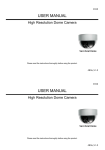
USER MANUAL
Dome Camera Series
Please read the instructions thoroughly before using the product.
AK015_V1.2
247Z
USER MANUAL
Dome Camera Series
Please read the instructions thoroughly before using the product.
AK015_V1.2
CAUTION
RISK OF ELECTRIC SHOCK
CAUTION:
To reduce the risk of electric shock, do not expose this apparatus to rain or moisture.
Only operate this apparatus from the type of power source indicated on the label.
The company shall not be liable for any damages arising out of any improper use, even if we have been advised of the
possibility of such damages.
The lightning flash with arrowhead symbol, within an equilateral triangle, is intended to alert the user to the
presence of uninsulated “dangerous voltage” within the product’s enclosure that may be of sufficient
magnitude to constitute a risk of electric shock to persons.
This exclamation point within an equilateral triangle is intended to alert the user to the presence of important
operating and maintenance (servicing) instructions in the literature accompanying the appliance.
ROHS Announcement
All lead-free products offered by the company comply with the requirements of the European law on the
Restriction of Hazardous Substances (RoHS) directive, which means our manufacture processes and
products are strictly “lead-free” and without the hazardous substances cited in the directive.
The crossed-out wheeled bin mark symbolizes that within the European Union the product must be collected
seperately at the product end-of-life. This applies to your product and any peripherals marked with this
symbol. Do not dispose of these products as unsorted municipal waste.
CE Mark
This apparatus is manufactured to comply with the radio interference.
The company does not warrant that this manual will be uninterrupted or error-free. We reserve the right to
revise or remove any content in this manual at any time.
CAUTION
RISK OF ELECTRIC SHOCK
CAUTION:
To reduce the risk of electric shock, do not expose this apparatus to rain or moisture.
Only operate this apparatus from the type of power source indicated on the label.
The company shall not be liable for any damages arising out of any improper use, even if we have been advised of the
possibility of such damages.
The lightning flash with arrowhead symbol, within an equilateral triangle, is intended to alert the user to the
presence of uninsulated “dangerous voltage” within the product’s enclosure that may be of sufficient
magnitude to constitute a risk of electric shock to persons.
This exclamation point within an equilateral triangle is intended to alert the user to the presence of important
operating and maintenance (servicing) instructions in the literature accompanying the appliance.
ROHS Announcement
All lead-free products offered by the company comply with the requirements of the European law on the
Restriction of Hazardous Substances (RoHS) directive, which means our manufacture processes and
products are strictly “lead-free” and without the hazardous substances cited in the directive.
The crossed-out wheeled bin mark symbolizes that within the European Union the product must be collected
seperately at the product end-of-life. This applies to your product and any peripherals marked with this
symbol. Do not dispose of these products as unsorted municipal waste.
CE Mark
This apparatus is manufactured to comply with the radio interference.
The company does not warrant that this manual will be uninterrupted or error-free. We reserve the right to
revise or remove any content in this manual at any time.
OVERVIEW
This camera series is designed to quickly upgrade your surveillance system without the need for
re-decoration or re-wiring. This dome camera is equipped with a vari-focal lens, and its vandal-proof
feature can withstand external force damages.
FEATURES
1.
2.
3.
4.
5.
1/3” Color CCD
F1.4 Large Aperture
f4.0 ~ f9.0mm Vari-focal Lens
Excellent low lux performance below 0.1 Lux at F1.4
Vandal-proof Housing Design (IPxx7)
PACKAGE CONTENT
Please make sure you have the following items in your sales package:
Vari-Focal Dome Camera
with Power and Video Cable * 1
User Manual * 1
OVERVIEW
This camera series is designed to quickly upgrade your surveillance system without the need for
re-decoration or re-wiring. This dome camera is equipped with a vari-focal lens, and its vandal-proof
feature can withstand external force damages.
FEATURES
1.
2.
3.
4.
5.
1/3” Color CCD
F1.4 Large Aperture
f4.0 ~ f9.0mm Vari-focal Lens
Excellent low lux performance below 0.1 Lux at F1.4
Vandal-proof Housing Design (IPxx7)
PACKAGE CONTENT
Please make sure you have the following items in your sales package:
Vari-Focal Dome Camera
with Power and Video Cable * 1
User Manual * 1
SPECIFICATIONS*
MODEL
Vari-Focal Dome Camera
Pick up Element
1/3" color CCD
Number of Pixel
512(H) x 492(V) <NTSC> / 512(H) x 582(V) <PAL>
Resolution
Min. Illumination
S/N Ratio
Electronic Shutter
Lens
Lens Angle
Standard
Below 0.1 Lux / F1.4
More than 48dB (AGC off)
1/60 (1/50) to 1/100,000 sec
f4.0mm ~ f9.0mm
75° ~ 36°
Iris Mode
AES
White Balance
ATW
Vandal-Proof Rating
IPxx7
Video Output
Power Source (±10%)
Current Consumption (±10%)
Dimension (mm)**
Net Weight (g)
1.0 Vp-p composite, 75Ω
DC12V
80mA
124.3(Ø) x 92(H)
460
* The specifications are subject to change without notice.
** Dimensional Tolerance: ± 5mm
SPECIFICATIONS*
MODEL
Vari-Focal Dome Camera
Pick up Element
1/3" color CCD
Number of Pixel
512(H) x 492(V) <NTSC> / 512(H) x 582(V) <PAL>
Resolution
Min. Illumination
S/N Ratio
Electronic Shutter
Lens
Lens Angle
Standard
Below 0.1 Lux / F1.4
More than 48dB (AGC off)
1/60 (1/50) to 1/100,000 sec
f4.0mm ~ f9.0mm
75° ~ 36°
Iris Mode
AES
White Balance
ATW
Vandal-Proof Rating
IPxx7
Video Output
Power Source (±10%)
Current Consumption (±10%)
Dimension (mm)**
Net Weight (g)
* The specifications are subject to change without notice.
** Dimensional Tolerance: ± 5mm
1.0 Vp-p composite, 75Ω
DC12V
80mA
124.3(Ø) x 92(H)
460
LENS ANGLE ADJUSTMENT
The lens can be panned left or right for angle adjustment, maximum 60° respectively from the
default position .
CONNECTION
1. DC12V Terminal
Connect the power connector of the camera to a DC 12V regulated power supply.
NOTE: Please use a regulated DC12V power adaptor to operate this unit. The power tolerance of this unit is DC12V
± 10% (DC 10.8V ~ DC 13.2V). A power input of more than the DC 13.2V will damage this unit.
2. Connect the camera video output to the input of the DVR with a 75Ω coaxial cable.
LENS ANGLE ADJUSTMENT
The lens can be panned left or right for angle adjustment, maximum 60° respectively from the
default position .
CONNECTION
1. DC12V Terminal
Connect the power connector of the camera to a DC 12V regulated power supply.
NOTE: Please use a regulated DC12V power adaptor to operate this unit. The power tolerance of this unit is DC12V
± 10% (DC 10.8V ~ DC 13.2V). A power input of more than the DC 13.2V will damage this unit.
2. Connect the camera video output to the input of the DVR with a 75Ω coaxial cable
INSTALLATION
Step1 Remove the Dome Cover
Step2 Remove the Black Shield Case
Remove the Dome Cover by turning it
First, unscrew the Black Shield Case. Then remove
counterclockwise to the end and then take it off.
it by pressing the two sides and then pulling it
outward.
INSTALLATION
Step1 Remove the Dome Cover
Step2 Remove the Black Shield Case
Remove the Dome Cover by turning it
First, unscrew the Black Shield Case. Then remove
counterclockwise to the end and then take it off.
it by pressing the two sides and then pulling it
outward.
Step3 Align the screw holes
To install the camera; firstly, aim the “front view”
of the camera at your desired “securing area.”
Then swivel the black rotatable plate to let the
1st and 2nd screw holes align with those on the
camera base. So the 3rd one will align
Step4 Fasten the screws
Fasten the 3 screws to the ideal installation
position (e.g. on the ceiling or on the wall).
Then connect the power and video cable to the
power supply and the input of the DVR. (For
details, please refer to the CONNECTION section)
simultaneously.
Note:
1. Screws are not supplied with the sales package. For installation, please purchase the suitable
screws.
2. For safety, always let the power and video line concealed behind the installation position.
Step3 Align the screw holes
Step4 Fasten the screws
To install the camera; firstly, aim the “front view”
Fasten the 3 screws to the ideal installation
of the camera at your desired “securing area.”
position (e.g. on the ceiling or on the wall).
Then swivel the black rotatable plate to let the
Then connect the power and video cable to the
1st and 2nd screw holes align with those on the
power supply and the input of the DVR. (For
camera base. So the 3rd one will align
details, please refer to the CONNECTION section)
simultaneously.
Note:
Step1 Screws are not supplied with the sales package. For installation, please purchase the suitable
screws.
Step2 For safety, always let the power and video line concealed behind the installation position.
Step5 Adjust the angle of the camera
To adjust the angle of the camera, swivel the
black rotatable plate from the center to the left or
to the right, maximum 60° (Pan).
Adjust the tilt angle by moving the lens,
maximum 90°. (Tilt)
Use a flat-headed screwdriver to loosen the
pivots on the lens. First adjust the 1st pivot to
zoom-in and zoom-out (Zoom). Second, adjust
the 2nd pivot to fine tune the focal lens.
Secure these two pivots after the adjustment is
completed.
Finally fasten the screw on the side of lens to
fix the tilt angle after the optimized
positioning is achieved.
Note: When adjusting the title angle, please do not tilt the camera lens to be more than 90°.
Step5 Adjust the angle of the camera
To adjust the angle of the camera, swivel the
black rotatable plate from the center to the left or
to the right, maximum 60° (Pan).
Adjust the tilt angle by moving the lens,
maximum 90°. (Tilt)
Use a flat-headed screwdriver to loosen the
pivots on the lens. First adjust the 1st pivot to
zoom-in and zoom-out (Zoom). Second, adjust
the 2nd pivot to fine tune the focal lens.
Secure these two pivots after the adjustment is
completed.
Finally fasten the screw on the side of lens to
fix the tilt angle after the optimized
positioning is achieved.
Note: When adjusting the title angle, please do not tilt the camera lens to be more than 90°.
Step6 Replace the Black Shield Case
Step7 Replace the Dome Cover
Replace the Black Shield Case to the camera base.
Replace the dome cover to camera base and turn it
Ensure that the Black Shield Case does not cover the
clockwise to the end to secure it.
lens.
NOTE: No need to screw the Black Shield Case.
Step6 Replace the Black Shield Case
Step7 Replace the Dome Cover
Replace the Black Shield Case to the camera
Replace the dome cover to camera base and turn it
base. Ensure that the Black Shield Case does not
clockwise to the end to secure it.
cover the lens.
NOTE: No need to screw the Black Shield Case.
248Z
USER MANUAL
High Resolution Dome Camera
Please read the instructions thoroughly before using the product.
AK016_V1.1
248Z
USER MANUAL
High Resolution Dome Camera
Please read the instructions thoroughly before using the product.
AK016_V1.1
CAUTION
RISK OF ELECTRIC SHOCK
CAUTION:
To reduce the risk of electric shock, do not expose this apparatus to rain or moisture.
Only operate this apparatus from the type of power source indicated on the label.
The company shall not be liable for any damages arising out of any improper use, even if we have been advised of the
possibility of such damages.
The lightning flash with arrowhead symbol, within an equilateral triangle, is intended to alert the user to the
presence of uninsulated “dangerous voltage” within the product’s enclosure that may be of sufficient
magnitude to constitute a risk of electric shock to persons.
This exclamation point within an equilateral triangle is intended to alert the user to the presence of important
operating and maintenance (servicing) instructions in the literature accompanying the appliance.
ROHS Announcement
All lead-free products offered by the company comply with the requirements of the European law on the
Restriction of Hazardous Substances (RoHS) directive, which means our manufacture processes and
products are strictly “lead-free” and without the hazardous substances cited in the directive.
The crossed-out wheeled bin mark symbolizes that within the European Union the product must be collected
seperately at the product end-of-life. This applies to your product and any peripherals marked with this
symbol. Do not dispose of these products as unsorted municipal waste.
CE Mark
This apparatus is manufactured to comply with the radio interference.
The company does not warrant that this manual will be uninterrupted or error-free. We reserve the right to
revise or remove any content in this manual at any time.
CAUTION
RISK OF ELECTRIC SHOCK
CAUTION:
To reduce the risk of electric shock, do not expose this apparatus to rain or moisture.
Only operate this apparatus from the type of power source indicated on the label.
The company shall not be liable for any damages arising out of any improper use, even if we have been advised of the
possibility of such damages.
The lightning flash with arrowhead symbol, within an equilateral triangle, is intended to alert the user to the
presence of uninsulated “dangerous voltage” within the product’s enclosure that may be of sufficient
magnitude to constitute a risk of electric shock to persons.
This exclamation point within an equilateral triangle is intended to alert the user to the presence of important
operating and maintenance (servicing) instructions in the literature accompanying the appliance.
ROHS Announcement
All lead-free products offered by the company comply with the requirements of the European law on the
Restriction of Hazardous Substances (RoHS) directive, which means our manufacture processes and
products are strictly “lead-free” and without the hazardous substances cited in the directive.
The crossed-out wheeled bin mark symbolizes that within the European Union the product must be collected
seperately at the product end-of-life. This applies to your product and any peripherals marked with this
symbol. Do not dispose of these products as unsorted municipal waste.
CE Mark
This apparatus is manufactured to comply with the radio interference.
The company does not warrant that this manual will be uninterrupted or error-free. We reserve the right to
revise or remove any content in this manual at any time.
OVERVIEW
This camera series is designed to quickly upgrade your surveillance system without the need for
re-decoration or re-wiring. This high-resolution camera is equipped with a vari-focal lens (Auto Iris), and
its vandal-proof feature can withstand external force damages.
FEATURES
1.
2.
3.
4.
5.
1/3” HR Color CCD
F1.4 Large Aperture
f4.0 ~ f9.0mm Vari-focal Lens (Auto Iris)
Supports 0.15 Lux at F1.4
Vandal-proof Housing Design (IPxx7)
PACKAGE CONTENT
Please make sure you have the following items in your sales package:
Vari-Focal Dome Camera
with Power and Video Cable * 1
User Manual * 1
OVERVIEW
This camera series is designed to quickly upgrade your surveillance system without the need for
re-decoration or re-wiring. This high-resolution camera is equipped with a vari-focal lens (Auto Iris), and
its vandal-proof feature can withstand external force damages.
FEATURES
1.
2.
3.
4.
5.
1/3” HR Color CCD
F1.4 Large Aperture
f4.0 ~ f9.0mm Vari-focal Lens (Auto Iris)
Supports 0.15 Lux at F1.4
Vandal-proof Housing Design (IPxx7)
PACKAGE CONTENT
Please make sure you have the following items in your sales package:
Vari-Focal Dome Camera
with Power and Video Cable * 1
User Manual * 1
SPECIFICATIONS*
MODEL
High Resolution Vari-Focal Dome Camera
Pick up Element
1/3" HR color CCD
Number of Pixel
771(H) x 492(V) <NTSC> / 753(H) x 582(V) <PAL>
Resolution
520 TVL
Min. Illumination
0.15 Lux / F1.4
S/N Ratio
More than 48dB (AGC off)
Electronic Shutter
1/60 (1/50) to 1/100,000 sec
Vari-focal Auto Iris Lens
f4.0mm ~ f9.0mm
Lens Angle
75° ~ 36°
IRIS Mode
Auto
White Balance
ATW
IP Rating
IPxx7
Video Output
1.0 Vp-p composite, 75Ω
Power Source (±10%)
DC12V
Current Consumption
85mA
Dimension (mm)**
124.3(Ø) x 92(H)
Net Weight (g)
460
* The specifications are subject to change without notice.
** Dimensional Tolerance: ± 5mm
SPECIFICATIONS*
MODEL
High Resolution Vari-Focal Dome Camera
Pick up Element
1/3" HR color CCD
Number of Pixel
771(H) x 492(V) <NTSC> / 753(H) x 582(V) <PAL>
Resolution
Min. Illumination
S/N Ratio
Electronic Shutter
Vari-focal Auto Iris Lens
520 TVL
0.15 Lux / F1.4
More than 48dB (AGC off)
1/60 (1/50) to 1/100,000 sec
f4.0mm ~ f9.0mm
Lens Angle
75° ~ 36°
IRIS Mode
Auto
White Balance
ATW
IP Rating
IPxx7
Video Output
1.0 Vp-p composite, 75Ω
Power Source (±10%)
DC12V
Current Consumption
85mA
Dimension (mm)**
Net Weight (g)
* The specifications are subject to change without notice.
** Dimensional Tolerance: ± 5mm
124.3(Ø) x 92(H)
460
LENS ANGLE ADJUSTMENT
The lens can be panned left or right for angle adjustment, maximum 60° respectively from the
default position .
CONNECTION
1. DC12V Terminal
Connect the power connector of the camera to a DC 12V regulated power supply.
NOTE: Please use a regulated DC12V power adaptor to operate this unit. The power tolerance of this unit is DC12V
± 10% (DC 10.8V ~ DC 13.2V). A power input of more than the DC 13.2V will damage this unit.
2. Connect the camera video output to the input of the DVR with a 75Ω coaxial cable.
LENS ANGLE ADJUSTMENT
The lens can be panned left or right for angle adjustment, maximum 60° respectively from the
default position .
CONNECTION
1. DC12V Terminal
Connect the power connector of the camera to a DC 12V regulated power supply.
NOTE: Please use a regulated DC12V power adaptor to operate this unit. The power tolerance of this unit is DC12V
± 10% (DC 10.8V ~ DC 13.2V). A power input of more than the DC 13.2V will damage this unit.
2. Connect the camera video output to the input of the DVR with a 75Ω coaxial cable.
INSTALLATION
Step1 Remove the Dome Cover
Step2 Remove the Black Shield Case
Remove the Dome Cover by turning it
First, unscrew the Black Shield Case. Then remove
counterclockwise to the end and then take it off.
it by pressing the two sides and then pulling it
outward.
INSTALLATION
Step1 Remove the Dome Cover
Step2 Remove the Black Shield Case
Remove the Dome Cover by turning it
First, unscrew the Black Shield Case. Then remove
counterclockwise to the end and then take it off.
it by pressing the two sides and then pulling it
outward.
Step3 Align the screw holes
To install the camera; firstly, aim the “front view”
of the camera at your desired “securing area.”
Then swivel the black rotatable plate to let the
1st and 2nd screw holes align with those on the
camera base. So the 3rd one will align
simultaneously.
Step4 Secure the screws
Fasten the 3 screws to the ideal installation
position (e.g. on the ceiling or on the wall).
Then connect the power and video cable to the
power supply and the input of the DVR for later
adjustments. (For the details of the connection,
please refer to the CONNECTION section).
Note:
1. Screws are not supplied with the sales package. For installation, please purchase the suitable
screws.
2. For safety, always let the power and video line concealed behind the installation position.
Step3 Align the screw holes
Step4 Secure the screws
To install the camera; firstly, aim the “front view”
Fasten the 3 screws to the ideal installation
of the camera at your desired “securing area.”
position (e.g. on the ceiling or on the wall).
Then swivel the black rotatable plate to let the
Then connect the power and video cable to the
1st and 2nd screw holes align with those on the
power supply and the input of the DVR for later
camera base. So the 3rd one will align
adjustments. (For the details of the connection,
simultaneously.
please refer to the CONNECTION section)
Note:
1. Screws are not supplied with the sales package. For installation, please purchase the suitable
screws.
2. For safety, always let the power and video line concealed behind the installation position.
Step5 Adjust the angle of the camera
To adjust the angle of the camera, swivel the
black rotatable plate from the center to the left or
to the right, maximum 60° (Pan).
Adjust the tilt angle by moving the lens,
maximum 90°. (Tilt)
Use a flat-headed screwdriver to loosen the
pivots on the lens. First adjust the 1st pivot to
zoom-in and zoom-out (Zoom). Second, adjust
the 2nd pivot to fine tune the focal lens.
Secure these two pivots after the adjustment is
completed.
Finally fasten the screw on the side of lens to fix
the tilt angle after the optimized positioning is
achieved.
Note: When adjusting the title angle, please do not tilt the camera lens to be more than 90°.
Step5 Adjust the angle of the camera
To adjust the angle of the camera, swivel the
black rotatable plate from the center to the left or
to the right, maximum 60° (Pan).
Adjust the tilt angle by moving the lens,
maximum 90°. (Tilt)
Use a flat-headed screwdriver to loosen the
pivots on the lens. First adjust the 1st pivot to
zoom-in and zoom-out (Zoom). Second, adjust
the 2nd pivot to fine tune the focal lens.
Secure these two pivots after the adjustment is
completed.
Finally fasten the screw on the side of lens to fix
the tilt angle after the optimized positioning is
achieved.
Note: When adjusting the title angle, please do not tilt the camera lens to be more than 90°.
Step6 Adjust the blue “Light Lever Tuner”
Step7 Replace the Black Shield Case
When the video output is too bright or too dark,
Replace the Black Shield Case to the camera base.
adjust the “Light Level Tuner” to get the suitable
Ensure that the Black Shield Case does not cover
light level.
the lens.
Finally secure the screw on the side of lens to
stabilize the tilt angle after the optimized
positioning is achieved.
NOTE: No need to screw the Black Shield Case.
Step6 Adjust the blue “Light Lever Tuner”..
Step7 Replace the Black Shield Case
When the video output is too bright or too dark,
Replace the Black Shield Case to the camera base.
adjust the “Light Level Tuner” to get the suitable
Ensure that the Black Shield Case does not cover
light level.
the lens.
Finally secure the screw on the side of lens to
stabilize the tilt angle after the optimized
positioning is achieved.
NOTE: No need to screw the Black Shield Case.
Step8 Replace the Dome Cover
Replace the dome cover to the camera base and
turn it clockwise to the end to secure it.
Step8 Replace the Dome Cover
Replace the dome cover to the camera base and
turn it clockwise to the end to secure it.