1
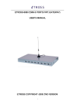
Aristel
AN4004
GSM FIXED WIRELESS
TERMINAL
MANUAL
V3.1
This manual contains important information.
Please read before using the equipment.
Contents
3
Function Description:.................................................................4
4
Operation Guide:.......................................................................4
4.1
Power On.............................................................................4
4.2
Panel indicator LED status ...................................................5
4.3
Make a call ..........................................................................5
4.4
Receive a call.......................................................................5
4.6
Parameter setting..................................................................5
4.6.1 Command table: .............................................................6
4.6.2 Factory default setting: ...................................................6
5
Configuration and installation ....................................................8
6
Technical data............................................................................9
1 Introduction
Congratulations on choosing an Aristel GSM Fixed Wireless Terminal.
Your Aristel Fixed Wireless Terminal ( FWT ) is designed to work on GSM
networks . It can be connected to single line telephones ( SLT ) or PABX systems
using analogue SLT ports. It is supplied with rack mounting brackets.
2 Warning
Please observe the following:
1. Avoid using this product in petrol stations, bunkers and places of chemical storage.
2. Avoid using this device in areas where wireless transmission equipment is
restricted (such as hospitals, health care facilities and on board aircraft).
3. Use only 2 wire line cords ( supplied ) when connecting to SLTs and PABX
systems.
4. The
voice quality may vary between networks.
5. As of March 2009, the following networks will work with this device
Telstra GSM 900/1800, Optus 900/1800, Vodafone 900/1800
Telstra Next G SIM cards will default to GSM 900/1800 Telstra network. Installers should
check GSM site reception using a GSM handset or a 3G handset set to GSM only. This is
important for country areas. Hutchison ‘3’ will not work with this FWT. It is a 3g only network.
6. The equipment should be installed and maintained by a qualified personal.
7. Position the antennae in a location where signal strength is not impaired.
3 Function Description
This FWT has the following:
1. Standard RJ11 phone socket interface.
2. Caller ID with DTMF.
3. This FWT has the flexibility to bar call destinations such as 1900 calls, national
long distance calls, international calls, mobile calls or local phone calls.
4. Supports locking SIM card, locking network, locking district functions.
5. Supports traditional PBX access and reversal on idle.
6. Dialing control (Ability to set up several special phone numbers, restricted
numbers).
7. Real time displaying of wireless network signal strength.
4 Operation Guide
4.1 Power On
Turn on the power switch. The equipment will initialize itself and search the
network. This will take about 20 seconds. During this process, the running
indicator LED keeps flashing. After this process is finished, the equipment is
ready, and the signal indicator LED will be lit. Dial tone can be heard if off- hook.
If the equipment is locked (or SIM locked or network locked), the equipment
checks itself. And if the check inspection has failed, the equipment will send out
error tone for 2 minutes and release the connection.
4.2 Panel indicator LED status
(Count from the left to the right.)
1st LED – Off- hook LED:
Off-hook LED is on after pick up handset or press “Handfree” key.
nd
2 LED – Speaking LED:
Speaking LED is on when the conversation start.
rd th th
3 ,4 ,5 LED – Signal LED :
Indicate the strength of the signal.
th
6 LED – Power Indicator LED:
Power Indicator LED is on when switch on the power.
4.3 Make a call
When the signal LEDs are on, and you hear dial tone after you pick up the
handset or connect to the PBX trunk, then you can make a call.
4.4 Receive a call
On an incoming call, ring current is sent to the SLT or PBX device with
Australian ring cadence.
4.5 Parameter setting
The parameters can be set by a telephone keypad. Enter the setting mode
by command “**##**7788#’, exit from the setting mode by command
“**##7788#”. One long beep can be heard if successful. Two short beeps can be
heard if unsuccessful. After completing the setting command, hang up, and then
pickup the handset to set another command.
4.5.1 Commands Table
Groups
Basic
Description
Set
Cancel
Local area code
**10*code#
**10*#
**11*IP1#
**11* #
**12*IP2#
**12* #
**13*IP3#
**13* #
**20*1#
**21*1#
**21*0#
**22*0#
**22*1#
**23*0#
**23*1#
**24*0#
**24*1#
**30*x#
**31*x#
**32*x#
**33*x#
**40*1#
**41*1#
**42*1#
**43*1#
**50*1#
**66*1#
**25*0#
1-4)
1-4)
1-4)
1-4)
**40*#
**41*#
**43*0#
**44*0#
**50*0#
**66*0#
National long
IP1
International
distance IP2
distance
long
Nonlocal Mobile IP3
Local calls barred
Incoming barred
National long distance
Call
Restriction barred
International
long
distance barred
Local Mobile barred
Speaker Gain
Volume
Microphone Gain
Adjusting Speaker Volume
Microphone Volume
Card Random PIN Lock
Lock
lock Fix PIN lock
Manage
Machine lock
Network lock
Billing Meter
Hide local phone number
Other
Commands Clear “0” for Nonlocal
Mobile
Reset to Default value
**51*1#
(x:
(x:
(x:
(x:
**51*0#
**52*#
Any programming will come into effect only after power reset.
4.5.2 Default setting of the factory
Special code: 6000
Local area code: none
IP1: none
Mobile IP: off
Barr Incoming: off
Barr national long distance: off
Barr national long distance: off
Barr local call: off
Barr local handset: off
PIN: 1234
Speaker Gain: 3
Speaker volume: 3
Microphone gain: 3
Microphone volume: 3
Card lock: off
Machine lock: off
5 Configuration and installation
1) Packing List:
l Main unit
l Antennae
l User Manual
l Power cable
1 set
4 pieces
1 volume
1 piece
2). Installation Steps:
The equipment uses the GSM network(s) and requires an active SIM card(s)
which are NOT pin locked.
? Install the Fixed Wireless Terminal in a suitable place.
? Turn off the main power switch at the back of the unit.
? Install an active SIM card.
a) Take off the 8 screws of the SIM card cover underneath the unit.
b) Open the SIM card cover. Move the SIM card clamp according to the
arrow.
c) Lift the SIM card clamp to insert the SIM card contact side down.
d) Close the SIM card clamp and secure it.
Close the SIM card cover
plate and replace the 8 screws.
?
Connect the antenna(e) into the socket(s).
?
using the 2 wire line cord(s) provided, connect the SLT or the PBX SLT
port to the FWT RJ11 socket..
? Connected the power cord..
? Turn on the main power switch and the relevant individual power switches
at the back of the FWT. The unit will be operational after the initialization
period of up to 30 seconds..
6 Technical Data
1)
2)
3)
4)
5)
Antenna interface standard: GSM900/1800 MHz or GSM
850/900/1800/1900 MHz or as stated on the equipment case.
SIM card: Support 3V/1.8 V (adaptive) G-SIM card
Phone interface: DTMF line interface (RJ-11 phone interface)
On-hook voltage: 45V
Off-hook current: 30 mA/41mA
Dialing tone frequency: 450 Hz
Antenna interface: antenna gain > 3.5 DB
Sensitivity < -104 DBM
Antenna transmission power: < 3 W
Impedance: 50 ohm
Working environment:
Operation temperature: -20 ? ~ 60 ?
Operation humidity: 45% ~ 95%
Storage temperature: -20 ? ~ 60 ?
Atmosphere pressure: 86 ~ 106 Kpa
Environment noise: < 60dB
This device has a 12 months warranty from the date of purchase.