1
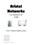
DECT Wireless Door Station - AN WDS
The wireless door phone - AN WDS is designed to work on the AN105 DECT system along with
the other DECT handsets. Being wireless has its own advantages such as simple installation,
good reception, low maintenance, mobility etc. Other features include door latch release, auxiliary
device connection, external call button, call indicator lamp and egress door open.
Door phone installation
The Door phone can be either flush mounted as it is or surface mounted using the stainless steel
surface mount box - AN SMB. Position the door phone upright so that the speaker is on the left
hand side and the microphone is on the right hand side.
Connect a 12Vdc/ 1A power supply between Alt + and Alt – terminals on the green connection
block, making sure the polarity is correctly maintained. Position the whip antenna so that the
radiating element does not touch any object but is simply positioned vertically up or down in a
free space outside the steel box. Locate the base in such a way that it does not exceed 40m
from the door phone and lies in a line of sight, avoiding obstructions as much as possible
When the door phone is powered up, the Green LED in the door phone may flash slowly,
indicating that the door phone is in search mode.
Door phone registration
1. Power up the base and register the first handset as HS1 in the usual manner
2. Before registration check the existing registered devices by the following method:
Using HS1 operate Up/Down arrow key to select BS Setting, then press INT
MASTER PIN = 0000, then press INT
By the up/down arrow key select Remove HS
Remove HS? M----- should appear. (If any other handsets are registered M234----- etc
may appear. In that case handsets 2, 3 and 4 should be removed by entering the
corresponding HS number )
Press the Green Handset button to end programming
3. Using the HS1 register the Door phone as HS2
4. To register the Door phone select BS Setting using HS1
5. MASTER PIN = 0000
6. Select New HS
7. Sub PIN = 0000 and INT ( The RED LED at the base will start flashing )
8. Press the RED Button on the door phone mother board
9. The RED LED on the door phone will start to flash quickly for some time and then flash
slowly. This is an indication that the door phone is registered
10. Door phone registration may be confirmed as in item 2 (The display will be M2---)
11. The door phone is ready for use. End programming by pressing the green handset button.
Aristel Networks Pty Ltd
Page 1 /2
16 – 01 - 2007
Door phone wiring diagram
Door Latch installation
1. Connect a 12Vdc/1A power supply between Alt + and Alt – taking care polarity is
maintained correctly
2. Short circuit Alt + and C. See note * below
3. Connect the door latch between Alt – and NO terminals.
Note * - If power from the Door phone is not required, step 2 may be omitted.
A DCLIU may be connected between Alt- and NO which may operate a door latch in turn.
Door phone Operation
Press the door phone button to make a call
HS1 will ring. At the same time a ring tone will be heard at the door phone
HS1 answers the call by pressing the green handset button
HS1 can activate the door latch and open the door by pressing *
nd
HS1 can also activate the Auxiliary Device( 2 door for example) by pressing 5
HS1 should terminate the call at the end by pressing the green handset button.
It is also possible to call the door phone (HS2) from any other handset and activate the
door latch to open the door.
Aristel Networks Pty Ltd
Page 2 /2
16 – 01 - 2007